
Hydraulic Cylinder Limit Switches: Position Feedback and Control
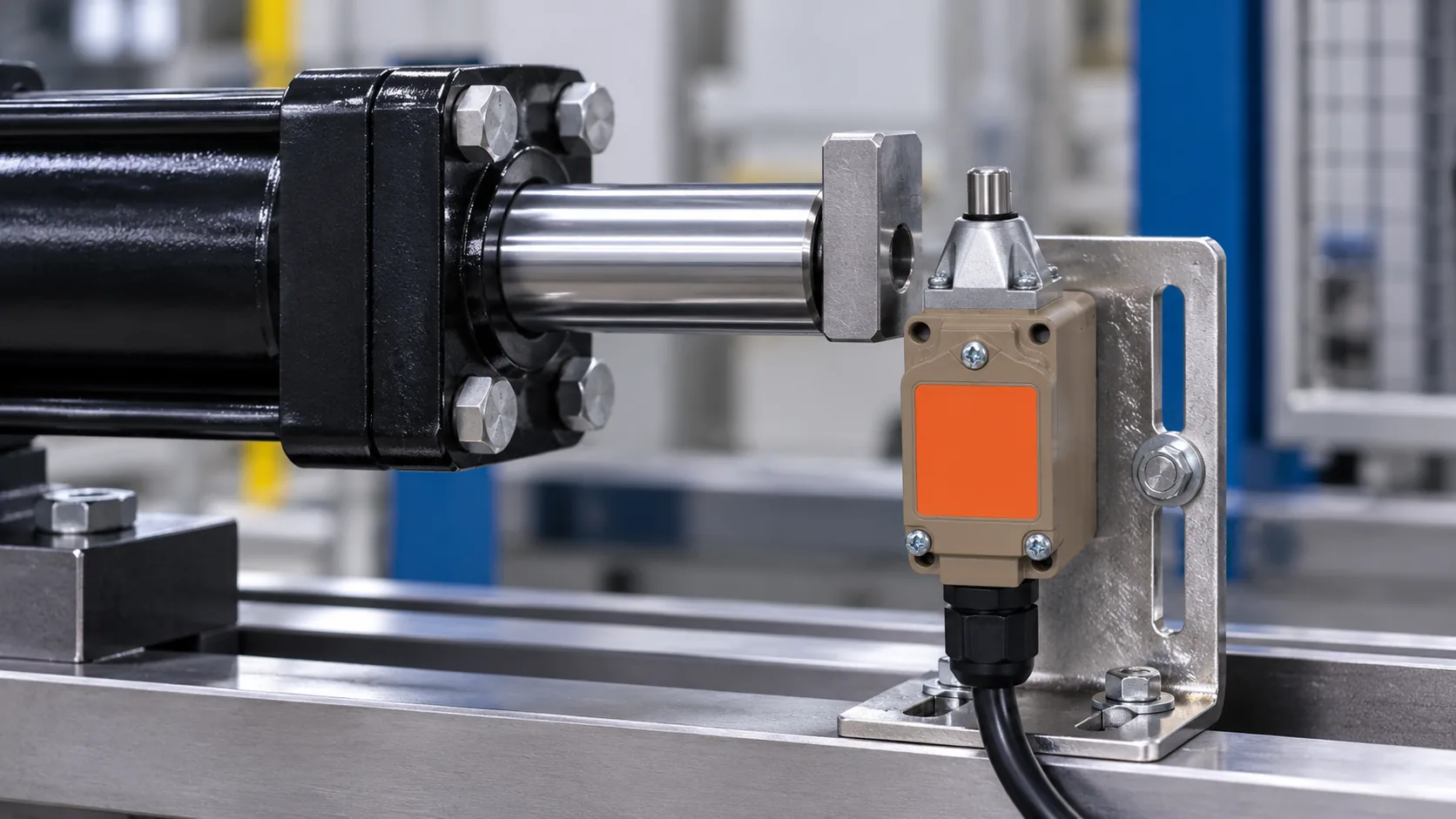
A hydraulic limit switch can report that a cylinder, slide or attached mechanism has reached a defined position. It does not measure hydraulic pressure, hold the load or make a machine safe by itself. In a typical external arrangement, a cam, target or moving fixture actuates a mechanically mounted switch; its contacts then provide a signal to a properly designed control circuit. Selection starts with the motion and target geometry, then checks actuator travel, mounting tolerance, electrical load, environment and the controller’s response. Use the hydraulic equipment manufacturer’s instructions and the machine risk assessment to define where a limit switch belongs.
Separate position sensing from hydraulic pressure sensing
A mechanical limit switch responds to physical movement. It changes contact state when a lever, plunger or other actuator is moved past its operating point. A pressure switch or pressure transducer responds to fluid pressure. The two devices answer different questions: “Where is the moving part?” versus “What pressure is present?” A cylinder can reach a mechanical stop without producing a specific pressure, and pressure can rise while the cylinder is still moving or blocked by an external load.
Use an external limit switch when the control sequence needs a discrete indication of extension, retraction or another defined position. Use a pressure-sensing device when the logic depends on pressure level. Some machines need both signals. A switch mounted near a cylinder must not be mistaken for a sensor that is in contact with hydraulic fluid or rated for line pressure.
Define the machine event before choosing a switch
Write the intended sequence in plain language. For example: when a clamp reaches its forward position, a control input permits a second motion to begin. Then identify the physical target that will actuate the switch, the mounting bracket, the permitted adjustment, and what the machine should do if the signal is missing or arrives out of order.
A limit switch is only one component in this chain. A PLC, relay or valve controller may interpret the signal, while a solenoid valve directs hydraulic flow. The switch contacts must suit the control circuit, not automatically the motor or the hydraulic valve’s power load. The applicable electrical and hydraulic design standards, the control narrative and the machine builder’s validation procedure govern the actual arrangement.
Match actuator style to the target motion
Choose the actuator according to how the target approaches and passes the switch. A top plunger responds to direct movement along its intended axis. A roller lever can be easier to actuate with a passing cam, while a rod or flexible actuator may respond to motion from a different direction. Do not select by actuator name alone. The switch must operate within the target’s travel window and must not be struck beyond its permitted mechanical movement.
Measure the full tolerance stack: cylinder stop position, bracket location, target dimensions, machine deflection and temperature-related movement. Confirm pretravel, operating position, overtravel and release point for the exact switch. If a production machine reaches different positions under load, test the feedback point at the real operating conditions instead of assuming the cylinder rod always stops at a nominal dimension.
| Verificación de diseño | Pregunta para responder | Verification evidence |
|---|---|---|
| Target path | Does the cam or moving fixture contact the actuator in the intended direction? | Assembly drawing and slow-cycle prototype observation |
| Operating window | Does the switch change state before the mechanical stop without excessive actuator travel? | Exact switch travel data and measured position tolerance |
| Lógica de control | What happens if the signal is absent, delayed or contradictory? | Approved sequence chart, fault response and controller test |
| Servicio eléctrico | What voltage, current, load type and switching frequency reach the contacts? | Model-specific ratings and circuit review |
| Service environment | Will dust, oil mist, vibration, impact or washdown reach the switch? | Exposure description and the exact enclosure specification |
Design the bracket and target as part of the sensing system
Mount the switch on a rigid surface that will not rotate or flex during operation. The target must be repeatable, and the bracket must allow the adjustment needed to set the switching point without placing a side load on a plunger designed for direct operation. Consider impact force, vibration, loose fasteners, cable routing and possible collision during maintenance or setup.
Where a cam passes the actuator, its approach profile should actuate and release the switch predictably. A sharp edge may hit the actuator hard and shorten mechanical life. A long dwell may hold the actuator at its limit. Provide a physical stop that protects the switch from absorbing cylinder force. The cylinder end stop and switch are not interchangeable mechanical stops.
Check contacts, load and controller interface
Use the exact wiring diagram to select normally open or normally closed contacts for the approved control logic. Confirm whether the circuit feeds a PLC input, relay coil or another load. The device’s AC and DC ratings may differ, and an inductive coil can stress contacts differently from a resistive load. A general current number is not enough; review voltage, load category, inrush, switching rate and the expected number of electrical operations.
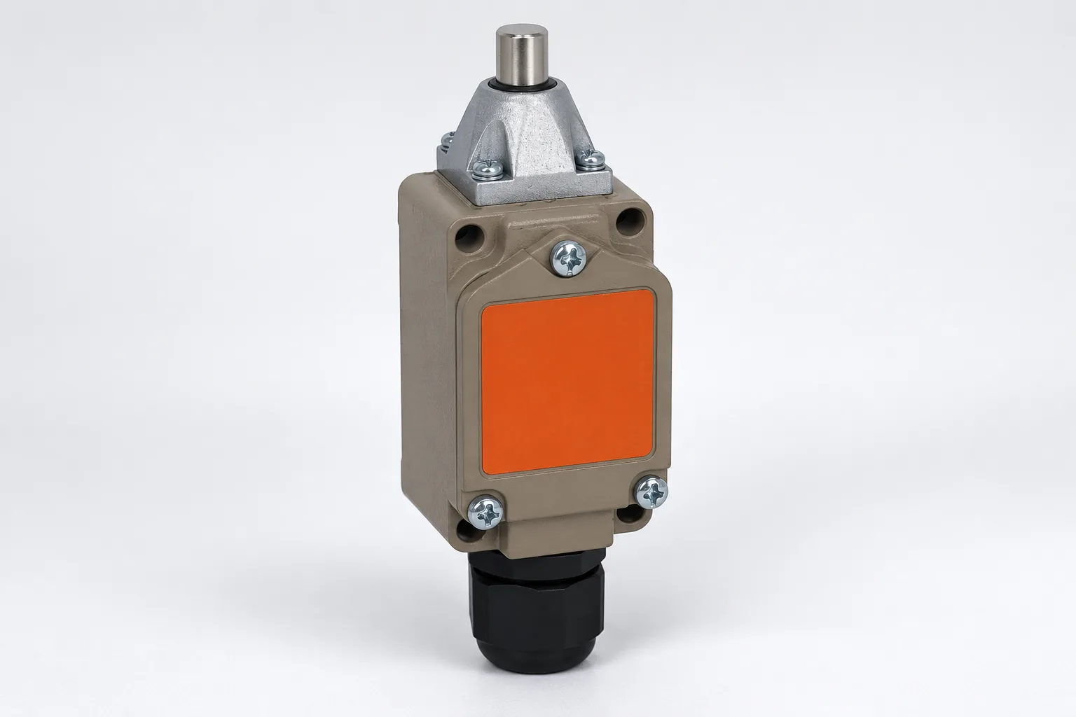
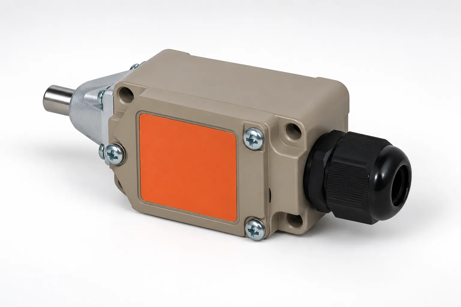
La LEMA WL-D11 top-plunger limit switch is one product example with a metal housing and a two-circuit contact arrangement listed on its product page. That page describes machine-tool, injection-molding and other machine applications; it does not specifically approve the model for hydraulic cylinders or safety functions. Confirm the current drawing, terminal form and permitted electrical duty for the order code before using it in a design. For more on selecting the actuator itself, see LEMA’s guía del actuador del interruptor de límite y mounting and repeatability guide.
Account for oil, dust, vibration and cable exposure
Hydraulic equipment can expose electrical components to oil mist, dust, washdown, vibration and impact. Record the actual exposure, including cleaning method, temperature, mounting orientation and cable movement. A general “waterproof” statement does not prove chemical compatibility or confirm a particular IP level. Verify the exact enclosure rating and the installation conditions required to preserve it.
Protect the cable from abrasion, repeated flexing, pinch points and sharp edges. Route it separately from moving rods and hot components. Use the specified gland or connector, and confirm strain relief and grounding requirements. If the application needs a sealed connector, verify the complete assembly, not just the switch body.
Validate the whole control sequence
Check the switch state at each intended position, then test the controller response and the valve sequence at reduced risk and under the machine builder’s approved commissioning procedure. Include sensor bounce, interrupted cable, open or shorted input, target looseness and restart after loss of power in the review. A PLC input filter may help with signal noise, but it cannot correct a poor mounting geometry or a switch that is being mechanically overloaded.
Do not treat a standard limit switch as a safety-rated guard interlock or protective device unless the exact component and complete safety circuit are designed and validated for that role. During setup, adjustment or maintenance, isolate electrical, hydraulic and other stored energy according to the applicable procedure. ISO 4413 addresses safety requirements for hydraulic fluid-power systems and components. IEC 60947-5-1 covers electromechanical control-circuit devices, including position switches. OSHA’s lockout/tagout rule describes control of hazardous energy in covered workplaces. The exact applicable rules depend on the machine, location and work activity.
Prepare an RFQ for a hydraulic position-feedback switch
- Provide the cylinder drawing, stroke, target geometry and the positions to detect.
- Show the bracket, actuator direction, tolerance range, mechanical stop and required adjustment.
- Specify the control voltage, AC or DC, input type, contact logic, load and switching rate.
- Describe oil, dust, washdown, temperature, vibration and cable-routing conditions.
- State whether the switch provides ordinary sequence feedback or a required safety function.
- Request the exact model drawing, actuator travel, ratings, terminal diagram and installation instructions.
- Define the sample test plan, including position repeatability, release point, fault response and cycle checks.
LEMA’s AC/DC contact-rating guide explains why a limit switch’s circuit type and load must be verified separately. If the input is intended to stop or sequence a hydraulic motion, the machine designer should approve the whole control response rather than relying on the switch’s appearance or contact count.
Watch a limit-switch cylinder sequence example
This educational hydraulic-circuit lesson demonstrates a cylinder sequence initiated by a limit switch. It is a general teaching example, not a LEMA wiring diagram or a validated safety circuit. Use the actual system schematic, component data and risk controls for a production machine.
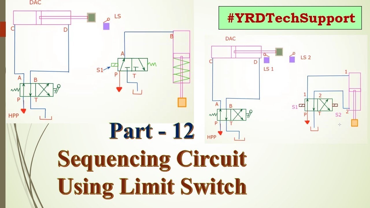
Watch the hydraulic limit-switch sequencing lesson on YouTube.
Preguntas frecuentes
Does a hydraulic limit switch measure cylinder pressure?
No. A mechanical limit switch changes state when an external target moves its actuator. Use a pressure switch or transducer when the control logic depends on fluid pressure.
Can the limit switch be mounted directly on a cylinder rod?
Only if the switch, actuator and mounting arrangement are designed for that geometry. Many installations use a separate bracket and target. Prevent side loading, impact and overtravel beyond the exact model’s limits.
Can a limit switch directly operate a hydraulic valve or pump motor?
Only if its electrical ratings and switching category cover the actual load. More commonly, a switch provides a control input to a relay, PLC or other controller that commands the machine’s power components.
Is the WL-D11 approved for every hydraulic-cylinder application?
No. LEMA lists WL-D11 as a top-plunger machine limit switch, but does not make a universal hydraulic-cylinder or safety approval claim. Confirm the exact order code, mounting, electrical duty and application acceptance with the equipment designer.