
Micro switch operating speed and switching frequency describe different limits. Operating speed concerns how quickly the mechanism moves the actuator, usually expressed as a distance per unit time at a defined point. Switching frequency concerns how often a specified operating cycle can repeat. A machine can repeat slowly yet strike the actuator too quickly, or move it gently while repeating more often than the rated duty permits. Compare both with the exact contact load, travel, return motion and test conditions before approving a switch.
El LEMA KW7 micro switch page lists operating speed separately from mechanical and electrical operating frequency. Use that distinction when preparing an OEM application review. The published family entry needs confirmation for the complete order code, and an abbreviated or unclear unit should be clarified with the supplier rather than silently corrected.
Utiliza el guía de selección de microinterruptores industriales to place these timing checks alongside the wider load, mounting and environmental requirements for the complete component selection.
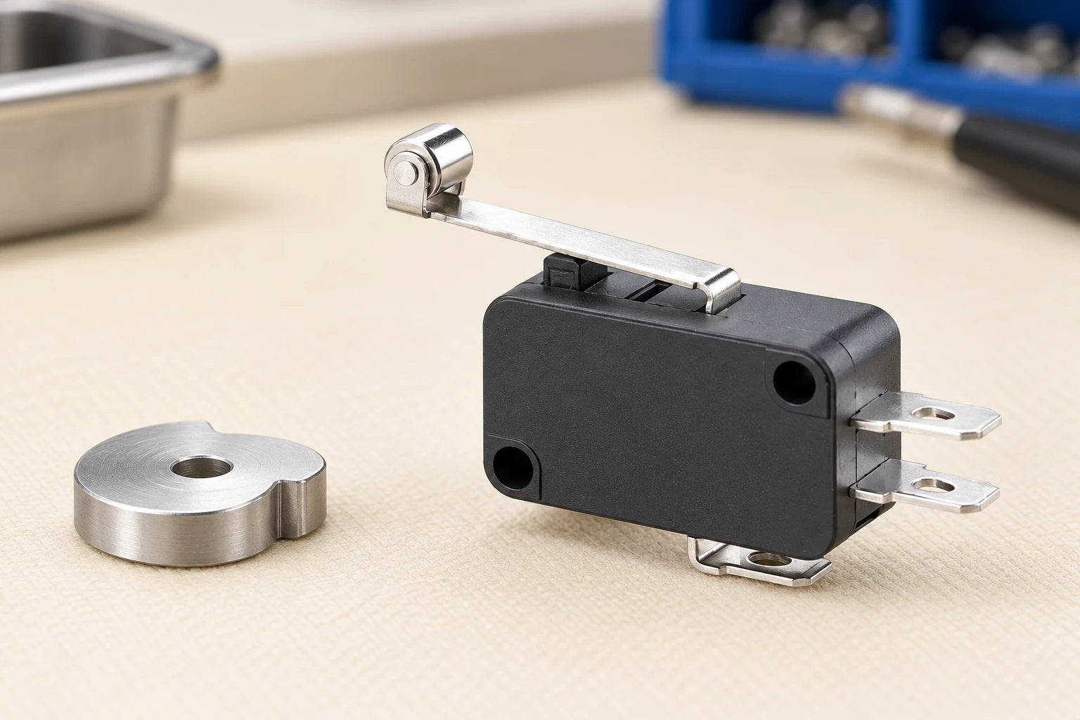
Define the movement that operating speed describes
A mechanism may contain several different speeds: the conveyor speed, cam surface speed, roller contact speed and plunger speed. These are related by geometry, but they are not always equal. Identify the point and direction specified by the component documentation. A quoted machine feed rate is insufficient if the actual target approaches the switch along a different path or through a lever.
For a plunger switch driven directly along its intended axis, the relevant motion may be straightforward to describe. A roller lever operated by a rotating cam needs more information, including the cam profile and contact point. The speed near the switching region can differ from the average motion over an entire machine stroke. Review the fastest approach and the return movement, not merely the cycle average.
Use consistent units. Metres per second, millimetres per second and operations per minute cannot be compared as though they describe the same quantity. The NIST explanation of frequency identifies a cycle per second with a hertz. That unit describes repetition; it does not describe the linear speed of a moving actuator.
Specify exactly what counts as an operating cycle
A machine cycle, an actuator depression and an electrical transition may be counted differently. One complete mechanical operation can involve actuation and release. An SPDT contact arrangement may change more than one monitored electrical path during that operation. Before converting a production rate into a switch duty, agree the counting convention used by the supplier’s frequency rating.
Also distinguish an instantaneous burst from sustained operation. A machine might run rapidly for a short period and then remain idle, or repeat continuously through an entire shift. The average rate across a shift can conceal the highest local repetition rate. Record the actual sequence, including dwell periods, rather than dividing the day’s total cycles by operating hours and assuming the result represents every condition.
| Quantity | Qué grabar | Typical comparison error |
|---|---|---|
| Actuator speed | Motion at the specified actuation point and direction | Using conveyor speed without considering cam or lever geometry |
| Frecuencia de operación | Complete operations per stated time interval and counting convention | Counting each contact transition as a separate machine cycle |
| Mechanical frequency limit | Applicable unloaded or mechanically specified test conditions | Assuming it also permits the same loaded electrical duty |
| Electrical frequency limit | Load, circuit conditions, travel and duty associated with the rating | Applying it to a different current or load type without confirmation |
| Controller recognition | Input duration, filtering, scan behavior and required response | Assuming every physical transition becomes a recorded event |
This table separates the review questions. It does not provide universal permissible speeds or frequencies for any product family.
Keep mechanical and electrical frequency ratings separate
Mechanical operation evaluates a mechanism under specified conditions, while electrical operation also involves the behavior of the switching circuit. The allowed rates can differ. Contact load, load type and switching conditions influence the electrical duty, so a mechanically acceptable repetitive motion does not by itself approve a loaded circuit at the same rate.
The KW7 page includes distinct mechanical and electrical operating-frequency entries. Ask for the associated conditions rather than taking one number out of the table. Where the product documentation identifies a contact rating code or operating-force variant, include it in the inquiry. A complete review needs the actual circuit and mechanism, not only the family name and a photograph.
The IEC catalogue describes IEC 61058-1 as the general requirements standard for appliance switches. Identify the applicable component and equipment requirements for your application, but do not treat a standard title as proof of a particular operating frequency. The relevant specification and report must establish the conditions that apply to the proposed part.
Use calculations to describe the machine, not to invent a rating
For a repeating cycle with period T seconds, frequency is f = 1/T cycles per second. If an agreed complete operation occurs 18 times per minute, its average period is 60/18, approximately 3.33 seconds, and the repetition rate is 0.30 cycles per second. These are unit conversions for an illustrative sequence, not KW7 performance limits or recommended test settings.
For a directly driven linear segment, average speed is v = distance/time. If a mechanism moves a target through an illustrative 2 millimetre segment in 0.04 second, the segment average is 50 millimetres per second. It does not reveal the peak speed or prove that the segment corresponds to the switch’s specified measurement point. A cam or lever can require a more detailed motion model.
Keep the limits of these calculations visible in the review. The full machine cycle includes approach, permitted working travel, dwell, return and clearance. An average value cannot establish that the actuator avoids impact, side loading or excessive overtravel. Use measured or validated motion information where the mechanism changes speed substantially near the switching region.
Check travel, release and the opportunity to reset
A switch needs to be operated within its defined travel conditions and allowed to return as required by the mechanism. A target that never clears the release point can prevent the intended next cycle even when the machine’s repetition rate is low. Conversely, excessive target travel can load the mechanism beyond the intended working range. Speed and frequency are only part of the mechanical acceptance.
Utiliza el micro switch travel terminology guide to distinguish pretravel, overtravel and differential travel when defining the motion. The present article addresses the time dimension of that motion. Keep the displacement drawing and timing record together so a reviewer can see where the actuator is at each stage of the cycle.
For a lever-operated variant, confirm how the supplier defines the actuation point and how the lever changes the required travel and force. Do not transfer the bare-plunger speed or force relationship to a lever tip without documentation. A mechanism can appear smooth externally while applying an unintended sideways load or failing to provide repeatable release clearance.
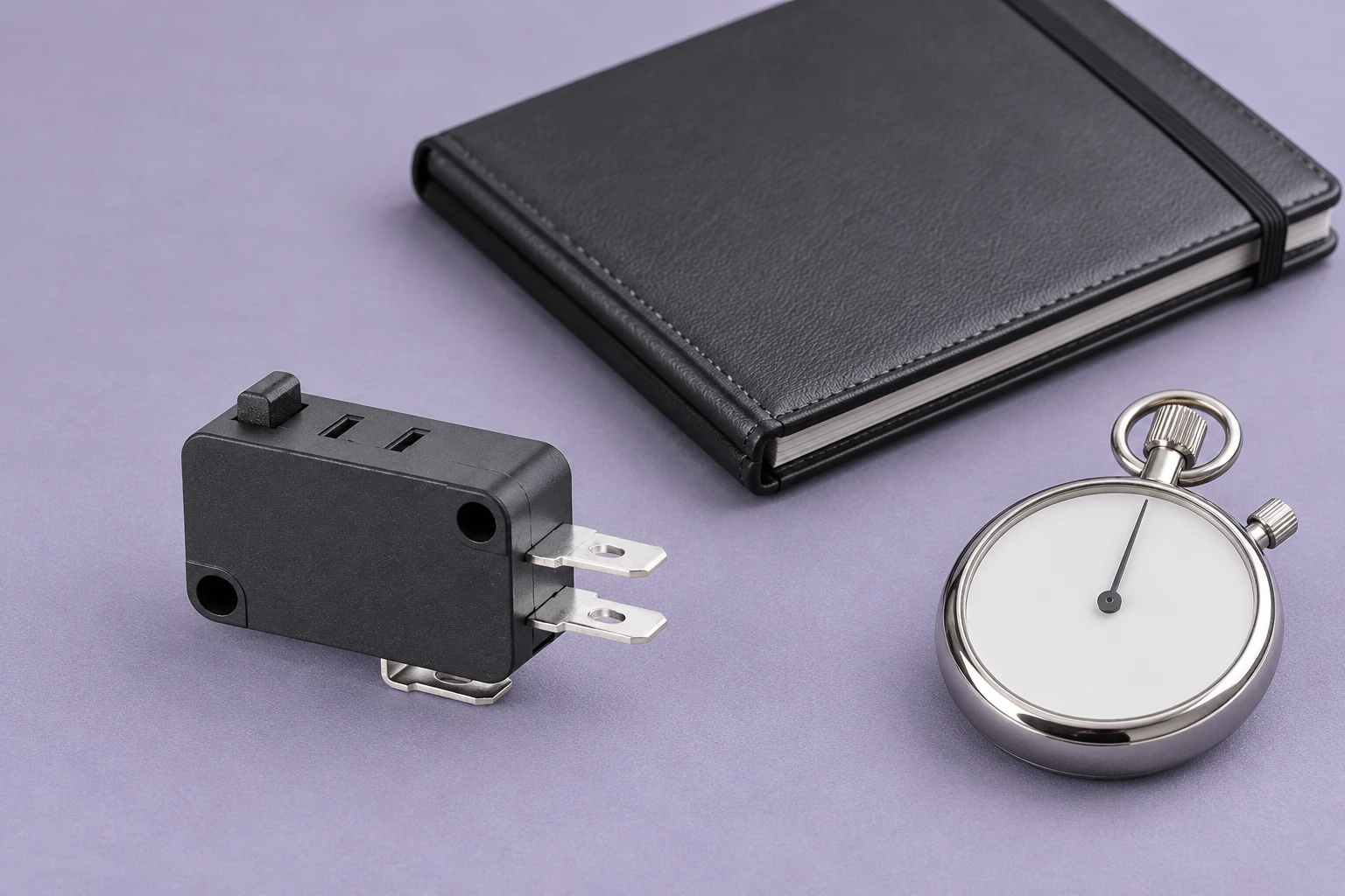
Verify that the control system recognizes the event
Physical switching and recorded machine events are different observations. A short valid contact state may be missed by a slow input scan or suppressed by an input filter. Contact bounce may also produce several transitions from one operation. Define the required stable input duration and permitted response delay with the controller and equipment documentation.
Measure the mechanical motion and electrical signal together when necessary. Identify the instrument time resolution, trigger and measurement location. A continuity beeper can establish a static path but may not show the timing needed for a fast operating sequence. The test should answer the actual acceptance question rather than simply demonstrate that the switch can click.
For the separate issue of rapid contact transitions, see micro switch contact bounce. Do not compensate for a mechanical speed or reset problem by adding arbitrary software delays. An approved filter must still allow the controller to recognize genuine events within the equipment’s required timing.
Build a representative validation sequence
Document the slowest and fastest normal motion, start-up behavior, sustained running and any short bursts. Include the actual mounting, actuator target, cable support and electrical load. A no-load hand operation is useful for an initial check, but it does not reproduce an electrically loaded production sequence. State clearly which configuration the result represents.
Laboratory or machine testing should use a defined procedure and appropriate personnel. The UK Health and Safety Executive’s electrical testing guidance discusses the control of test areas and testing risks. Use the equipment’s isolation and verification arrangements when preparing or changing the setup; this article is not a live-circuit test instruction.
Record the observed cycle timing, contact behavior, return motion and any change after the specified exposure. Keep acceptance criteria beside the results. If a supplier proposes a different actuator or force variant, review whether it changes the timing and mechanical margins established for the original configuration.
Send a useful speed and frequency inquiry
Provide the full candidate order code, mechanism sketch, direction of actuation, travel, speed profile and complete cycle sequence. Add the real electrical load and the control input requirements. Highlight unclear catalogue units and ask for a controlled specification rather than interpreting an abbreviated range yourself.
Frequency is not endurance life. The micro switch electrical versus mechanical life guide addresses total operating-life expectations under stated conditions. Keep the rate question separate from the lifetime question, then review both before approving the component for the intended duty.
Further learning: measuring periodic motion
NPTEL’s Module 14 – Lecture 1 – Vibration Measurement provides university background on measuring repeated mechanical motion. It supports the distinction between a motion record and its repetition characteristics; it does not set a micro switch speed limit or validate the illustrated LEMA product.
Watch the NPTEL measurement lecture.
Preguntas frecuentes
Are actuator speed and operating frequency the same?
No. Actuator speed describes movement per unit time at a defined point; operating frequency describes repeated operations per unit time.
Can I use the mechanical frequency limit for a loaded contact?
Not without confirmation. The electrical duty has its own applicable load and test conditions, which can differ from mechanical operation.
Does average production rate describe the fastest switch operation?
No. Short bursts, local actuator speed and return timing can differ from the average rate measured across a shift.
What should I do if a catalogue speed unit is unclear?
Request the current controlled specification for the full order code and clarify the unit, measurement point and conditions before approving the application.