
Micro switch release force is the force associated with the actuator returning through its release condition under the manufacturer’s stated measurement method. It is different from the force required to operate the switch. An assembly can push a switch successfully yet fail to release because friction, a weak return mechanism, gravity or cable drag consumes the available return margin. Review the complete force path and the measured release behavior before accepting a mechanism; do not assume that a satisfactory operating-force value proves reliable reset.
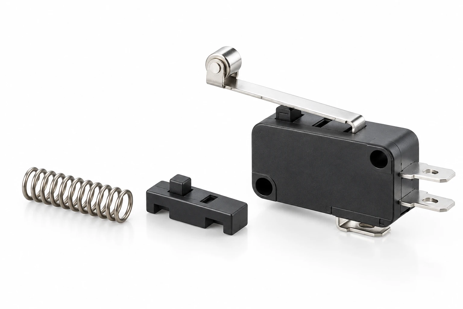
El LEMA KW7 family includes actuator and force options that must be matched to the complete order code. This guide explains an OEM return-margin review. It does not publish a universal KW7 release-force value or treat an external spring illustration as an approved design.
Distinguish operating force from release force
Operating force concerns movement into the operated condition, while release force concerns the return condition. The two values may be specified at different positions and with different limits. A drawing might use maximum, minimum or nominal values. Read the notation and the measurement location before comparing numbers.
El guía de selección de fuerza de accionamiento covers matching actuation demand to the mechanism. Release deserves its own check because the direction of motion changes and the opposing forces can change with it. Static friction, contact with a guide and the weight of a linkage may help one direction while resisting the other.
Identify the return mechanism
Draw the mechanical chain from the moving target to the switch actuator. Identify which elements drive the return: the switch’s internal mechanism, an external spring, gravity, a motor or a combination. Do not assume that an internal switch spring is intended to retract an entire machine linkage.
For each moving component, record the relevant direction and constraints. A sliding guide can bind when the mounting is misaligned. A flexible cover can press against a button. A lever can rub the housing or another part. These interactions may be absent during a loose hand test but appear after assembly or panel tightening.
Keep functions separate. A return spring may establish mechanical clearance, while the switch supplies a position signal. If the machine depends on positive return for a protective function, the complete safety design requires appropriate assessment; an ordinary release-force comparison does not establish that function.
Compare force at a common measurement point
A force applied at a long lever tip cannot be compared directly with a bare-plunger value. The geometry changes the relationship between force, displacement and moment. Obtain the manufacturer’s actuator-specific data or approved conversion rather than treating all variants as mechanically identical.
El OpenStax discussion of torque explains why the distance from a pivot matters. In a real switch assembly, the effective geometry may change during travel, and friction can add further resistance. A simple lever calculation is a starting model, not a substitute for testing the assembled mechanism.
For repeatable measurements, state the contact point, loading direction, motion rate and fixture orientation. Record whether the value is measured directly at the switch actuator or inferred through the external linkage. Do not merge results from different setups into a single acceptance number.
Build a return-force budget
List the forces that resist withdrawal throughout the return stroke. Examples include guide friction, an external seal, a flexible boot, a rubbing target and the mass of a linkage in an unfavorable orientation. Also identify the forces that assist return and whether their minimum values are documented.
Use worst-case values that have a basis in drawings, supplier data or measurements. A nominal spring force at one position may not describe the force at the release point. Likewise, a low friction reading from a clean prototype may not represent contamination, tolerance extremes or a worn guide.
When the necessary values are unknown, preserve that uncertainty. Do not assign an arbitrary percentage and call the design validated. An initial budget can show which measurement is most valuable and whether the architecture needs a stronger return arrangement or lower resistance.
Separate release position from release force
A force measurement alone does not establish that the target withdraws far enough. The mechanism must also provide the necessary movement and clearance. The micro switch travel guide distinguishes operating and release positions from other travel terms.
Record both force and displacement across approach and return. A target may relax its force while remaining in physical contact at a position that still holds the switch operated. Conversely, a mechanism may move away but snag the lever during the return path. These are different faults and need different corrections.
Consider the complete tolerance stack. The switch body, bracket, target, pivots and panel can all move relative to one another. A mechanism that resets on a nominal assembly may lose its clearance when those dimensions reach an allowed extreme. Evaluate the actual worst-case geometry and confirm it with representative assemblies.
Review orientation and external conditions
Test the intended installed orientations. Gravity may assist the return on a bench and oppose it in the finished product. A cable or flexible membrane can also move differently after the assembly is enclosed. The release check should represent the equipment configuration, not the most convenient inspection position.
Temperature, humidity, dirt and wear can alter the surrounding mechanism. Do not claim a numerical effect without evidence, but identify which interfaces could become more resistant. If exposure testing is required, use the agreed conditions and inspect the complete mechanism afterward.
The switch’s environmental rating does not automatically qualify a separate guide, boot or spring. Document those parts and their specifications as part of the assembly. A replacement accessory can change reset behavior even when the electrical switch remains the same.
Use a controlled measurement sequence
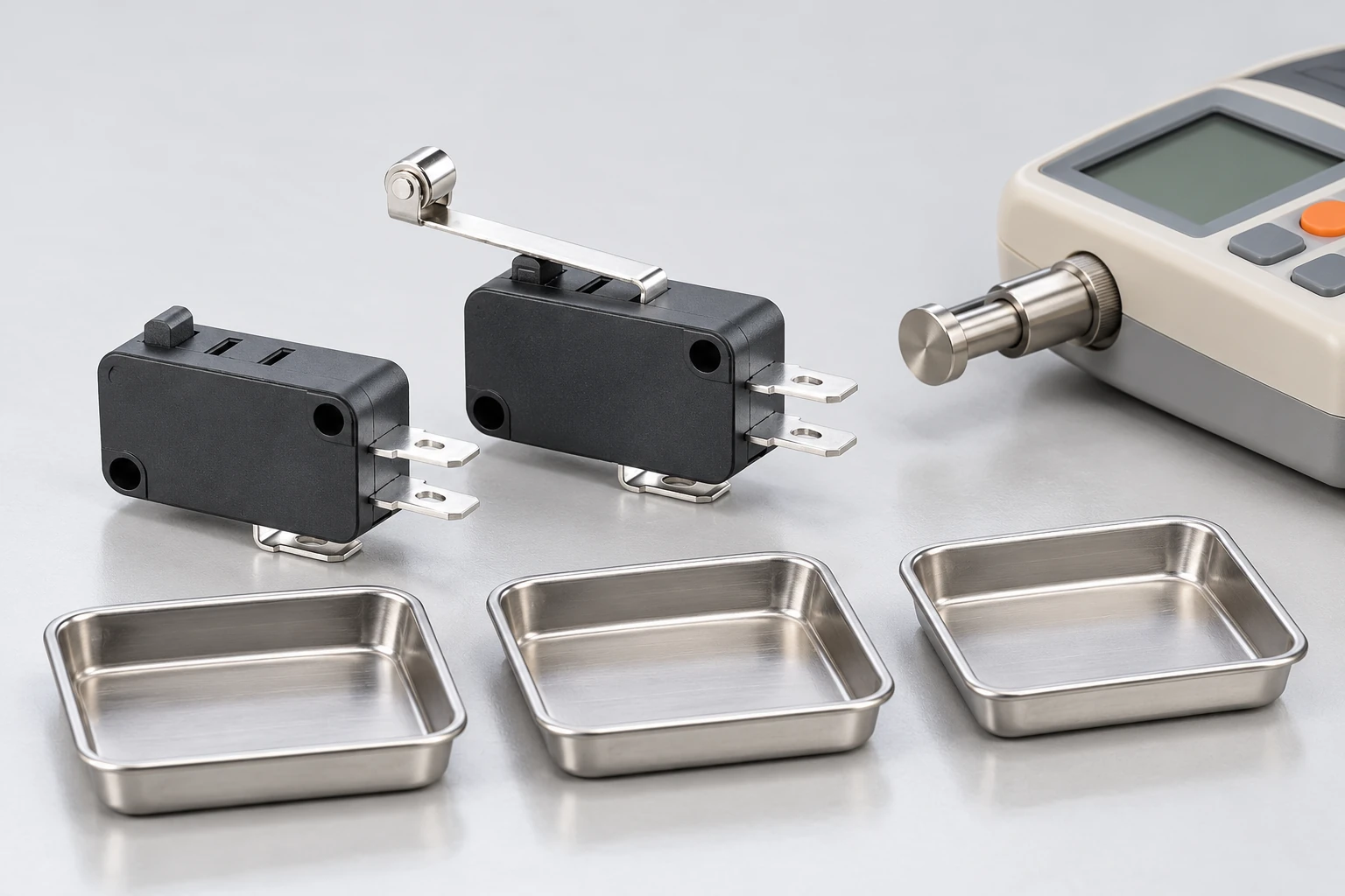
Start with an isolated, safe mechanism and confirm the exact part identity. Inspect the actuator and fixture for damage, side load or interference. Choose a force instrument with a range and resolution suitable for the expected measurement, then establish its zero and the fixture reference.
Move through a defined operating cycle and record the return transition, force and position. Repeat enough cycles to reveal variability under the agreed plan. Record individual observations rather than only an average that conceals occasional non-release. The HSE testing guidance provides safety context for the controlled electrical portion of an investigation.
Do not add a live load merely to make the test seem more realistic. The mechanical review and the electrical-duty review have different purposes. Where loaded testing is necessary, it belongs in an approved laboratory or equipment procedure with appropriate personnel and protective arrangements.
| Elemento de revisión | What must be identified | Por qué importa |
|---|---|---|
| Force value | Minimum maximum or nominal and reference point | Different limits answer different acceptance questions |
| External return | Spring gravity or driven linkage | Switch spring may not retract the mechanism |
| Resistance | Guide seal rubbing and cable effects | Return direction can have different opposing loads |
| Geometría | Lever contact point and movement path | Plunger values cannot be copied to lever tips |
| Reset evidence | Force position and electrical state together | Force alone does not prove adequate clearance |
Diagnose a failure to reset
If the contact remains operated, establish whether the actuator actually returned. A visual impression can be misleading when the final movement is small. Compare the target position, actuator position and isolated electrical state. Preserve the original adjustment until the evidence is recorded.
If the target returns but the actuator does not, investigate mechanical interference or damage. If the actuator returns and the contact state does not follow, escalate the electrical or internal-mechanism finding under the agreed failure-analysis procedure. Do not force a suspect switch back into service by bending its lever or opening its housing.
El micro switch failure-mode guide provides a broader evidence-preserving workflow. Keep the release-margin record with the failure report so a replacement does not simply reproduce the same mechanical problem.
Define acceptance and purchasing information
The purchase specification should identify the actuator variant, permitted force limits, measurement location, direction, position and test conditions. State what must happen at the equipment level: complete return, adequate clearance and the expected electrical reset within the defined sequence.
Ask for clarification when catalogue units or abbreviations are unclear. An operating-force option does not silently include a release-force guarantee for every external lever. Request the current controlled drawing and the applicable test information for the complete model.
Release approval should name the tested assembly revision and any unresolved limitations. If the mechanism, cover, spring or actuator changes, review the force budget and repeat the affected tests. Send a mechanism sketch and return observations with an OEM inquiry so the discussion concerns the actual application rather than an isolated catalogue value.
Further learning: mechanical load and deformation
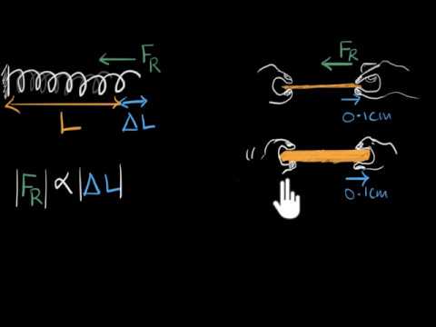
Khan Academy India – English: Stress & strain | Class 11 (India) | Physics | Khan Academy. Khan Academy explains stress and strain as mechanical background. It helps frame deformation in a loaded assembly; it does not supply a switch release-force value or a complete return-margin test method.
Watch Stress & strain | Class 11 (India) | Physics | Khan Academy.
Preguntas frecuentes
Can I calculate release force from operating force?
Do not assume a universal ratio. The values depend on the mechanism, actuator and measurement definitions. Obtain the applicable release data for the complete model and evaluate it at the same reference point as the assembly.
Should the internal switch spring return my whole linkage?
Only if the application and manufacturer evidence support that arrangement. Identify all moving parts and opposing forces. An external mechanism may require its own return provision rather than relying on an unspecified switch capability.
Why does the mechanism reset on the bench but not installed?
Orientation, clamping, cover contact, guide alignment and cable forces can change the return path. Compare the actual installed configuration with the bench setup and record displacement and electrical state through the full return.
Is a successful reset on one sample enough?
It establishes an observation for that sample and setup. The acceptance plan should address relevant tolerances, conditions and variability. Record the tested configuration and repeat the affected checks when the mechanism or actuator changes.