
A push button motor starter switch is usually an operator in the starter’s control circuit, not the device that carries motor current. In a common three-wire control arrangement, a momentary Start button energizes a starter coil and an auxiliary contact maintains the command; a Stop button interrupts the control path. The motor power contacts belong to the motor starter. Select the pushbutton by its operator, contact function, electrical duty, control voltage and required sequence, then confirm the exact product documentation and machine design.
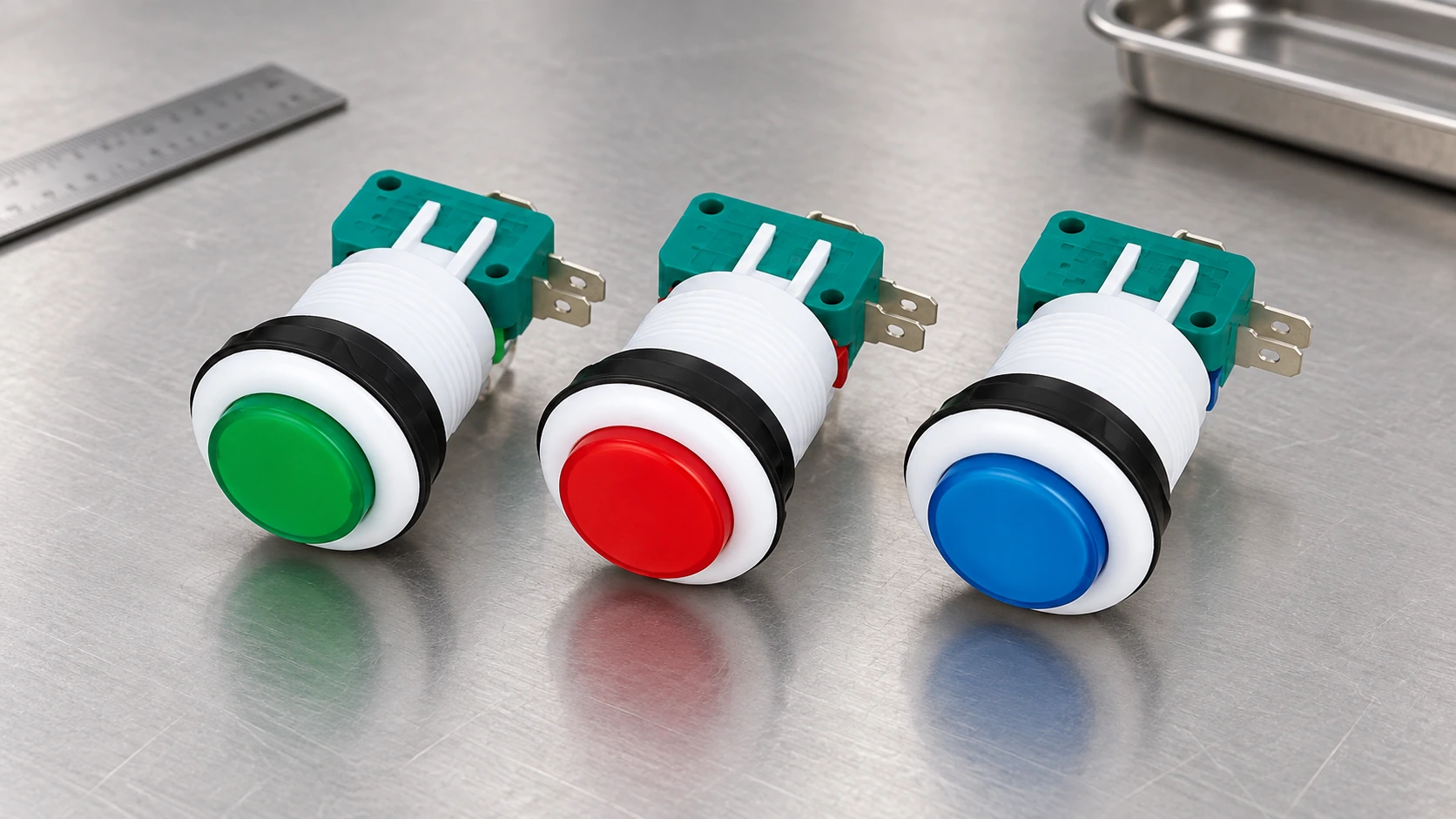
Separate the operator, control circuit and motor power circuit
A starter system has several different parts that are often all called a “starter switch.” The front pushbutton is the operator a person presses. Its contact set changes an electrical control signal. A relay or magnetic starter coil receives that control signal and changes the state of the starter’s power contacts. Those power contacts connect or disconnect the motor circuit under the starter’s design and ratings. An overload device, short-circuit protection, disconnect and enclosure have their own roles.
This distinction matters when purchasing. A panel-mount pushbutton may be suitable for a low-energy PLC input or a control-circuit path but not for switching motor current directly. A manual motor starter is a different assembly that can include a switching mechanism and overload protection. Do not treat an operator button, contact block, contactor or manual starter as interchangeable simply because each can be described with the words “push button” or “switch.”
El Capítulo de BCcampus sobre el control motor básico describes pushbuttons as momentary contacts used in control circuits and distinguishes them from power-rated switches. Use the chosen product’s own drawing and ratings for the actual equipment; a general textbook does not certify a particular LEMA model for a motor starter.
Understand a three-wire Start/Stop control arrangement
A three-wire magnetic-starter arrangement is a common way to use momentary Start and Stop pushbuttons. At a high level, a normally closed Stop contact is in the control path. A normally open Start contact provides the momentary start command. An auxiliary contact associated with the starter can maintain the coil command after the Start button is released. When the Stop path opens, or when control power is lost, the coil drops out and the holding contact opens. Restart then requires a new Start action in this basic topology.
This behavior is often called low-voltage protection in motor-control teaching materials. It describes a control behavior, not a complete machine-safety rating and not a guarantee about every circuit containing a start/stop button. The actual schematic, overload device, control supply, interlocks, drive logic and applicable rules determine the behavior of the installed system. For a conceptual walkthrough, see the BCcampus three-wire manual-circuit lesson.
| Pregunta de diseño | Common control-circuit role | What to verify for the actual machine |
|---|---|---|
| How is a momentary Start command recognized? | A normally open contact may close while the operator is pressed. | Rest and operated states, contact code, PLC or coil input, terminal drawing and control voltage. |
| How is a Stop command represented? | A normally closed contact may open when pressed in a basic three-wire arrangement. | Stop priority, wiring supervision, circuit fault behavior and the approved control narrative. |
| How does the starter remain energized? | A starter auxiliary contact may maintain the control path after Start is released. | Auxiliary-contact availability, coil logic, overload contact and restart behavior after power loss. |
| Is the button itself switching the motor? | Usually not in a magnetic-starter control station. | Motor power contacts, starter rating, protective devices and the exact product’s permitted electrical duty. |
| Is this a protective function? | A general pushbutton does not become a safety device because of its color or position. | Risk assessment, required safety performance, safety-rated components and validation of the complete system. |
The table summarizes common patterns for recognition, not a wiring diagram for a particular installation. Controls can vary by jurisdiction, machine type, control voltage, drive and required fault response. Do not copy a generic online circuit into production without review by the responsible electrical designer.
Choose the button’s contact arrangement from the logic
Write down the machine state when the operator is not touching the button and the state while the operator is pressing it. Confirm whether the selected contact is normally open, normally closed or a combination, and identify every terminal from the manufacturer’s diagram. “Normal” refers to the defined unactuated state; it does not mean that the machine is in a safe condition or that the motor is stopped.
Button color is a separate visual convention. Green, red, yellow, blue and black caps can indicate functions under a site standard or machine specification, but a color alone does not identify the contact state or certify the function. The IEC 60947-5-1 scope covers electromechanical control-circuit devices and switching elements. Check the currently applicable standard and the equipment’s requirements rather than assuming a color, shape or contact arrangement is universal.
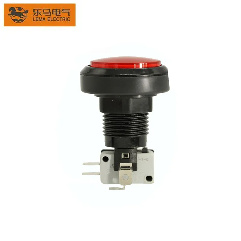
Match the button and contact to the starter input
The contact that operates a starter coil may carry a different duty from a low-current logic input. Check the control voltage and current, AC or DC supply, coil characteristics, switching frequency, expected electrical life and any minimum-load condition. A pushbutton contact rating for a resistive load should not automatically be used for an inductive coil. If an interface relay or PLC input is part of the design, verify the whole signal path and its protection.
Do not treat the contact block’s maximum current as a motor horsepower rating. Motor starting current, switching category, line voltage and protective coordination belong to the starter and power circuit. If someone proposes putting motor current through a small panel button, stop and review the exact manufacturer’s rating and the equipment design before purchase or installation.
For LEMA, the PBS Series product page provides genuine product examples, but the visible image does not establish a specific model’s starter coil compatibility, load rating, separate contact-block architecture or safety approval. Request the exact model code, drawing, contact form and written electrical rating. If the page does not identify the duty required by the machine, treat that application as unverified rather than inferring performance from appearance.
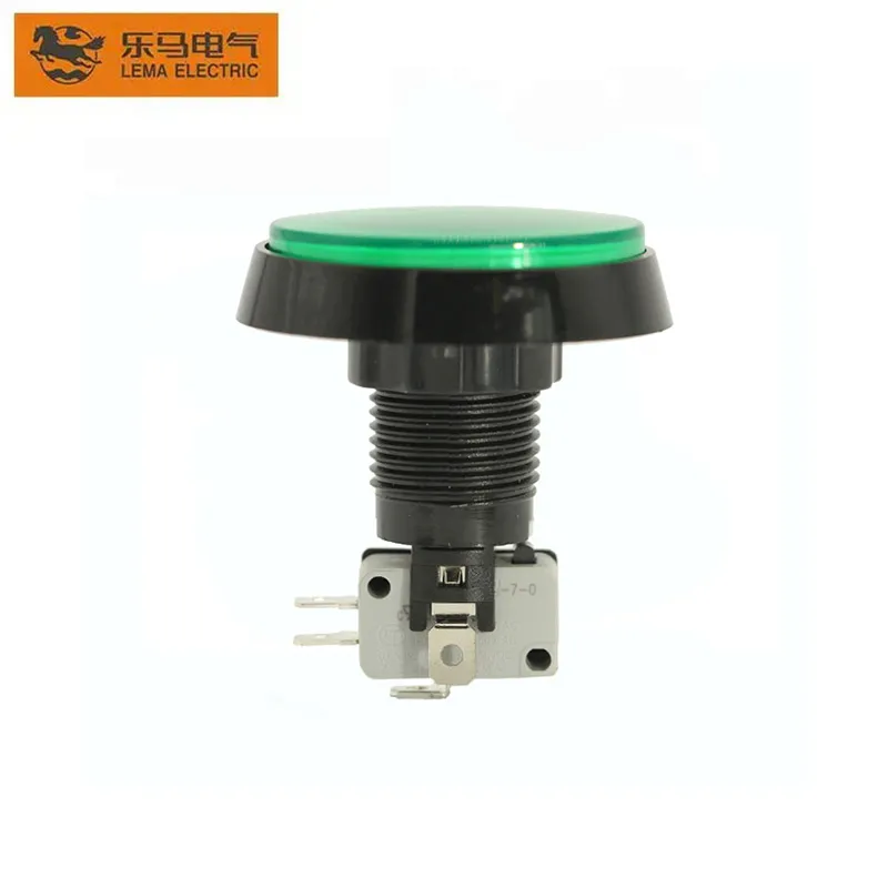
Check two-wire and three-wire control before choosing
A two-wire control commonly uses a maintained device whose state remains in place, such as a selector, thermostat or other pilot device. A three-wire start/stop circuit commonly uses momentary buttons with a starter auxiliary contact to hold the coil after the Start button is released. These are different control behaviors. They affect what happens after a power interruption and whether the machine may restart automatically when control power returns.
That difference is an important design decision, but it is not an instruction to choose one topology in every application. Restart behavior, remote stations, interlocks, emergency-stop circuits and machine modes must follow the approved control narrative and risk assessment. The exact pushbutton style—momentary, maintained, key-operated or selector—must align with that narrative.
Keep the operator button separate from machine safeguarding
A normal Stop pushbutton is a command device in a control sequence. It is not automatically an emergency stop, guard interlock or risk-reduction measure. OSHA’s general machine-guarding rule requires protection from machine hazards where workers are exposed. The specific safeguarding method depends on the machine, risk assessment and applicable jurisdiction. A starter control button cannot replace a required physical guard or a validated safety-rated circuit.
Do not use a general-purpose pushbutton as the sole means of making maintenance safe. Service work requires the site’s hazardous-energy procedure and qualified personnel. A pushbutton does not isolate all electrical, pneumatic, hydraulic, stored mechanical or other energy sources. If the control sequence includes protective functions, use the devices and architecture approved for those functions and validate the complete system.
Prepare a motor-starter pushbutton request for quotation
- Identify the motor starter or contactor model and the control-circuit supply.
- Describe the control behavior: momentary or maintained, Start, Stop, Reset, Jog or selector function.
- Specify contact state at rest and when operated, number of circuits and terminal arrangement.
- State the control voltage, coil or PLC input, load type, switching frequency and required life.
- Give panel cutout, operator diameter, mounting depth, enclosure and cable or terminal constraints.
- List the required environmental conditions and any approved standards or safety functions.
- Ask for the current drawing and written confirmation that the exact operator/contact configuration meets the application.
For related information, see LEMA’s Guía de selección de botones industriales, el contact-block compatibility guide, el 24 V PLC-interface article y el momentary-versus-maintained selection guide. They cover complementary decisions; this article focuses on the button’s role in motor-starter control rather than replacing those topics.
Watch a three-wire starter station explained
The video below is an independent educational walkthrough of a three-wire motor-starter circuit and its on/off push-button station. It demonstrates general circuit principles, not LEMA product wiring or a safety certification. Use the machine’s approved schematic and component documentation for the real installation.
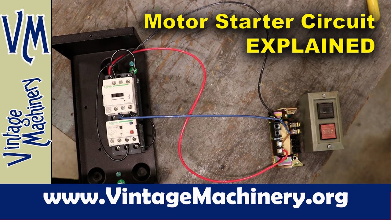
Watch the motor-starter push-button station explanation on YouTube.
Preguntas frecuentes
Does a pushbutton switch normally carry the motor’s full current?
Usually not in a magnetic-starter control station. The pushbutton sends a control signal, while the starter’s power contacts switch the motor circuit. Only use a button directly on a load when the exact product is rated for that duty.
Why does a three-wire starter use a Stop button that is normally closed?
In a common three-wire arrangement, the momentary NC Stop contact opens the control path when pressed. The approved machine schematic determines the actual circuit and its required fault behavior.
Can a red or green button tell me whether the contact is NO or NC?
No. Color is a visual convention. Check the contact code and terminal diagram for the exact button model.
Can a standard pushbutton be used as an emergency stop?
Do not assume so. An emergency-stop function requires components and a validated control system appropriate to the machine risk assessment and applicable requirements.