
To test a push button switch with a multimeter, first establish a safe de-energized condition and isolate the contacts from other circuit paths. Identify the intended contact pair from the exact switch drawing, check the meter and leads, then record the reading with the button released, pressed and released again. A normally open pair should change from open to closed when operated; a normally closed pair should do the reverse, according to its documented mechanism. This procedure checks contact-state behavior. It does not prove load capacity, endurance, safety certification or the complete machine response.
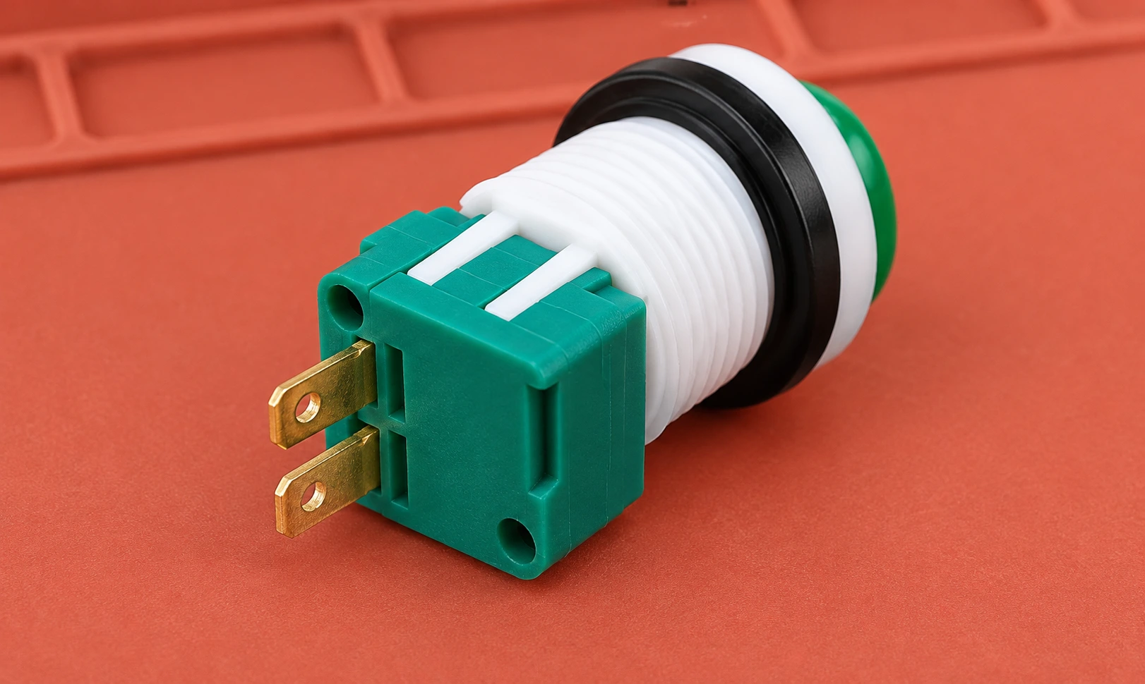
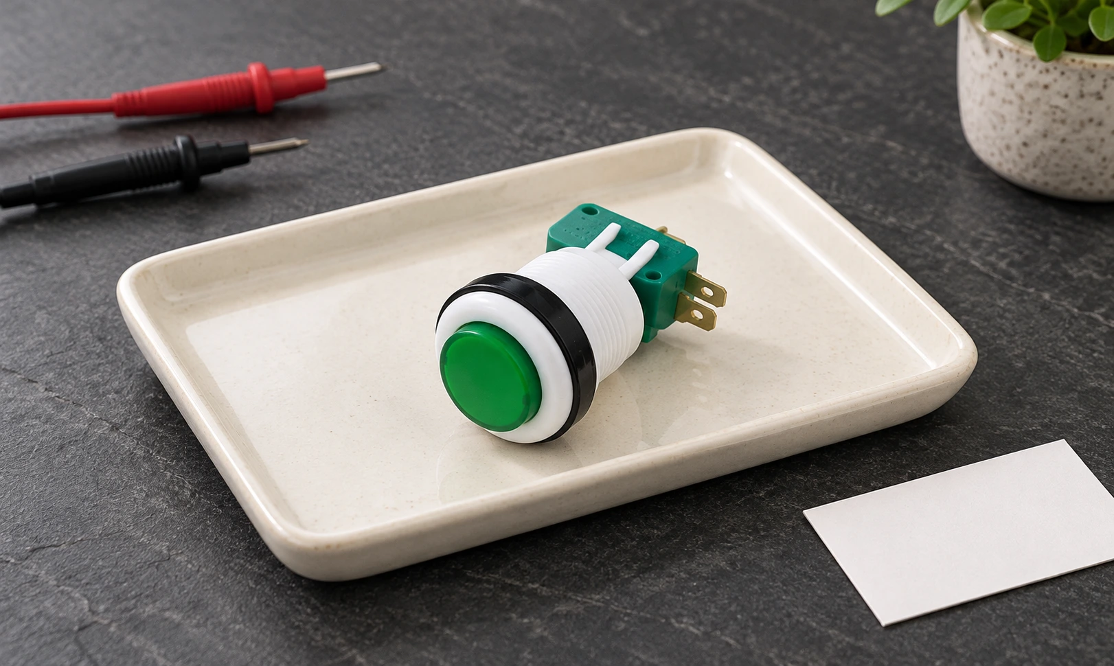
This guide is a bench measurement and recordkeeping workflow for ordinary discrete push button contacts. Electronic touch buttons, illuminated assemblies and protective devices may require different procedures. The product illustrations show a LEMA PBS example for identification; they are not universal pin-number diagrams or instructions for live testing.
Define the question before selecting a meter function
Decide whether you need to identify a contact pair, confirm released and operated states, investigate an unstable reading or compare a sample against an approved requirement. These are related questions but have different conclusions. A continuity test can reveal an open connection or a state change. It cannot establish the correct electrical duty for a motor, determine an endurance rating or approve a protective control.
For a machine that fails to respond, use the separate push button troubleshooting guide to distinguish actuator, wiring and controller faults. This article focuses on repeatable isolated measurements. Do not remove a working button from its circuit merely because the controller’s response is unfamiliar; start with the equipment schematic and documented command sequence.
Have the exact order code, terminal drawing and action description available. Identify whether the operator is momentary or maintained. A maintained operator may keep its state after release, so its expected measurement sequence differs. Record the required reset action rather than assuming that every button should spring back electrically and mechanically.
Establish safe isolation and remove parallel paths
Follow the equipment’s approved hazardous-energy procedure. A stop button or an open switch contact does not establish energy isolation. Account for every relevant supply and stored energy. Competent personnel must verify a safe condition before connecting resistance or continuity test leads. Do not switch a meter to resistance mode while its probes remain connected to an energized circuit.
The government text of 29 CFR 1910.147 on hazardous-energy control provides an authoritative reference for covered servicing activities. HSE’s electrical test equipment guidance provides additional background on test equipment and working practices. The actual workplace and equipment requirements govern the operation.
Disconnect the relevant contact sufficiently to prevent another branch from providing an alternative path through a lamp, relay, input module or other component. Label conductors and preserve the original connection record before removal. If isolation would affect a protective circuit, use its approved servicing and validation procedure rather than applying an ordinary bench checklist.
Check the meter and lead baseline first
Read the instrument manual and use the specified terminals and function. Inspect the leads and probe insulation. With the probes safely away from the equipment, compare the meter’s open-probe indication with the indication when its tips are touching. Record the lead baseline when making resistance comparisons. A faulty lead or wrong input jack can make a working contact appear open.
Different meters use different continuity thresholds and response times. A beep means the measured path meets that instrument’s indication rule, not that the contact has zero resistance. A display such as OL also has an instrument-specific meaning, often an open or out-of-range indication. Confirm it in the manual rather than assigning one interpretation to every display.
El Fluke 88 V user manual includes switch continuity testing and instrument instructions. Use it as an example of why the actual meter documentation matters, not as a universal specification for all meters. This guide intentionally sets no generic resistance pass limit for every push button.
Identify contact pairs without guessing from pin count
A two-terminal discrete switch may provide one contact pair, but more terminals do not automatically identify their function. Some assemblies provide several contacts; others add lamp or electronic connections. Terminals that look similar can belong to different circuits. Work from the order-code-specific drawing and distinguish the contact portion from any indicator circuit.
For an ordinary changeover contact, the common terminal is associated with alternative contact states. Verify that arrangement from documentation before taking readings. The normally open versus normally closed guide explains the defined normal-state distinction. Normal must refer to the specified mechanism condition, not simply to whichever position the operator happened to leave the button in.
If the diagram is missing, measurements may help characterize an isolated sample, but the record remains a measured observation rather than a supplier-approved terminal assignment. Request the drawing before production wiring or procurement approval. Do not infer compatibility with another manufacturer’s block from a similar number of terminals or a similar housing colour.
Record a complete state sequence
Place the probes on the documented pair and establish stable contact without bridging adjacent terminals. Record the released condition, operate the button normally, record the operated condition and then release or reset it as specified. Repeat the sequence enough to determine whether the observation is consistent under the approved check. Do not force the operator beyond its intended movement.
For a momentary normally open pair, the expected sequence is open, closed and open. For a momentary normally closed pair, it is closed, open and closed. A maintained mechanism may retain its second state until the specified reset. Where several contact pairs exist, record each separately; one successful pair does not prove the function of all others.
| Documented arrangement | Released or initial state | Operated state | Return or reset check |
|---|---|---|---|
| Momentary normally open pair | Open path | Closed path | Returns to open after release |
| Momentary normally closed pair | Closed path | Open path | Returns to closed after release |
| Maintained contact | Defined initial state | Defined alternate state | Follow the specified reset action |
| Multiple independent pairs | Record each pair | Record each pair | Compare each result with its drawing |
| Indicator terminals | Separate from contact test | Separate from contact test | Use the indicator’s specified procedure |
This is a qualitative state table based on the documented contact function. Enter actual instrument readings alongside it in the work record. Do not convert the words closed and open into a universal numerical threshold. The approved component requirements and test conditions determine whether a particular resistance measurement is acceptable.
Investigate inconsistent readings without overclaiming
When a reading changes unexpectedly, first check probe contact and lead stability. Move the probes only under the safe test condition and repeat the observation. A slipping tip, oxidized external terminal or damaged lead can produce an intermittent display without an internal mechanism fault. Preserve the original reading and note what changed before drawing a conclusion.
Then compare the actuator movement with the observed contact state. A sticking operator, loose assembly or incomplete press can create a different sequence from the intended one. Test in the installed mounting arrangement if the approved method requires it, since panel stress can affect behavior. Do not treat an unmounted bench pass as proof that the completed panel will behave identically.
A handheld meter usually cannot characterize very short contact-bounce events. Repeated beeps or a stable display do not establish a bounce duration. Where input timing matters, use a suitable measurement and validation method. The push button debounce guide addresses the separate signal-conditioning question.
Keep LED checks and load approval separate
An illuminated button can have a working contact and a failed indicator, or an illuminated indicator and a failed contact. Its lamp circuit may include electronics or polarity-sensitive parts. Do not apply a guessed supply or use the contact continuity procedure as an indicator acceptance test. Follow the indicator’s specified voltage, connections and verification method.
Likewise, an ordinary continuity result does not establish contact resistance with the accuracy required for a low-resistance acceptance test. Lead resistance, contact pressure and the instrument method influence the observation. Where a specific low-resistance requirement exists, use the approved measurement setup and record its conditions. Avoid reporting an approximate handheld reading as a precision production result.
Electrical load suitability requires the specified rating and application evidence. A contact that closes at the meter’s small test stimulus may still be unsuitable for the intended switching duty. Do not demonstrate capacity by connecting an improvised load to a suspect assembly. If replacement is necessary, use the push button replacement checklist to compare the complete documented function.
Produce a useful acceptance record
Record the sample identity, drawing revision, contact pair, action type, instrument, lead baseline, each observed state and any inconsistent behavior. Include the mounting condition and relevant test limitations. State exactly what passed: for example, the isolated pair followed its documented state sequence. Keep broader load or machine approval conclusions out of that entry unless their required checks were actually performed.
For a LEMA PBS series enquiry, send the desired action and contact arrangement with the equipment interface requirements. Request exact-variant documentation. A visual family reference does not establish an interchangeable contact block, an indicator supply or a protective-function approval. Traceable observations and precise questions are more useful than the unqualified statement that the button beeps.
Further learning
This independent educational video provides background for the checks discussed above. It does not identify the terminals of the illustrated LEMA product or replace the equipment manufacturer’s approved procedure.
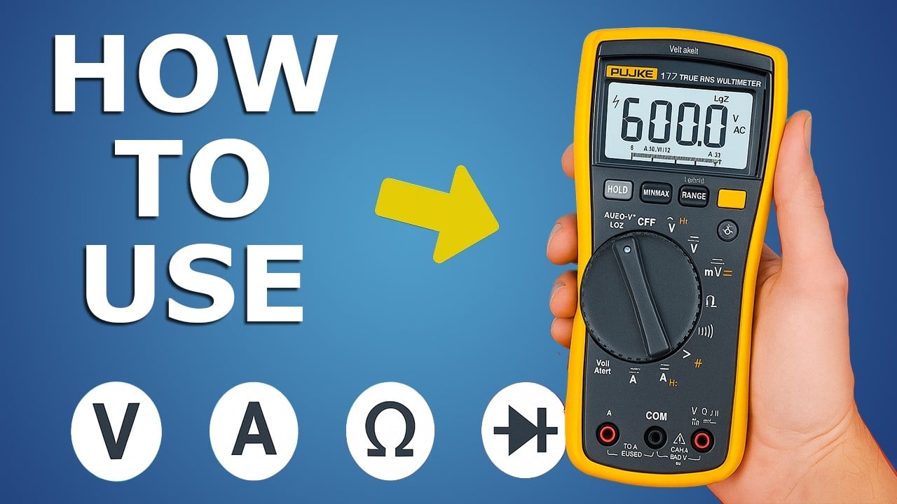
Watch How to use a multimeter like a pro! The Ultimate guide — The Engineering Mindset
Preguntas frecuentes
Does a continuity beep mean a push button is good?
It only confirms the meter’s continuity indication under that test condition. Check the documented state sequence and perform any additional required tests before approval.
Can I test resistance while the button is connected to a powered machine?
No. Establish the approved safe de-energized condition and isolate the tested path before resistance or continuity measurements.
Why can an open contact still give a reading?
Another circuit branch or poor test setup may affect the result. Isolate the intended pair and check the instrument and leads before interpreting it.
Can a multimeter measure push button contact bounce?
A basic continuity display generally cannot establish short bounce timing. Use a suitable measurement method when timing is part of the acceptance requirement.