
Dental Foot Switch Selection: A Checklist for Equipment OEMs
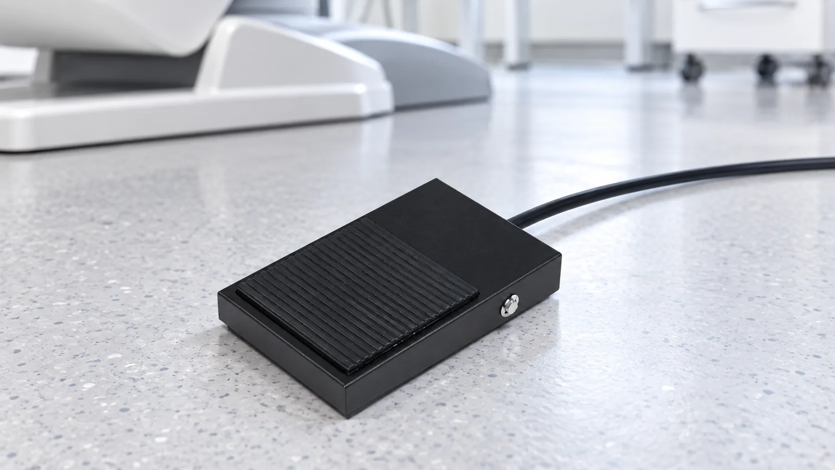
A dental foot switch should be selected from the function and interface outward. First identify what the pedal must control—chair movement, an instrument, coolant, or another function—then confirm whether the unit expects a pneumatic signal, an electrical contact, a proportional input, or a combination. The pedal’s shape alone cannot establish compatibility. For an OEM or replacement project, confirm the exact circuit, operating state, connector, cable, mounting, environmental needs and system-level safety evidence before approving a sample. LEMA’s LF Series page lists medical apparatus among possible applications, but it does not identify a specific dental-unit model or establish medical-device certification for every LF variant.
Start with the function, not the pedal appearance
“Dental foot switch” can refer to several different devices. A pedal may start a handpiece, vary its speed, move a chair, select wet or dry operation, or command another accessory. Some units combine several functions in one control. These actions can use different electrical or pneumatic interfaces even when the pedals look similar.
Write down each requested output separately. Record whether the action is hold-to-run or latched, whether the signal varies with pedal travel, and what the equipment should do when the operator releases the pedal, the cable is disconnected, or control power is restored. Do not assume that a single-contact on/off pedal can replace a proportional speed control or a multi-function chair controller.
Distinguish pneumatic, electrical and hybrid controls
Dental units can use air pressure, electrical contacts or a combination of signals. The control architecture is equipment-specific. In an air-operated pedal, pedal motion changes a pneumatic signal. An electrical pedal may close or open a contact, or provide a variable signal through electronics in the pedal or equipment. A hybrid design can use both pneumatic and electrical functions. A cable count or housing shape is not enough to tell which system is present.
| Control approach | What the pedal may send | What the OEM must verify |
|---|---|---|
| Pneumatic | Air pressure or flow changes with pedal movement | Tube count, port arrangement, pressure range, return behavior and the unit’s valve configuration |
| Electrical contact | A discrete open/closed circuit | Normally open or normally closed state, voltage, current, load type, contact form and connector pinout |
| Electrical proportional | A variable electrical signal tied to pedal travel | Signal type and range, reference supply, controller input, calibration method and fault response |
| Hybrid | More than one pneumatic or electrical channel | Every channel separately, including isolation, cable routing and simultaneous-function rules |
For broader context, LEMA’s pneumatic versus electrical foot-switch guide compares the basic control methods. A dental-unit manufacturer’s current schematic and service instructions remain the authority for the specific system.
Confirm contact behavior and electrical duty
If the dental unit accepts a mechanical contact, ask for the required contact arrangement and unactuated state. Confirm whether the circuit expects a momentary or maintained action, a single or multiple poles, and a discrete command or a signal conditioned by the unit. The terms “NO” and “NC” describe the contact state before the actuator is pressed; they do not specify the electrical load the contact can switch.
Ask the equipment designer for the control-circuit voltage, steady current, switching frequency, load type and any required electrical-life target. A signal input, relay coil and powered motor are different loads. An AC rating should not be assumed to apply to DC, and an ampere marking alone does not establish suitability for every load. Compare the exact model datasheet and circuit requirements. See the related foot-switch contact-rating guide for the questions to document.
Match the connector, cable and mechanical installation
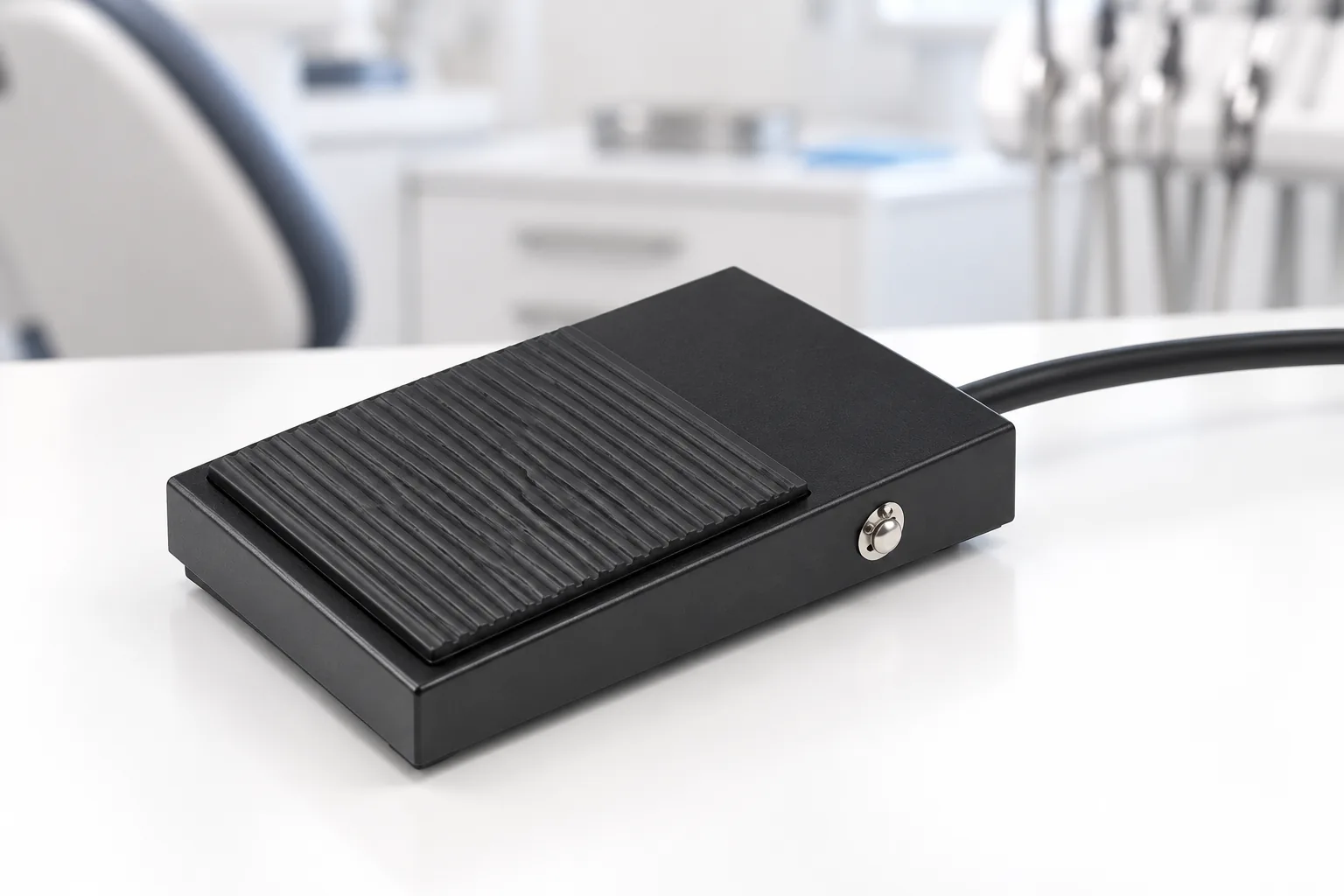
Many replacement problems come from a mismatch at the interface rather than a failed switch. Obtain the mating connector drawing, number of conductors, pin assignment, shield or ground requirements, cable length and strain-relief method. Do not copy wire colors from another chair or assume a connector with the same number of pins has the same function.
Check the pedal’s mounting footprint, fastener locations, overall height, travel, actuation force and return behavior against the floor space and operator posture. The pedal must remain stable under use and must not slide into an unintended position. If the operator needs distinct left/right or up/down actions, confirm whether the design uses separate pedals, a rocker, a lever or a multi-axis control. LEMA’s single-pedal versus dual-pedal guide can help define that control requirement before requesting samples.
Validate the cleaning and operating environment
Describe the real environment instead of asking only for a “waterproof” pedal. Include routine cleaning agents, wipe-down frequency, possible spills, dust, temperature, cable flexing and how the pedal is stored. A housing’s ingress rating—when a particular model has a published rating—does not by itself confirm compatibility with disinfectants, repeated chemical exposure or a dental unit’s required cleaning protocol. Confirm those conditions against the exact material and test documents.
Inspect the full cable and connector path, not just the pedal body. Fluid can enter at a connector, seam or cable exit even when a housing is sealed. Confirm the intended cleaning method and whether the pedal is meant to be wiped, immersed or kept away from liquid. Never infer immersion suitability from a photograph or a general product-family description.
Keep component selection separate from medical-device approval
IEC 60601-1 addresses basic safety and essential performance for medical electrical equipment. IEC notes that particular equipment may also be governed by collateral or product-specific standards, so the general standard is not used alone where those requirements apply. The FDA 510(k) summary for one dental unit, for example, describes electrical safety and EMC evaluation of the system including its foot controls. That is evidence about that device’s assessment, not a certification or approval for a different pedal.
Die LEMA LF Series Foot Switch page lists applications that include medical apparatus, and it provides multiple product variants. It does not say that every model is a dental control, specify a compatible chair, or establish IEC 60601-1 compliance. The IEC 60601-1 standard addresses basic safety and essential performance for medical electrical equipment; the required collateral or particular standards depend on the device. The FDA 510(k) summary for one dental unit, for example, describes system-level safety and EMC testing that included foot controls. That record applies to that device, not to a different pedal. Treat the LF pedal as a component candidate only after the dental-equipment manufacturer confirms the intended interface and completes the required system-level evaluation. A component photo, a product-family application list or a supplier’s general statement cannot replace that process.
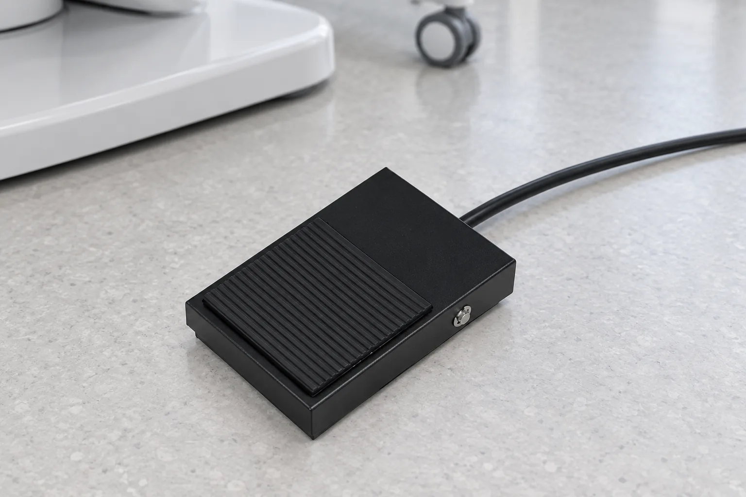
For service work, also distinguish a control pedal from an energy-isolating device. OSHA’s hazardous-energy rule says that push buttons, selector switches and other control-circuit devices are not energy-isolating devices. Follow the equipment maker’s service procedure and applicable workplace requirements; releasing the pedal is not a substitute for safe isolation.
Use a sample-approval checklist
Before approving a dental foot switch, capture the following in the project specification:
- Function controlled and whether the output is pneumatic, discrete electrical, proportional or hybrid.
- Momentary or maintained action, contact form and required unactuated state.
- Control-circuit voltage, current, load type, switching frequency and required life.
- Connector drawing, pinout, cable length, shielding, grounding and strain relief.
- Mounting envelope, pedal travel, actuation force, return behavior and slip resistance.
- Cleaning chemistry, wipe-down method, moisture exposure and storage conditions.
- System-level safety, EMC, risk-management and applicable regulatory evidence required by the dental-device OEM.
- Test plan for continuity or signal range, release behavior, cable flexing, repeated operation and any fault-state response.
Test the sample with the approved equipment interface and the OEM’s documented acceptance criteria. A successful bench continuity test proves only the tested contact path under those conditions. It does not establish compatibility with the whole dental unit, safe patient use or regulatory compliance. If an operator guard is part of the machine design, treat the pedal hood and the rest of the safeguarding system as separate decisions; see LEMA’s guarded foot-switch selection guide.
For LEMA LF-series inquiries, send the intended function, control diagram, connector drawing, cleaning environment and required approvals along with the model proposal. LEMA’s product page describes selectable contact forms and cable customization, but buyers should request a model-specific drawing and written confirmation before a dental-device design release.
Watch a model-specific dental pedal service example
This third-party tutorial shows diagnosis and replacement of a DCI 6310 dental foot pedal. Its steps and parts are model-specific; they are not LEMA instructions and do not establish compatibility between different brands. Use the applicable service manual and the dental-equipment OEM’s electrical and safety procedures.
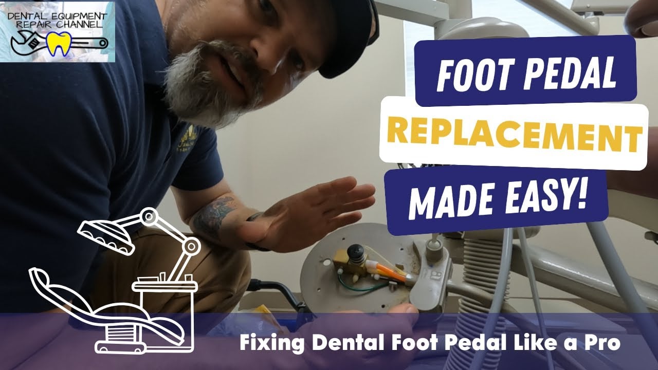
Watch the dental foot pedal repair demonstration on YouTube.
Häufig gestellte Fragen
Are dental foot switches pneumatic or electrical?
Both types are used, and some pedals combine functions. Identify the signal expected by the specific dental unit from its schematic and service documentation.
Can a general foot switch replace a dental chair pedal?
Only if the dental-equipment OEM confirms the pedal’s function, interface, connector, ratings, mechanical fit and system-level evaluation. Similar appearance is not proof of compatibility.
Does an LF-series application mention prove medical-device certification?
No. LEMA’s LF page lists medical apparatus among possible applications, but that does not establish a model’s certification or approval for a dental unit. Request the exact model documents and obtain the system manufacturer’s acceptance.
Does releasing the pedal isolate the dental unit’s energy?
No. A pedal is an operating control, not an energy-isolating device. Follow the equipment’s approved service and isolation procedure.