LEMA NEWS CENTER

News & Blog

News Center

SPDT Switch Symbol, Terminal Logic and Schematic Guide
Blog LEMA Electric

SPDT-Schaltersymbol, Klemmenlogik und Schaltplan-Leitfaden

Das SPDT-Schaltersymbol wurde zu einer Priorität, da die Google Search Console bereits reale Impressionen für dieses Thema auf LEMA anzeigt. Dieses Signal weist auf ein bestehendes Publikum hin, aber die vorherige Abdeckung der Website entsprach nicht vollständig der Fragestellung. Dieser Leitfaden verwandelt die Suchanfrage in einen praktischen Arbeitsablauf für Auswahl, Integration und Einkauf für Geräteentwickler, Schaltschrankbauer, Instandhaltungsteams und industrielle Einkäufer. Das SPDT-Schaltersymbol zeigt einen beweglichen Gemeinsam-Kontakt (COM), der entweder mit einem von zwei festen Kontakten verbunden werden kann. Es beschreibt die elektrische Logik und nicht die physische Ansicht eines echten Schalters. Ein Schema zeigt möglicherweise den Normal- oder unbestromten Zustand gemäß seiner Zeichnungskonvention, während die Rückseite eines Produkts das widerspiegeln kann, was eine Frontansicht vermuten lässt. Beschriften Sie die Drähte mit COM, NO und NC – oder Common, Schaltausgang A und Schaltausgang B – erst nach Überprüfung des Herstellerschemas und der Durchgangsprüfung. Ein SPDT kann Signale auswählen, Logik umkehren, alternative Ausgänge bereitstellen oder ein NO/NC-Paar für einen Steuerungseingang erstellen. Die Anwendungsansicht zeigt praktische Integrationspunkte für das SPDT-Schaltersymbol. Was das SPDT-Schaltersymbol in einem realen Design bedeutet: Eine nützliche Spezifikation beginnt mit dem Verhalten und nicht mit einem Katalogfoto. Schreiben Sie auf, was sich bewegt, was der Bediener oder die Maschine erreichen möchte, wann sich der elektrische Zustand ändern muss und was passieren soll, wenn ein Leiter sich öffnet oder das Gerät nicht zurücksetzt. Trennen Sie das Feldgerät von der Steuerungslogik: Ein Schalter meldet oder befiehlt einen Zustand, während das Relais, die SPS oder der Steuerstromkreis entscheidet, wie die Maschine reagiert. Ähnliche Produktfamilien enthalten oft mehrere Kontaktanordnungen, Betätigungsarten, Anschlussformen und Montageversionen. Der Familienname hilft beim Auffinden, definiert jedoch kein Produktionsteil. Verwenden Sie das vollständige Modellmodellsuffix, die revisionsgesteuerte Zeichnung und das Anschlussdiagramm....

Mehr lesen
Toggle Switch Hole Size and Panel Mounting Guide
Blog LEMA Electric

Größe der Kippschalter-Einbauöffnung und Anleitung zur Schalttafellemontage

Die Lochgröße für Kippschalter wurde zu einer Priorität, da die Google Search Console bereits reale Impressionen für dieses Thema auf LEMA anzeigt. Dieses Signal weist auf ein bestehendes Publikum hin, aber die vorherige Abdeckung der Website entsprach nicht vollständig der Frage. Dieser Leitfaden verwandelt die Suchanfrage in einen praktischen Auswahl-, Integrations- und Beschaffungsworkflow für Gerätetechniker, Schaltschrankbauer, Wartungsteams und industrielle Einkäufer. Die Lochgröße für Kippschalter ist keine universelle Zahl. Die erforderliche Öffnung richtet sich nach dem Gewindedurchmesser oder dem Rastgehäuse, der Verdrehsicherung, der Panelstärke, dem Scheibenstapel und der zulässigen Toleranz des jeweiligen Modells. Eine nominale Gewindebezeichnung ist keine fertige Ausschnittanweisung. Verwenden Sie die Herstellerzeichnung, messen Sie freigegebene Muster und fertigen Sie ein Testmuster aus dem realen Schaltschrankmaterial und der Beschichtung an. Überprüfen Sie den hinteren Freiraum für Anschlüsse und Verdrahtung, den Hebelfreiraum in jeder Position sowie den Werkzeugzugang für die Befestigungsmutter. Bei abgedichteten Modellen sind die Lochkante und die Dichtungskompression Teil des Eindringwegs. Ansicht der Anwendung, die praktische Integrationspunkte für die Lochgröße von Kippschaltern zeigt. Was die Lochgröße für Kippschalter in einem realen Design bedeutet Eine nützliche Spezifikation beginnt mit dem Verhalten, nicht mit einem Katalogfoto. Schreiben Sie auf, was sich bewegt, was der Bediener oder die Maschine zu erreichen versucht, wann sich der elektrische Zustand ändern muss und was passieren soll, wenn ein Leiter bricht oder das Gerät sich nicht zurücksetzt. Trennen Sie das Feldgerät von der Steuerungslogik: Ein Schalter meldet oder befiehlt einen Zustand, während das Relais, die SPS oder der Steuerstromkreis entscheidet, wie die Maschine reagiert. Ähnliche Produktfamilien enthalten oft mehrere Kontaktanordnungen, Betätigungsstile, Anschlussformen und Montageversionen. Der Familienname hilft beim Auffinden, definiert jedoch kein Produktionsteil. Verwenden Sie das vollständige Modell-Suffix, versionskontrolliert...

Mehr lesen
Toggle Switch Mechanism: How It Works and How to Select One
Blog LEMA Electric

Kippschalter-Mechanismus: Funktionsweise und Auswahl eines Schalters

Der Kippschaltermechanismus rückte in den Vordergrund, da die Google Search Console bereits echte Impressionen zu diesem Thema auf LEMA anzeigt. Dieses Signal deutet auf eine bestehende Zielgruppe hin, doch die bisherige Abdeckung der Website entsprach nicht vollständig der Fragestellung. Dieser Leitfaden wandelt die Suchanfrage in einen praktischen Workflow zur Auswahl, Integration und zum Kauf für Geräteentwickler, Schalttafelbauer, Wartungsteams und industrielle Einkäufer um. Ein Kippschaltermechanismus nutzt den Hebel, um interne Kontakte zwischen stabilen oder federrückstellenden Positionen zu bewegen oder einrasten zu lassen. Die Polzahl gibt an, wie viele separate Stromkreise gesteuert werden; die Schaltzahl gibt an, wie viele Wege jeder Pol auswählen kann. Die Bezeichnungen „ON-OFF“, „ON-ON“ und „ON-OFF-ON“ beschreiben festgestellte Positionen, während Klammern oder eine spezifische Notation im Datenblatt auf momentane Positionen hinweisen können. Die Schnappwirkung kann einen schnellen elektrischen Übergang bewirken, selbst wenn der Bediener den Hebel langsam bewegt. Bei der Auswahl muss die Kontaktfunktion auf die tatsächliche Schalttaflegeometrie, die Last, die Umgebungsabdichtung und die Benutzeroberfläche abgestimmt werden. Anwendungsansicht mit praktischen Integrationspunkten für Kippschaltermechanismen. Was ein Kippschaltermechanismus in einem realen Entwurf bedeutet: Eine nützliche Spezifikation beginnt mit dem Verhalten, nicht mit einem Katalogfoto. Halten Sie fest, was sich bewegt, was der Bediener oder die Maschine erreichen will, wann sich der elektrische Zustand ändern muss und was passieren soll, wenn ein Leiter unterbrochen wird oder das Gerät nicht zurückgesetzt werden kann. Trennen Sie das Feldgerät von der Steuerungslogik: Ein Schalter meldet oder gibt einen Zustand vor, während das Relais, die SPS oder der Steuerkreis entscheidet, wie die Maschine reagiert. Ähnliche Produktfamilien umfassen oft mehrere Kontaktanordnungen, Betätigungsarten, Anschlussformen und Befestigungsvarianten. Der Familienname erleichtert die Suche, definiert jedoch kein Serienbauteil. Verwenden Sie das vollständige Modellsuffix, eine revisionskontrollierte Zeichnung und ein Anschlussschema. Falls eine Auswahl...

Mehr lesen
Metal Push Button Switch: Durability, Panel Mounting and Selection Guide
Blog LEMA Electric

Metalldrucktastschalter: Haltbarkeit, Schalttafeleinbau und Auswahlleitfaden

A metal push button switch puts a harder bezel and actuator on the panel face, but front-panel durability still depends on material grade, gasket torque, impact test scope, and whether the switch behind the head can survive over-travel. This guide contrasts metal and plastic bezels, separates anti-vandal marketing from IK proof, maps abuse paths that bypass a metal face, and shows what to freeze on drawings and samples before colour or LED options enter the RFQ. Product-focused view supporting metal push button switch selection and panel integration. ContentsWhat a metal push button switch actually protects on the panelMetal bezel vs plastic heads for daily panel abuseAnti-vandal marketing vs IK and seal proof buyers should demandPanel wear: gaskets, torque, and fixing mistakes that defeat a metal headAbuse paths that bypass a metal bezelDrawing and sample proof before you trust a metal operatorSelecting PBS Series options after metal and abuse requirements are documentedFAQsWhat a metal push button switch actually protects on the panel A metal push button switch is not a single material specification. In procurement language it usually means the visible bezel and actuator are metal—often a stainless steel push button or nickel-plated brass in public-facing designs—so finger impact, key scratches, and daily panel wear hit a harder surface than a light-duty plastic panel switch head. That front hardness is real, but it is bounded. The Bezel / actuator pair can still dent, spin in the hole, or leak behind the panel if the gasket stack, nut torque, or rear switch path is wrong. Treat “metal” as a front-abuse decision, not proof of IK impact class, ingress sealing, or internal contact life. On a self-service kiosk, the metal ring is what...

Mehr lesen
Industrial Push Button Switch Selection: Environment, Duty and OEM Guide
Blog LEMA Electric

Auswahl von industriellen Drucktastenschaltern: Umgebungs-, Beanspruchungs- und OEM-Leitfaden

An industrial push button switch matches the panel zone first: dust, moisture, temperature swings, and vibration set the sealing and mounting stress before you compare actuators on a control panel. This article walks environment classification, mechanical cycle duty, electrical contact logic, LED illumination options, colour codes, and RFQ fields that keep procurement aligned with real machine conditions. Product-focused view supporting industrial push button switch selection and panel integration. ContentsHow Dust and Moisture Change Push Button SelectionTemperature Swings and Vibration at the Panel EdgeMechanical Cycle Duty: Matching Press Frequency to Switch LifeElectrical Interface Questions Before You Lock a Part NumberColour Codes and LED Options for Operator ClarityOEM RFQ Fields That Prevent Wrong-Spec DeliveriesSelect a PBS Industrial Push Button for Your Panel JobFAQHow Dust and Moisture Change Push Button Selection Dust and moisture decide whether a panel mount push button switch survives at the cutout, not just behind the bezel. Every hole is an ingress path, and IP rating thinking should follow the wettest zone on the control panel. Community builders note that adding buttons to a certified enclosure can change how the whole door performs against dust and spray. Important: Forum makers report that splashing water can press a tact switch unintentionally — wet zones need an actuator sealing plan, not only a higher IP label on a catalog line. Panel zone signal What to document in RFQ Why it matters for selection Dry indoor cabinet Dust class, occasional wipe-down Sealing focus on bezel gap and cable entry Humid or wash-adjacent Spray direction, chemical exposure Panel hole and actuator seal become primary Mixed door (display + buttons) Which functions sit in wettest area Example industrial operator families cite IP65 for dust...

Mehr lesen
SPDT KW10 Limit Micro Switch: Terminals, Actuation and Selection
Blog LEMA Electric

SPDT KW10 Mikroschalter: Anschlüsse, Betätigung und Auswahl

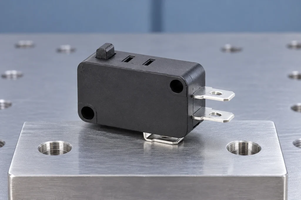
spdt kw10 limit micro switch became a priority because Google Search Console already shows real impressions for this topic on LEMA. That signal indicates an existing audience, but the previous site coverage did not fully match the question. This guide turns the query into a practical selection, integration and purchasing workflow for equipment designers, panel builders, maintenance teams and industrial buyers. A KW10-style SPDT micro switch normally exposes COM, NO and NC terminals. In the released state COM is connected to one throw; after actuation the snap mechanism transfers COM to the other. The family name does not guarantee identical terminal orientation, actuator force, life or electrical rating across suppliers and suffixes. Trace the markings on the exact component, confirm both states with an unpowered continuity test, and align the actuator so the target supplies adequate operating travel without crushing the plunger. Use the changeover contact to obtain the controller logic you need rather than assuming NO is always the preferred choice. Application view showing practical integration points for spdt kw10 limit micro switch. What spdt kw10 limit micro switch means in a real design A useful specification begins with behavior, not a catalogue photo. Write down what moves, what the operator or machine is trying to achieve, when the electrical state must change, and what should happen if a conductor opens or the device fails to reset. Separate the field device from the controller logic: a switch reports or commands a state, while the relay, PLC or control circuit decides how the machine responds. Similar product families often contain several contact arrangements, actuator styles, terminal forms and mounting versions. The family name helps discovery but does not define a...

Mehr lesen
Ultra Miniature Micro Switch Selection and Integration Guide
Blog LEMA Electric

Auswahl- und Integrationshandbuch für ultra-miniatür Mikroschalter

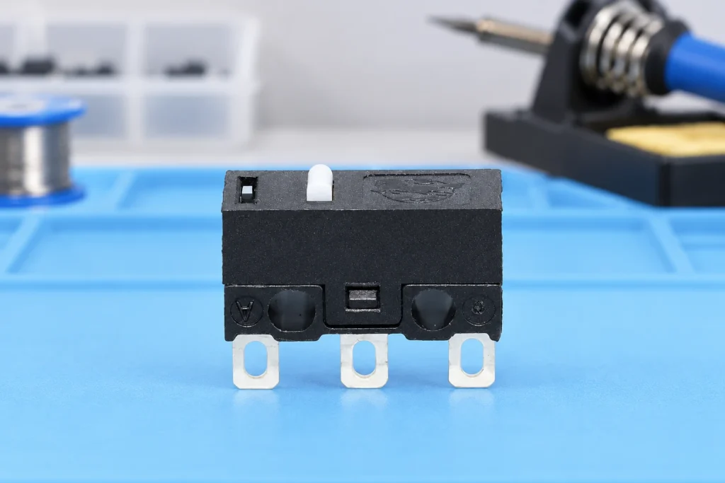
ultra miniature micro switch became a priority because Google Search Console already shows real impressions for this topic on LEMA. That signal indicates an existing audience, but the previous site coverage did not fully match the question. This guide turns the query into a practical selection, integration and purchasing workflow for equipment designers, panel builders, maintenance teams and industrial buyers. An ultra miniature micro switch saves volume only when its actuator, terminals and tolerance chain are designed together. Small housings usually leave less room for misalignment, soldering heat, board flex and excessive overtravel. Select the actuator by the motion presented by the product: a direct plunger suits controlled linear travel, while a lever can reduce operating force and absorb some approach variation. PCB models require special attention to hole pattern, seating, solder profile, cleaning process and mechanical support. The PCB should not become the stop that absorbs external impact. Application view showing practical integration points for ultra miniature micro switch. What ultra miniature micro switch means in a real design A useful specification begins with behavior, not a catalogue photo. Write down what moves, what the operator or machine is trying to achieve, when the electrical state must change, and what should happen if a conductor opens or the device fails to reset. Separate the field device from the controller logic: a switch reports or commands a state, while the relay, PLC or control circuit decides how the machine responds. Similar product families often contain several contact arrangements, actuator styles, terminal forms and mounting versions. The family name helps discovery but does not define a production part. Use the complete model suffix, revision-controlled drawing and terminal diagram. If any selection...

Mehr lesen
Push Button Colour Standards for Industrial Control Panels
Blog LEMA Electric

Drucktasten-Farbstandards für Schalttafeln

push button colour standards became a priority because Google Search Console already shows real impressions for this topic on LEMA. That signal indicates an existing audience, but the previous site coverage did not fully match the question. This guide turns the query into a practical selection, integration and purchasing workflow for equipment designers, panel builders, maintenance teams and industrial buyers. Push-button colour communicates expected action, but colour alone must never carry the entire meaning. A control panel should combine colour with a durable text label, symbol, position and consistent operating sequence. Red is commonly reserved for emergency or stop-related functions, green is commonly associated with starting or a normal condition, and yellow often signals an abnormal condition or intervention. The exact assignment depends on the applicable machine and market standards. Designers should document the selected convention, review local requirements, and prevent illuminated buttons from creating contradictory messages when lit and unlit. Application view showing practical integration points for push button colour standards. What push button colour standards means in a real design A useful specification begins with behavior, not a catalogue photo. Write down what moves, what the operator or machine is trying to achieve, when the electrical state must change, and what should happen if a conductor opens or the device fails to reset. Separate the field device from the controller logic: a switch reports or commands a state, while the relay, PLC or control circuit decides how the machine responds. Similar product families often contain several contact arrangements, actuator styles, terminal forms and mounting versions. The family name helps discovery but does not define a production part. Use the complete model suffix, revision-controlled drawing and terminal diagram. If...

Mehr lesen
Cam Limit Switch Working Principle, Setup and Selection Guide
Blog LEMA Electric

Funktionsweise, Einrichtung und Auswahlleitfaden für Nockenschalter

cam limit switch working principle became a priority because Google Search Console already shows real impressions for this topic on LEMA. That signal indicates an existing audience, but the previous site coverage did not fully match the question. This guide turns the query into a practical selection, integration and purchasing workflow for equipment designers, panel builders, maintenance teams and industrial buyers. A cam limit switch converts the angular position of a shaft or machine cycle into one or more electrical state changes. A rotating cam profile reaches an actuator at a chosen angle; the internal snap-action contact then changes state. The useful result is not simply “the cam touched the switch.” It is a repeatable switching window with adequate approach, overtravel and release margin. Setup therefore begins with the machine sequence: identify the earliest and latest acceptable switching angles, account for backlash and stopping distance, and make adjustments at reduced speed. Never use the switch body as the mechanical end stop. Application view showing practical integration points for cam limit switch working principle. What cam limit switch working principle means in a real design A useful specification begins with behavior, not a catalogue photo. Write down what moves, what the operator or machine is trying to achieve, when the electrical state must change, and what should happen if a conductor opens or the device fails to reset. Separate the field device from the controller logic: a switch reports or commands a state, while the relay, PLC or control circuit decides how the machine responds. Similar product families often contain several contact arrangements, actuator styles, terminal forms and mounting versions. The family name helps discovery but does not define a production...

Mehr lesen
Electric Foot Switch Selection Guide for Industrial Equipment
Blog LEMA Electric

Auswahlleitfaden für elektrische Fußschalter für Industrieanlagen

electric foot switch became a priority because Google Search Console already shows real impressions for this topic on LEMA. That signal indicates an existing audience, but the previous site coverage did not fully match the question. This guide turns the query into a practical selection, integration and purchasing workflow for equipment designers, panel builders, maintenance teams and industrial buyers. An electric foot switch gives an operator hands-free control, but it is not automatically a safeguarding device. Start by deciding whether the pedal sends a momentary start signal, maintains a circuit, jogs motion, or enables another control. Then document the normal and actuated contact states. A protected hood can reduce unintended access, while pedal shape, force, travel and floor stability determine whether the operator can use it repeatedly without awkward posture. For punching and similar machinery, the pedal must be evaluated as part of the complete control and guarding system. Do not rely on a foot control to keep hands away from a hazardous point of operation. Application view showing practical integration points for electric foot switch. What electric foot switch means in a real design A useful specification begins with behavior, not a catalogue photo. Write down what moves, what the operator or machine is trying to achieve, when the electrical state must change, and what should happen if a conductor opens or the device fails to reset. Separate the field device from the controller logic: a switch reports or commands a state, while the relay, PLC or control circuit decides how the machine responds. Similar product families often contain several contact arrangements, actuator styles, terminal forms and mounting versions. The family name helps discovery but does not define a...

Mehr lesen
12-Volt Power Socket Selection, Wiring and Protection Guide
Blog LEMA Electric

Leitfaden zur Auswahl, Verkabelung und Absicherung von 12-Volt-Steckdosen

12 volt power socket selection starts by defining the required machine or equipment function, then matching the electrical interface, mechanical mounting and environment to one exact component. This guide explains matching connector format, current demand, conductors, polarity, overcurrent protection, panel mounting and environmental exposure. “12 volt” is a nominal system label rather than a complete rating. Actual voltage range, current, duty cycle, polarity, connector geometry, conductor size and protective device coordination must be defined separately. Treat every terminal diagram, rating and dimension as model-specific, and validate the assembled system before production use. What the term means in an equipment design“12 volt” is a nominal system label rather than a complete rating. Actual voltage range, current, duty cycle, polarity, connector geometry, conductor size and protective device coordination must be defined separately. This distinction matters because search results often mix replacement parts, hobby wiring examples, complete control assemblies and bare industrial components. An OEM design needs a controlled specification rather than a visual match. Record the intended function in plain language, the normal and actuated states, the equipment supply, the connected load or controller input, and the consequence of a disconnected wire.The component should be considered together with its mating part, mounting structure, conductors, enclosure and controller logic. A correct component installed in an unsuitable cutout or connected to an incompatible load is still an incorrect system. When a seller offers several variants under one family name, request the variant drawing and do not transfer ratings or terminal positions from a neighboring model. Panel power socket used to review terminals and mounting. Verify the exact model drawing before production use. Selection decisions that prevent redesignDesign inputSelection questionVerificationNominal systemWhat voltage range exists during...

Mehr lesen
Limit Switch Accessories Selection and Integration Guide
Blog LEMA Electric

Auswahl- und Integrationshandbuch für Endschalterzubehör

limit switch accessories selection starts by defining the required machine or equipment function, then matching the electrical interface, mechanical mounting and environment to one exact component. This guide explains selecting levers, rollers, rods, brackets, glands, connectors and target cams while preserving mechanical and electrical compatibility. An accessory is part of the sensing system, not a cosmetic add-on. A lever length, roller diameter, bracket stiffness or cable gland can change operating force, travel, sealing, repeatability and service access. Treat every terminal diagram, rating and dimension as model-specific, and validate the assembled system before production use. What the term means in an equipment designAn accessory is part of the sensing system, not a cosmetic add-on. A lever length, roller diameter, bracket stiffness or cable gland can change operating force, travel, sealing, repeatability and service access. This distinction matters because search results often mix replacement parts, hobby wiring examples, complete control assemblies and bare industrial components. An OEM design needs a controlled specification rather than a visual match. Record the intended function in plain language, the normal and actuated states, the equipment supply, the connected load or controller input, and the consequence of a disconnected wire.The component should be considered together with its mating part, mounting structure, conductors, enclosure and controller logic. A correct component installed in an unsuitable cutout or connected to an incompatible load is still an incorrect system. When a seller offers several variants under one family name, request the variant drawing and do not transfer ratings or terminal positions from a neighboring model. Industrial limit switch and actuator hardware for accessory planning. Verify the exact model drawing before production use. Selection decisions that prevent redesignAccessory groupPurposeCompatibility checkActuator head or...

Mehr lesen