LEMA NEWS CENTER

News & Blog

News Center

12V Push Button Switch Control for Low-Voltage Circuits
Blog LEMA Electric

12V-Drucktastenschalter-Steuerung für Niederspannungskreise

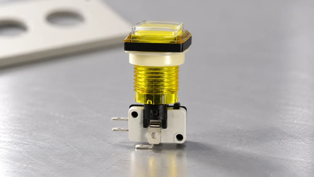
A 12V Push Button Switch: Low-Voltage Control Circuit Guide starts with one idea: the button is an operator contact on a low-voltage rail, not a universal power switch for every load. This article maps action type, NO/NC behaviour, control-versus-power staging, flyback protection, and logic isolation, then points to PBS Series ordering options when the front-panel part must match that plan. This figure shows a red PBS-series operator head used on low-voltage panels. ContentsWhat a 12V push button actually controlsMomentary vs maintained on a 12V control railNO, NC, and the common terminalControl path vs power pathInductive loads and flyback diodesWhen the button must talk to a controllerA practical checklist before you orderSelecting PBS Series for the panel frontFAQ What a 12V push button actually controls Electrically, a 12V push button switch only opens or closes contacts when an operator presses the actuator. In plain language, it is a human-operated gate on a control circuit, not a guarantee that the connected device can be powered through those contacts alone. On OEM panels, that distinction matters early. A jog button on a conveyor console may only need to pulse a control input, while a lamp test may share the same rail but a different contact job. Treat the button as a deliberate interface choice. Document which circuit it is allowed to interrupt, which rail it sits on, and what happens the moment the operator releases or presses again. Momentary vs maintained on a 12V control rail Momentary action keeps the changed contact state only while the button is held. Maintained / latching keeps the new state after release until the next deliberate actuation. The wrong choice turns a safe jog into an unintended...

Mehr lesen
24V Push Button Switch: PLC Input Interface Notes for OEM Panels
Blog LEMA Electric

24V-Drucktastenschalter: Hinweise zur SPS-Eingangsschnittstelle für OEM-Schalttafeln

A 24V push button switch becomes a PLC digital input when its dry contact closes a low-current 24V DC loop that matches the input module’s sinking or sourcing common. This article walks through that interface logic, the difference between passive buttons and PNP/NPN sensors, how illuminated operators split contact and lamp paths, and the commissioning checks OEM panels need before ladder logic is trusted. The panel scene below mirrors the operator-to-input topic of this guide. ContentsWhat a PLC Push-Button Interface Actually DoesSinking vs Sourcing Wiring for Dry-Contact ButtonsWhy Push Buttons Are Not Wired Like PNP/NPN SensorsIlluminated Operators: Contact Path vs Lamp PathCommissioning Checks Before You Trust the LadderOEM Notes When Specifying a Panel Push ButtonChoose PBS Series Push Button Switch for Panel InterfacesFAQ Use this list to jump through the interface notes. What a PLC Push-Button Interface Actually Does Sinking vs Sourcing Wiring for Dry-Contact Buttons Why Push Buttons Are Not Wired Like PNP/NPN Sensors Illuminated Operators: Contact Path vs Lamp Path Commissioning Checks Before You Trust the Ladder OEM Notes When Specifying a Panel Push Button Choose PBS Series Push Button Switch for Panel Interfaces FAQ References What a PLC Push-Button Interface Actually Does It closes a low-current 24V DC sensing loop into a discrete PLC input—nothing more exotic than that. A digital input module detects whether a field device is open or closed by watching voltage or current at the terminal. In a typical 24V control circuit, the push button, the input point, and the power supply form one continuous loop. When the operator presses the button, the contact finishes that loop and the module reports an ON state to the CPU. That current is small. Educational PLC...

Mehr lesen
Momentary vs Maintained Push Button: How to Choose
Blog LEMA Electric

Tastschalter vs. Rastender Drucktaster: Wie man wählt

A momentary vs maintained push button decision comes down to what should happen after the operator releases the control: a momentary button acts only during the press, while a maintained button keeps its changed state until it is actuated again. That physical difference should be decided before contact form, control logic, indicator feedback, ratings, mounting, and the final model are selected. It is an easy distinction to blur because both choices may look like ordinary panel buttons. Start with the operator's required action, then confirm how the circuit and selected model turn that action into a usable command. ContentsMomentary vs. maintained push buttons: the direct answerWhat changes when the button is released?Do not confuse action type with NO/NC contactsChoose by the job of the commandWho should retain the state: the switch or the control system?Decide whether visible feedback is requiredWhat to verify on the final modelExplore the PBS Series after defining the requirementFAQs Momentary vs. maintained push buttons: the direct answer Momentary action exists only while the button is actuated; maintained action, also called latching action, holds its changed state until the next actuation. The question is not which style is generally better. It is whether the panel command needs a short, deliberate input or a state that remains at the switch. Decision pointMomentary push button switchMaintained push button switch During the pressThe command changes while the operator holds the button.The command changes when the operator actuates the button. After releaseThe button returns and the temporary command ends.The changed switch state remains until the next actuation. Useful first questionShould this command exist only while pressed?Should this control retain its state without a continued press? Different operator outcomes follow from that...

Mehr lesen
Reviewing Held-State Logic Inputs for a Limit Switch
Blog LEMA Electric

Überprüfung der Eingaben für die Haltezustandslogik eines Endschalters

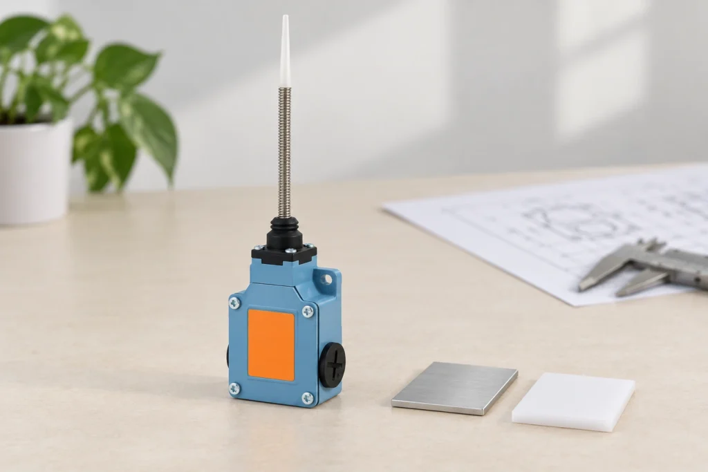
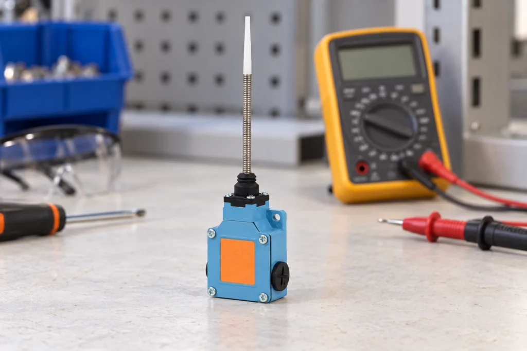
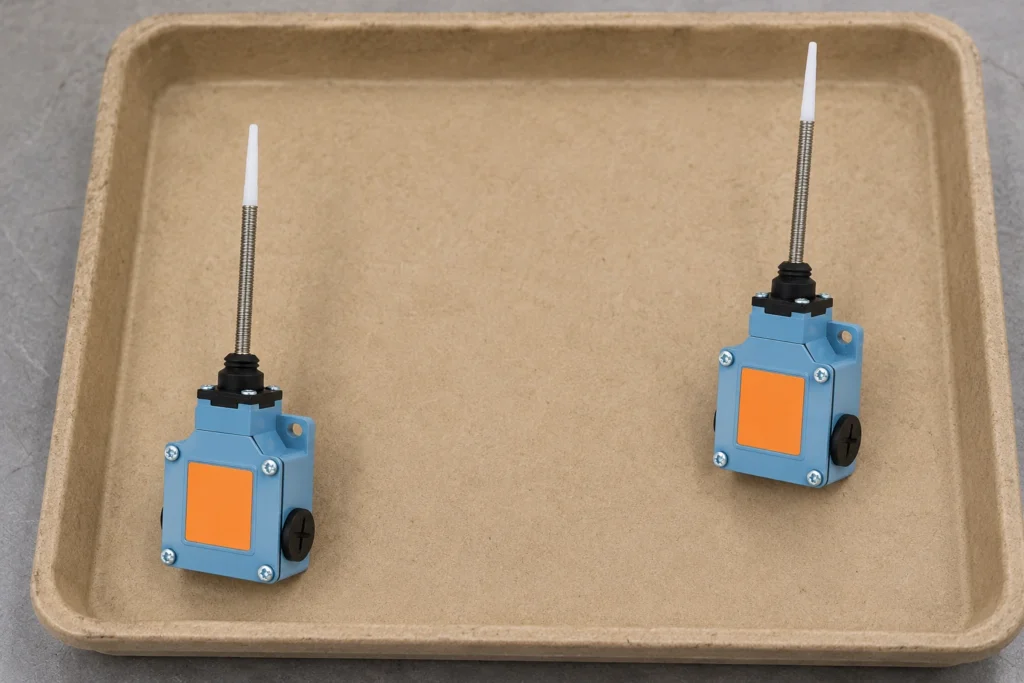
Held-state machine logic must be defined in the circuit and reset sequence before a limit switch is selected. Record the required state, reset path, operator access, mounting and verification conditions in the inquiry. Important: actuator shape or a generic switch description does not prove a model latches, supports a specific circuit, rating, approval or life. Source note: use selected-model documentation and IEC 60947-5-1 scope before release. - FAQ ContentsPart 1. What is held-state logic?Part 2. Which state and reset inputs should be documented?Part 3. How should circuit behavior be recorded?Part 4. Which mounting and service details matter?Part 5. Why does a general guide not prove model behavior?Part 6. What should be validated before release?Part 7. How can LEMA support an inquiry?Part 1. What is held-state logic? It describes a required machine state that remains defined until the documented reset condition occurs. The schematic and operating sequence, rather than a product name, define the intended behavior. Start at the LEMA Limit Switch product line once the control sequence is written. Part 2. Which state and reset inputs should be documented? State the triggering event, required held condition, reset method, reset location, operator instructions and access restrictions. Include a sequence diagram or control drawing with the request. InputDocumentRFQStateTrigger and required held conditionYesResetMethod, location and operator accessYesInterfaceCircuit and mounting contextYes Part 3. How should circuit behavior be recorded? Provide the drawing, state transition, required response, wiring method and interface to the machine controls. Keep the logic description with the physical installation information. Use the circuit-form context for related contact-selection inputs. Part 4. Which mounting and service details matter? Review actuator path, adjustment, cable clearance, reset access, inspection and replacement process. The operator and...

Mehr lesen
Reviewing Valve Position Feedback Inputs for a Limit Switch
Blog LEMA Electric

Überprüfung der Ventilstellungsrückmeldungseingänge für einen Endschalter

Valve position feedback starts with the real motion and control response, not a component label. Document travel, target geometry, mounting, cable routing and service access before selecting a limit switch. Important: a limit switch does not by itself establish valve compatibility, process approval, rating, sealing or life. Source note: confirm selected-model documentation and IEC 60947-5-1 scope in the complete assembly review. - FAQ ContentsPart 1. What is valve position feedback?Part 2. Which travel and target inputs should be documented?Part 3. How should control and cable context be recorded?Part 4. Which mounting and service details matter?Part 5. Why does a general guide not prove model suitability?Part 6. What should be validated before release?Part 7. How can LEMA support an inquiry?Part 1. What is valve position feedback? It is a documented position signal in an assembled valve-control design. The expected motion, target event and controller response belong in the same review file. Start from the LEMA Limit Switch product line after defining the interface. Part 2. Which travel and target inputs should be documented? Record travel positions, target shape, approach direction, available adjustment, mechanism clearance and the required feedback state. Add a representative drawing or sample assembly to the RFQ. Valve review fieldRecord for the supplierRFQValve eventOpen, close or intermediate feedback objectiveYesTarget interfaceStem, cam or actuator geometry with travel drawingYesControl handoffRequired controller state and cable-entry constraintsYes Part 3. How should control and cable context be recorded? Supply the control drawing, required state transition, wiring method, cable exit and route. Keep the electrical requirement connected to the mechanical event it must represent. See the position-feedback context for another motion-review pattern. Part 4. Which mounting and service details matter? Review bracket geometry, adjustment path,...

Mehr lesen
Reviewing Sliding Gate End-of-Travel Inputs for a Limit Switch
Blog LEMA Electric

Überprüfung der Endschalter-Eingänge eines Schiebetors

Sliding-gate end-of-travel feedback must be reviewed with the real motion path and target geometry. Document alignment, control response, mounting, cable routing and service access before discussing a selected device. Important: a switch label or enclosure appearance does not prove outdoor protection, rating, approval, safety function or life. Source note: confirm the selected model documentation and IEC 60947-5-1 scope with the gate-system review. - FAQ ContentsPart 1. What is sliding-gate end-of-travel feedback?Part 2. Which motion and target inputs should be documented?Part 3. How should control and cable context be recorded?Part 4. Which alignment and service details matter?Part 5. Why does a general guide not prove model suitability?Part 6. What should be validated before release?Part 7. How can LEMA support an inquiry?Part 1. What is sliding-gate end-of-travel feedback? It is a documented input to the gate control design when the moving assembly reaches a defined position. The target location and required response should be set by the complete gate mechanism and controls. Use the LEMA Limit Switch product line after the gate motion file is prepared. Part 2. Which motion and target inputs should be documented? Provide gate travel, end positions, target geometry, approach direction, available adjustment, alignment tolerance and representative environmental exposure. A drawing or sample mechanism helps make the interface reviewable. InputDocumentRFQMotionTravel, end positions and target pathYesControlRequired response and circuit interfaceYesInstallationMounting, cable route and service accessYes Part 3. How should control and cable context be recorded? Include the control drawing, state-change requirement, cable exit direction, route, enclosure interface and replacement method. Do not separate the electrical response from the mechanical event that triggers it. For a related travel scenario, read the travel-end review. Part 4. Which alignment and service details...

Mehr lesen
Reviewing Garage Door Travel Inputs for a Limit Switch
Blog LEMA Electric

Überprüfung der Garagentor-Verstelleingänge für einen Endschalter

A garage-door limit switch should be evaluated within the moving door system, not as an isolated part. Record travel end points, actuator path, circuit response, mounting, cable routing and service access before requesting a model. Important: an end-position switch does not by itself establish a door safety function, rating, approval or life. Source note: review selected-model documentation and the IEC 60947-5-1 publication scope with the complete installation file. - FAQ ContentsPart 1. What does a garage door limit switch do?Part 2. Which travel and actuator inputs should be documented?Part 3. How should circuit and cable context be recorded?Part 4. Which mounting and service details matter?Part 5. Why does a general guide not prove model suitability?Part 6. What should be validated before release?Part 7. How can LEMA support an inquiry?Part 1. What does a garage door limit switch do? It can provide a documented travel-position input to the door control design. The required system response must be defined with the door mechanism and controls, not inferred from the component name. Begin with the LEMA Limit Switch product line after the motion file is complete. Part 2. Which travel and actuator inputs should be documented? Record opening and closing end points, available travel margin, actuator path, approach direction, repeatability expectation and access for adjustment. Include the representative door mechanism or drawing with the inquiry. InputDocumentRFQTravelEnd points and actuator pathYesControlCircuit response and interfaceYesInstallationMounting, cable route and service accessYes Part 3. How should circuit and cable context be recorded? Supply the control drawing, required state change, wiring method, cable exit and route to the control enclosure. Keep the motion sequence and the electrical response in the same review package. See the door-position review for...

Mehr lesen
Reviewing an Industrial Foot Switch Installation for an OEM Build
Blog LEMA Electric

Überprüfung der Installation eines industriellen Fußschalters für eine OEM-Konstruktion

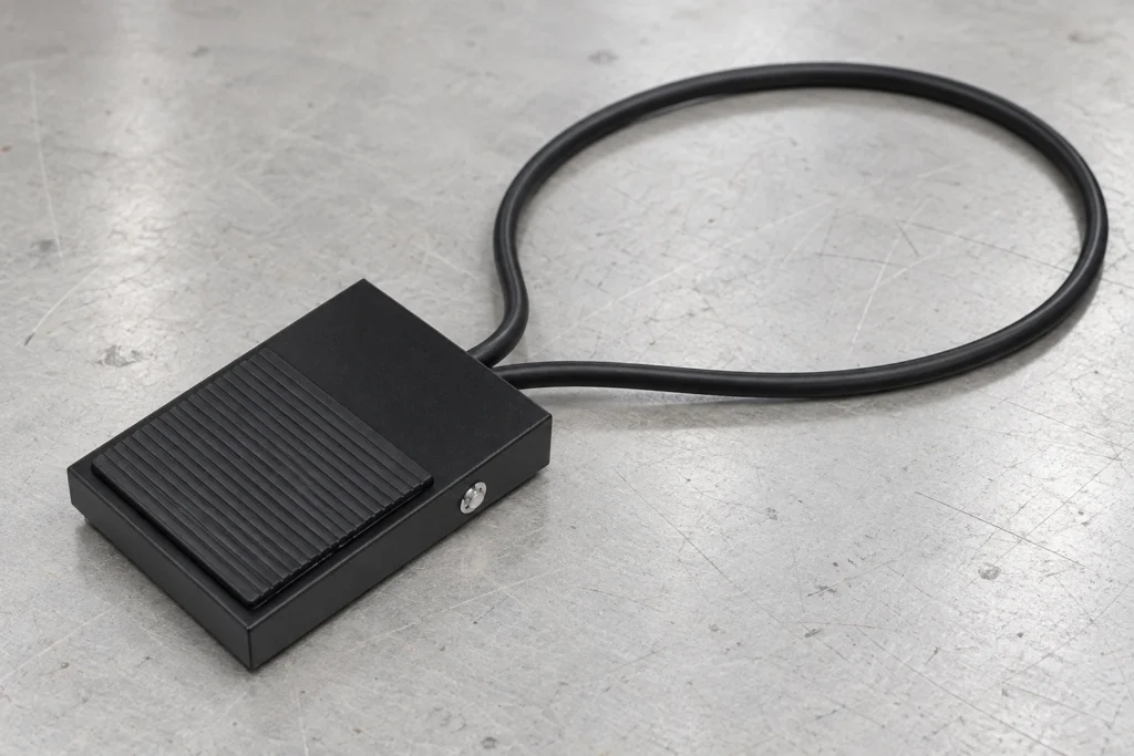
An industrial foot switch should be reviewed as an installed operator interface, not as an isolated pedal. Capture floor conditions, access, mounting, cord routing, circuit context and service clearance before selecting a device. Important: an enclosure appearance or a product label does not prove protection, approval, electrical duty or industrial suitability. Source note: use the selected model documentation and the IEC 60947-5-1 publication scope before release. - FAQ ContentsPart 1. What makes a foot-switch installation industrial?Part 2. Which operator and floor inputs should be documented?Part 3. How should cord routing and circuit context be reviewed?Part 4. Which enclosure and service details matter?Part 5. Why does a general guide not prove model protection?Part 6. What should be validated before release?Part 7. How can LEMA support an inquiry?Part 1. What makes a foot-switch installation industrial? Industrial context is defined by the documented task, floor area, operator access, machine circuit, cable route and maintenance conditions. The product name alone does not describe that assembled interface. Start with the LEMA Foot Switch product line after the installation conditions are recorded. Part 2. Which operator and floor inputs should be documented? Record operator position, access path, footwear, cleaning, debris exposure, surrounding equipment and any space reserved for service. Describe the floor and work cell rather than relying on a generic industrial label. InputDocumentRFQWork cellOperator approach and floor contextYesCircuitControl drawing and required responseYesCord routeExit, protection and replacement accessYes Part 3. How should cord routing and circuit context be reviewed? Review the cable exit, route, strain points, separation from hazards, connection method and replacement path with the circuit drawing. The cord must be evaluated as part of the installed control interface. See the customization input checklist for...

Mehr lesen
Preparing a Custom Foot Switch RFQ for an OEM Build
Blog LEMA Electric

Vorbereitung einer RFQ für einen kundenspezifischen Fußschalter für eine OEM-Montage

A custom foot-switch RFQ starts with the operator task and installed machine context. Document pedal behavior, circuit logic, mounting, cord routing, service access and sample checks before selecting a device. Important: a pedal shape or a catalog image does not prove force, travel, rating, approval, ingress or life. Source note: verify the selected model documentation and the IEC 60947-5-1 publication scope before release. - FAQ ContentsPart 1. What belongs in a custom foot-switch RFQ?Part 2. Which operator and pedal inputs should be captured?Part 3. How should circuit and cord requirements be recorded?Part 4. Which mounting and service inputs matter?Part 5. Why does a general guide not prove model suitability?Part 6. What should be checked on a sample?Part 7. How can LEMA support an inquiry?Part 1. What belongs in a custom foot-switch RFQ? Start with the operator task, machine function, circuit drawing, installation space and service plan. Those inputs make a request reviewable instead of relying on a product name. InputDocumentRFQOperator taskActuation and release expectationYesCircuitControl logic and load contextYesInstallationMounting, cord exit and accessYes Use the manufacturer evaluation context for supplier-review questions. Part 2. Which operator and pedal inputs should be captured? Describe how the operator approaches the pedal, whether footwear or contamination changes access, the expected release behavior and any guarding or placement constraints. Record the installed task rather than a preferred appearance. Part 3. How should circuit and cord requirements be recorded? Supply the control drawing, required circuit state, cable exit direction, routing, strain-relief constraints and replacement access. A cord length or terminal description alone does not define the machine interface. Part 4. Which mounting and service inputs matter? Review floor location, mounting interface, surrounding clearance, cleaning method, cable path...

Mehr lesen
Planning an Illuminated Push Button Switch for an OEM Panel
Blog LEMA Electric

Planung eines beleuchteten Drucktastenschalters für ein OEM-Bedienfeld

An illuminated push button should communicate a documented state within an OEM panel. Define the indicator purpose, circuit logic, panel legend, installation and service process before selecting a device. Important: an illuminated cap, a color or a front-panel photo does not prove lamp voltage, rating, IP class, approval or life. Source note: use selected-model documentation and the IEC 60947-5-1 publication scope before release. - FAQ ContentsPart 1. What is an illuminated push button switch used for?Part 2. Which indicator and circuit inputs should be documented?Part 3. How do contact logic and panel legend work together?Part 4. Which panel and service details matter?Part 5. Why does a general guide not prove model performance?Part 6. What should be validated before release?Part 7. How can LEMA support an inquiry?Part 1. What is an illuminated push button switch used for? It combines an operator control with a visible indication only when the selected device and circuit design document that behavior. Start by describing the state the indicator must communicate to the operator. Use the LEMA Push Button Switch product line after the application file is defined. Part 2. Which indicator and circuit inputs should be documented? Record the intended indication, supply and circuit context, legend, viewing conditions, operator distance, installation orientation and service expectation. Include whether the requirement is a new build, retrofit or sample review. InputDocumentRFQIndicationState to be communicated and legendYesCircuitControl logic and interface drawingYesPanelCutout, thickness and rear accessYes Part 3. How do contact logic and panel legend work together? The legend tells the operator how a documented control is intended to be used; the circuit drawing defines what the control does. Keep both in the same review package so label, behavior and...

Mehr lesen
Planning an Emergency Stop Push Button for an OEM Panel
Blog LEMA Electric

Planung eines Not-Halt-Drucktasters für ein OEM-Schaltpult

An emergency-stop push button inquiry begins with the complete machine function, not button appearance. Record reset method, contact logic, circuit context, panel installation and validation inputs before selecting a device. Important: a red mushroom head or a product label does not prove safety category, approval, rating or machine-function suitability. Source note: use the selected device documentation and the IEC 60947-5-5 publication scope with the machine validation file. - FAQ ContentsPart 1. What is an emergency stop push button for?Part 2. Which reset and operator inputs should be documented?Part 3. How should contact logic and the machine circuit be recorded?Part 4. Which panel-integration details matter?Part 5. Why does a general guide not prove safety-function suitability?Part 6. What should be validated before release?Part 7. How can LEMA support an inquiry?Part 1. What is an emergency stop push button for? It gives an operator a clearly identified input within a documented machine control or safety-function design. The required outcome, reset behavior and system response must be defined before a part is selected. Start from the LEMA Push Button Switch product line once those inputs exist. Part 2. Which reset and operator inputs should be documented? Document the intended reset method, access conditions, operator instructions, location, guarding and service process. State whether the control is used for a new build, replacement or sample evaluation. InputDocumentRFQResetRequired reset behavior and accessYesCircuitControl logic and required responseYesPanelCutout, thickness and rear clearanceYes Part 3. How should contact logic and the machine circuit be recorded? Provide the controlled circuit drawing, contact requirement, load context, wiring method and interface to the machine control design. A contact description alone does not define the complete machine response. Part 4. Which panel-integration details matter?...

Mehr lesen
Planning Marine Exposure Inputs for a Toggle Switch
Blog LEMA Electric

Planung von Meeresexpositionseingaben für einen Kippschalter

Marine toggle selection begins with the actual exposure, not the word “marine.” Capture salt, splash, cleaning, vibration, panel materials, service interval and model evidence before approving a switch for a vessel or coastal system. Important: material, color or a waterproof label does not prove marine certification, corrosion resistance, IP class, rating or life. Source note: marine exposure requires selected-model evidence; the IEC 61058-1 reference is only a standards-scope note. - FAQ ContentsPart 1. What makes a toggle inquiry marine?Part 2. Which salt, splash and maintenance inputs belong in the RFQ?Part 3. How should material and panel interfaces be reviewed?Part 4. Which sealing and service checks matter?Part 5. Why must marine exposure stay separate from electrical rating?Part 6. What should be validated before approval?Part 7. How can LEMA support a marine-toggle inquiry?Part 1. What makes a toggle inquiry marine? Marine context may include salt air, spray, washdown, condensation, vibration, limited service access and changing temperature. Put those conditions in the RFQ instead of relying on a product adjective. InputDocumentRFQExposureSalt, splash, cleaning and orientationYesPanelMaterial, coating and drainageYesServiceInspection and replacement intervalYes Start at the LEMA Toggle Switch product line after inputs are defined. Part 2. Which salt, splash and maintenance inputs belong in the RFQ? State whether the panel is inside, exposed, near spray, or subject to a defined washdown method. Include cleaning chemistry, service intervals, vibration context and any condensation risk. Those inputs determine what evidence must be requested. The IP67 sealing guide is a related process, not a universal marine claim. Part 3. How should material and panel interfaces be reviewed? Review panel material, coating, hardware, labels, bushing interface and drainage. A metal housing or stainless-looking finish does not by itself...

Mehr lesen