LEMA NEWS CENTER

News & Blog

News Center

Cam Limit Switch Working Principle, Setup and Selection Guide
Blog LEMA Electric

Cam Limit Switch Working Principle, Setup and Selection Guide

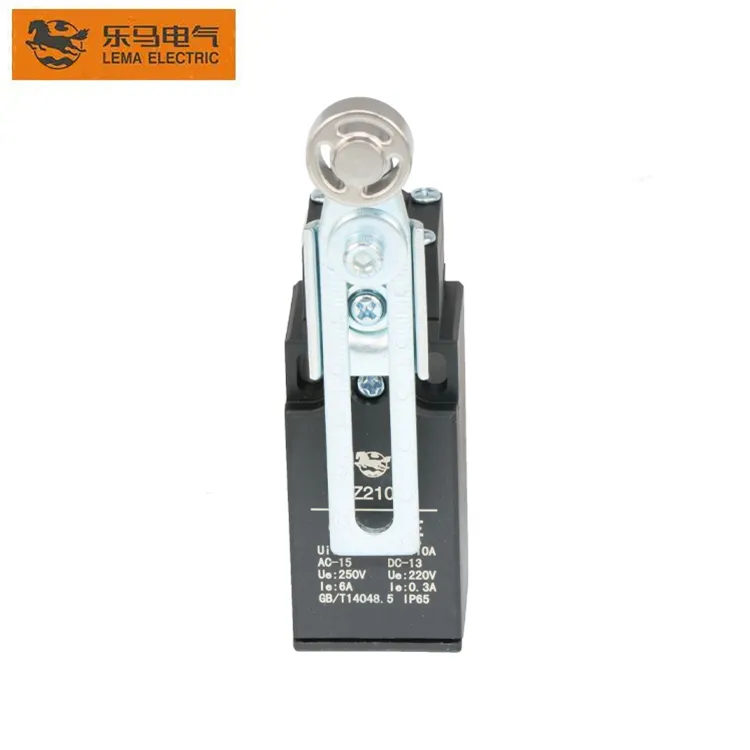
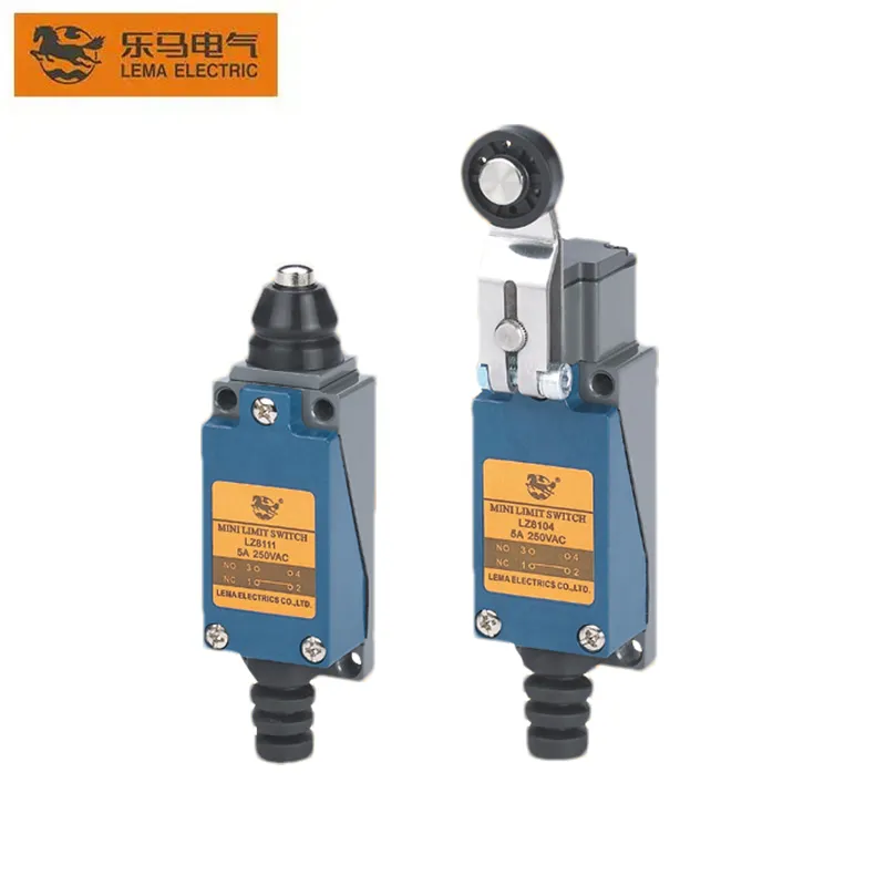
cam limit switch working principle became a priority because Google Search Console already shows real impressions for this topic on LEMA. That signal indicates an existing audience, but the previous site coverage did not fully match the question. This guide turns the query into a practical selection, integration and purchasing workflow for equipment designers, panel builders, maintenance teams and industrial buyers. A cam limit switch converts the angular position of a shaft or machine cycle into one or more electrical state changes. A rotating cam profile reaches an actuator at a chosen angle; the internal snap-action contact then changes state. The useful result is not simply “the cam touched the switch.” It is a repeatable switching window with adequate approach, overtravel and release margin. Setup therefore begins with the machine sequence: identify the earliest and latest acceptable switching angles, account for backlash and stopping distance, and make adjustments at reduced speed. Never use the switch body as the mechanical end stop. Application view showing practical integration points for cam limit switch working principle. What cam limit switch working principle means in a real design A useful specification begins with behavior, not a catalogue photo. Write down what moves, what the operator or machine is trying to achieve, when the electrical state must change, and what should happen if a conductor opens or the device fails to reset. Separate the field device from the controller logic: a switch reports or commands a state, while the relay, PLC or control circuit decides how the machine responds. Similar product families often contain several contact arrangements, actuator styles, terminal forms and mounting versions. The family name helps discovery but does not define a production...

Read More
Electric Foot Switch Selection Guide for Industrial Equipment
Blog LEMA Electric

Electric Foot Switch Selection Guide for Industrial Equipment

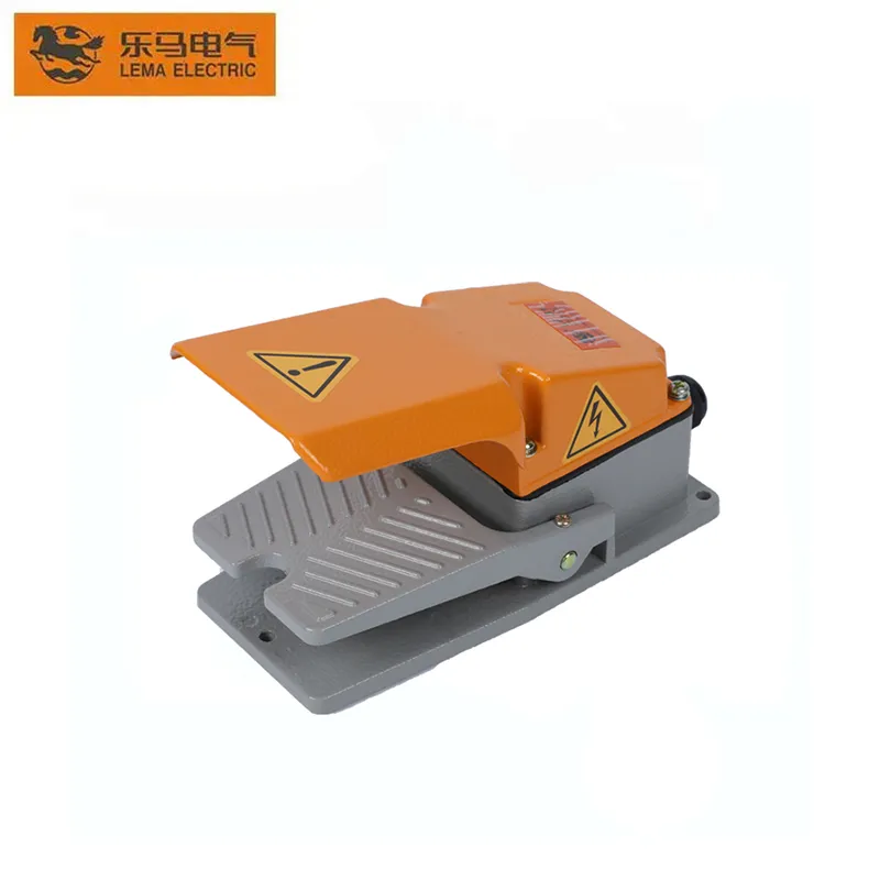
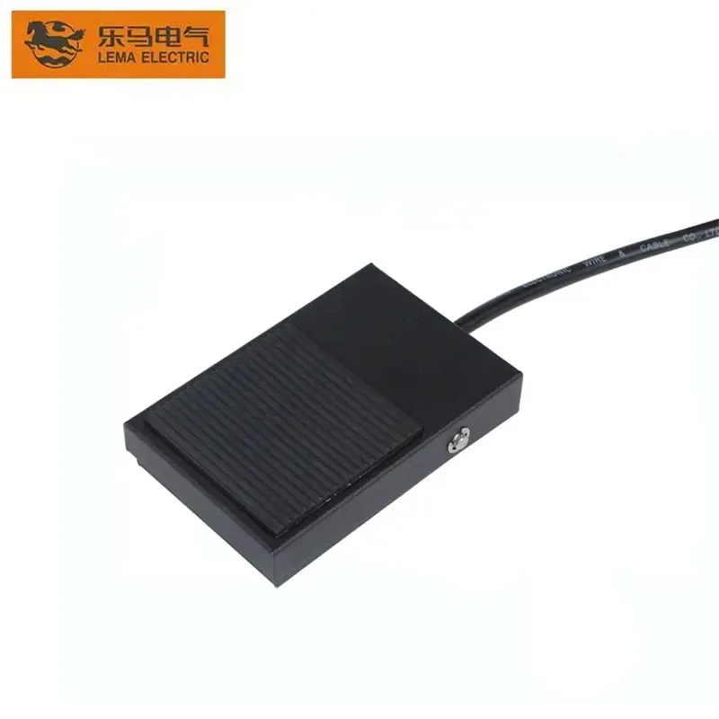
electric foot switch became a priority because Google Search Console already shows real impressions for this topic on LEMA. That signal indicates an existing audience, but the previous site coverage did not fully match the question. This guide turns the query into a practical selection, integration and purchasing workflow for equipment designers, panel builders, maintenance teams and industrial buyers. An electric foot switch gives an operator hands-free control, but it is not automatically a safeguarding device. Start by deciding whether the pedal sends a momentary start signal, maintains a circuit, jogs motion, or enables another control. Then document the normal and actuated contact states. A protected hood can reduce unintended access, while pedal shape, force, travel and floor stability determine whether the operator can use it repeatedly without awkward posture. For punching and similar machinery, the pedal must be evaluated as part of the complete control and guarding system. Do not rely on a foot control to keep hands away from a hazardous point of operation. Application view showing practical integration points for electric foot switch. What electric foot switch means in a real design A useful specification begins with behavior, not a catalogue photo. Write down what moves, what the operator or machine is trying to achieve, when the electrical state must change, and what should happen if a conductor opens or the device fails to reset. Separate the field device from the controller logic: a switch reports or commands a state, while the relay, PLC or control circuit decides how the machine responds. Similar product families often contain several contact arrangements, actuator styles, terminal forms and mounting versions. The family name helps discovery but does not define a...

Read More
12-Volt Power Socket Selection, Wiring and Protection Guide
Blog LEMA Electric

12-Volt Power Socket Selection, Wiring and Protection Guide

12 volt power socket selection starts by defining the required machine or equipment function, then matching the electrical interface, mechanical mounting and environment to one exact component. This guide explains matching connector format, current demand, conductors, polarity, overcurrent protection, panel mounting and environmental exposure. “12 volt” is a nominal system label rather than a complete rating. Actual voltage range, current, duty cycle, polarity, connector geometry, conductor size and protective device coordination must be defined separately. Treat every terminal diagram, rating and dimension as model-specific, and validate the assembled system before production use. What the term means in an equipment design“12 volt” is a nominal system label rather than a complete rating. Actual voltage range, current, duty cycle, polarity, connector geometry, conductor size and protective device coordination must be defined separately. This distinction matters because search results often mix replacement parts, hobby wiring examples, complete control assemblies and bare industrial components. An OEM design needs a controlled specification rather than a visual match. Record the intended function in plain language, the normal and actuated states, the equipment supply, the connected load or controller input, and the consequence of a disconnected wire.The component should be considered together with its mating part, mounting structure, conductors, enclosure and controller logic. A correct component installed in an unsuitable cutout or connected to an incompatible load is still an incorrect system. When a seller offers several variants under one family name, request the variant drawing and do not transfer ratings or terminal positions from a neighboring model. Panel power socket used to review terminals and mounting. Verify the exact model drawing before production use. Selection decisions that prevent redesignDesign inputSelection questionVerificationNominal systemWhat voltage range exists during...

Read More
Limit Switch Accessories Selection and Integration Guide
Blog LEMA Electric

Limit Switch Accessories Selection and Integration Guide

limit switch accessories selection starts by defining the required machine or equipment function, then matching the electrical interface, mechanical mounting and environment to one exact component. This guide explains selecting levers, rollers, rods, brackets, glands, connectors and target cams while preserving mechanical and electrical compatibility. An accessory is part of the sensing system, not a cosmetic add-on. A lever length, roller diameter, bracket stiffness or cable gland can change operating force, travel, sealing, repeatability and service access. Treat every terminal diagram, rating and dimension as model-specific, and validate the assembled system before production use. What the term means in an equipment designAn accessory is part of the sensing system, not a cosmetic add-on. A lever length, roller diameter, bracket stiffness or cable gland can change operating force, travel, sealing, repeatability and service access. This distinction matters because search results often mix replacement parts, hobby wiring examples, complete control assemblies and bare industrial components. An OEM design needs a controlled specification rather than a visual match. Record the intended function in plain language, the normal and actuated states, the equipment supply, the connected load or controller input, and the consequence of a disconnected wire.The component should be considered together with its mating part, mounting structure, conductors, enclosure and controller logic. A correct component installed in an unsuitable cutout or connected to an incompatible load is still an incorrect system. When a seller offers several variants under one family name, request the variant drawing and do not transfer ratings or terminal positions from a neighboring model. Industrial limit switch and actuator hardware for accessory planning. Verify the exact model drawing before production use. Selection decisions that prevent redesignAccessory groupPurposeCompatibility checkActuator head or...

Read More
Momentary Micro Switch Selection and Actuation Guide
Blog LEMA Electric

Momentary Micro Switch Selection and Actuation Guide

micro switch momentary selection starts by defining the required machine or equipment function, then matching the electrical interface, mechanical mounting and environment to one exact component. This guide explains matching operating and release points to machine travel, choosing an actuator, allowing overtravel, controlling contact logic and testing repeatability. Momentary describes automatic return after force is removed. Snap action describes how the internal contacts change state. The two ideas are related in many micro switches, but they are not interchangeable specifications. Treat every terminal diagram, rating and dimension as model-specific, and validate the assembled system before production use. What the term means in an equipment designMomentary describes automatic return after force is removed. Snap action describes how the internal contacts change state. The two ideas are related in many micro switches, but they are not interchangeable specifications. This distinction matters because search results often mix replacement parts, hobby wiring examples, complete control assemblies and bare industrial components. An OEM design needs a controlled specification rather than a visual match. Record the intended function in plain language, the normal and actuated states, the equipment supply, the connected load or controller input, and the consequence of a disconnected wire.The component should be considered together with its mating part, mounting structure, conductors, enclosure and controller logic. A correct component installed in an unsuitable cutout or connected to an incompatible load is still an incorrect system. When a seller offers several variants under one family name, request the variant drawing and do not transfer ratings or terminal positions from a neighboring model. Momentary micro switch mechanism and actuator area. Verify the exact model drawing before production use. Selection decisions that prevent redesignParameterQuestionFailure avoidedOperating pointWhere must...

Read More
3-Pin Power Socket Symbol and Schematic Reading Guide
Blog LEMA Electric

3-Pin Power Socket Symbol and Schematic Reading Guide

3 pin power socket symbol selection starts by defining the required machine or equipment function, then matching the electrical interface, mechanical mounting and environment to one exact component. This guide explains reading line, neutral and protective-earth indications, separating schematic symbols from physical pin layouts, and cross-checking drawings before wiring. A schematic symbol communicates electrical function. It is not a front-view or rear-view photograph, and it cannot replace the terminal markings and manufacturer drawing for the exact socket. Treat every terminal diagram, rating and dimension as model-specific, and validate the assembled system before production use. What the term means in an equipment designA schematic symbol communicates electrical function. It is not a front-view or rear-view photograph, and it cannot replace the terminal markings and manufacturer drawing for the exact socket. This distinction matters because search results often mix replacement parts, hobby wiring examples, complete control assemblies and bare industrial components. An OEM design needs a controlled specification rather than a visual match. Record the intended function in plain language, the normal and actuated states, the equipment supply, the connected load or controller input, and the consequence of a disconnected wire.The component should be considered together with its mating part, mounting structure, conductors, enclosure and controller logic. A correct component installed in an unsuitable cutout or connected to an incompatible load is still an incorrect system. When a seller offers several variants under one family name, request the variant drawing and do not transfer ratings or terminal positions from a neighboring model. Three-terminal appliance inlet for schematic cross-checking. Verify the exact model drawing before production use. Selection decisions that prevent redesignMarkingTypical design roleDo not assumeL or lineEnergized conductor pathTerminal position without the...

Read More
Sealed Toggle Switch Selection for Dust, Moisture and Panels
Blog LEMA Electric

Sealed Toggle Switch Selection for Dust, Moisture and Panels

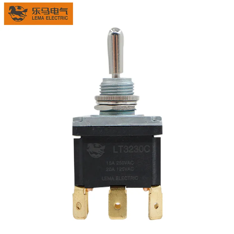
sealed toggle switch selection starts by defining the required machine or equipment function, then matching the electrical interface, mechanical mounting and environment to one exact component. This guide explains defining the real exposure, separating front-of-panel sealing from complete-device protection, selecting boots and gaskets, and validating the assembled panel. A sealed toggle switch does not automatically make an enclosure sealed. Protection depends on the switch construction, panel joint, boot or gasket, rear terminals, mounting quality and every other opening in the enclosure. Treat every terminal diagram, rating and dimension as model-specific, and validate the assembled system before production use. What the term means in an equipment designA sealed toggle switch does not automatically make an enclosure sealed. Protection depends on the switch construction, panel joint, boot or gasket, rear terminals, mounting quality and every other opening in the enclosure. This distinction matters because search results often mix replacement parts, hobby wiring examples, complete control assemblies and bare industrial components. An OEM design needs a controlled specification rather than a visual match. Record the intended function in plain language, the normal and actuated states, the equipment supply, the connected load or controller input, and the consequence of a disconnected wire.The component should be considered together with its mating part, mounting structure, conductors, enclosure and controller logic. A correct component installed in an unsuitable cutout or connected to an incompatible load is still an incorrect system. When a seller offers several variants under one family name, request the variant drawing and do not transfer ratings or terminal positions from a neighboring model. Toggle switch with sealing boot and panel hardware. Verify the exact model drawing before production use. Selection decisions that prevent redesignIngress...

Read More
SPST Micro Switch Selection and Circuit Integration Guide
Blog LEMA Electric

SPST Micro Switch Selection and Circuit Integration Guide

micro switch spst selection starts by defining the required machine or equipment function, then matching the electrical interface, mechanical mounting and environment to one exact component. This guide explains distinguishing SPST-NO from SPST-NC, matching the actuator to the mechanism, checking load conditions, tolerances and life expectations. SPST identifies one pole and one controlled path, but many familiar snap-action micro switches expose COM, NO and NC as an SPDT contact. Confirm the actual terminal diagram instead of choosing from the product silhouette. Treat every terminal diagram, rating and dimension as model-specific, and validate the assembled system before production use. What the term means in an equipment designSPST identifies one pole and one controlled path, but many familiar snap-action micro switches expose COM, NO and NC as an SPDT contact. Confirm the actual terminal diagram instead of choosing from the product silhouette. This distinction matters because search results often mix replacement parts, hobby wiring examples, complete control assemblies and bare industrial components. An OEM design needs a controlled specification rather than a visual match. Record the intended function in plain language, the normal and actuated states, the equipment supply, the connected load or controller input, and the consequence of a disconnected wire.The component should be considered together with its mating part, mounting structure, conductors, enclosure and controller logic. A correct component installed in an unsuitable cutout or connected to an incompatible load is still an incorrect system. When a seller offers several variants under one family name, request the variant drawing and do not transfer ratings or terminal positions from a neighboring model. Compact micro switch body for contact and actuator review. Verify the exact model drawing before production use. Selection decisions...

Read More
Power Socket Panel Mount Installation and Selection Guide
Blog LEMA Electric

Power Socket Panel Mount Installation and Selection Guide

power socket panel mount selection starts by defining the required machine or equipment function, then matching the electrical interface, mechanical mounting and environment to one exact component. This guide explains translating a socket drawing into a correct panel cutout, selecting retention style, managing rear clearance and inspecting the finished installation. Panel mount is a mechanical description rather than a connector standard. Two sockets that look similar from the front can require different cutouts, panel thicknesses, terminal clearances and mating connectors. Treat every terminal diagram, rating and dimension as model-specific, and validate the assembled system before production use. What the term means in an equipment designPanel mount is a mechanical description rather than a connector standard. Two sockets that look similar from the front can require different cutouts, panel thicknesses, terminal clearances and mating connectors. This distinction matters because search results often mix replacement parts, hobby wiring examples, complete control assemblies and bare industrial components. An OEM design needs a controlled specification rather than a visual match. Record the intended function in plain language, the normal and actuated states, the equipment supply, the connected load or controller input, and the consequence of a disconnected wire.The component should be considered together with its mating part, mounting structure, conductors, enclosure and controller logic. A correct component installed in an unsuitable cutout or connected to an incompatible load is still an incorrect system. When a seller offers several variants under one family name, request the variant drawing and do not transfer ratings or terminal positions from a neighboring model. Panel-mounted power inlet viewed from the equipment exterior. Verify the exact model drawing before production use. Selection decisions that prevent redesignMounting issueDrawing checkInstallation checkCutoutNominal size,...

Read More
Momentary Foot Switch Selection Guide for Industrial Controls
Blog LEMA Electric

Momentary Foot Switch Selection Guide for Industrial Controls

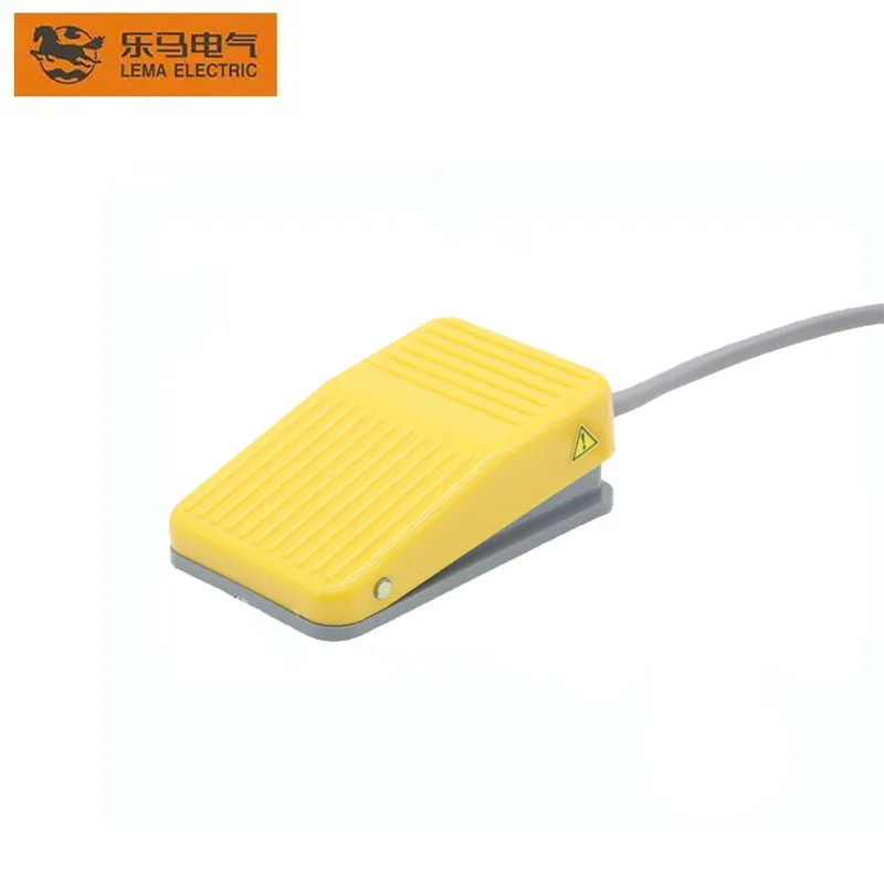
momentary foot switch selection starts by defining the required machine or equipment function, then matching the electrical interface, mechanical mounting and environment to one exact component. This guide explains choosing momentary action, guarding, contact logic, pedal force, cable arrangement and commissioning checks for hands-free control. Momentary action describes how the contact returns after the operator releases the pedal. It does not by itself define safe-stop behavior, electrical rating, enclosure protection or whether the machine may use the pedal as a cycle-start device. Treat every terminal diagram, rating and dimension as model-specific, and validate the assembled system before production use. What the term means in an equipment designMomentary action describes how the contact returns after the operator releases the pedal. It does not by itself define safe-stop behavior, electrical rating, enclosure protection or whether the machine may use the pedal as a cycle-start device. This distinction matters because search results often mix replacement parts, hobby wiring examples, complete control assemblies and bare industrial components. An OEM design needs a controlled specification rather than a visual match. Record the intended function in plain language, the normal and actuated states, the equipment supply, the connected load or controller input, and the consequence of a disconnected wire.The component should be considered together with its mating part, mounting structure, conductors, enclosure and controller logic. A correct component installed in an unsuitable cutout or connected to an incompatible load is still an incorrect system. When a seller offers several variants under one family name, request the variant drawing and do not transfer ratings or terminal positions from a neighboring model. Momentary foot switch body and guarded pedal area. Verify the exact model drawing before production use....

Read More
C14 Power Socket Selection Guide for Equipment Panels
Blog LEMA Electric

C14 Power Socket Selection Guide for Equipment Panels

c14 power socket selection starts by defining the required machine or equipment function, then matching the electrical interface, mechanical mounting and environment to one exact component. This guide explains identifying the C14 interface, selecting panel retention and terminals, coordinating the mating cord, and verifying the complete equipment inlet assembly. C14 describes the appliance inlet interface, not the entire power-entry system. The cord, mating connector, fuse, switch, filter, wiring and protective earth arrangement remain separate design decisions. Treat every terminal diagram, rating and dimension as model-specific, and validate the assembled system before production use. What the term means in an equipment designC14 describes the appliance inlet interface, not the entire power-entry system. The cord, mating connector, fuse, switch, filter, wiring and protective earth arrangement remain separate design decisions. This distinction matters because search results often mix replacement parts, hobby wiring examples, complete control assemblies and bare industrial components. An OEM design needs a controlled specification rather than a visual match. Record the intended function in plain language, the normal and actuated states, the equipment supply, the connected load or controller input, and the consequence of a disconnected wire.The component should be considered together with its mating part, mounting structure, conductors, enclosure and controller logic. A correct component installed in an unsuitable cutout or connected to an incompatible load is still an incorrect system. When a seller offers several variants under one family name, request the variant drawing and do not transfer ratings or terminal positions from a neighboring model. Rear terminal side of an AC appliance inlet for panel integration. Verify the exact model drawing before production use. Selection decisions that prevent redesignSelection pointQuestion for the drawing or supplierEngineering consequenceMating interfaceIs...

Read More
Foot Pedal Foot Switch Wiring Diagram: Terminals and Connection Checks
Blog LEMA Electric

Foot Pedal Foot Switch Wiring Diagram: Terminals and Connection Checks

foot pedal foot switch wiring diagram selection starts by defining the required machine or equipment function, then matching the electrical interface, mechanical mounting and environment to one exact component. This guide explains how to identify terminals, choose NO or NC behavior, route the cable, test continuity and commission the machine input safely. A foot pedal is only the field input. The control circuit, relay, PLC or machine controller determines what the pedal actually starts, stops or enables. Treat every terminal diagram, rating and dimension as model-specific, and validate the assembled system before production use. What the term means in an equipment designA foot pedal is only the field input. The control circuit, relay, PLC or machine controller determines what the pedal actually starts, stops or enables. This distinction matters because search results often mix replacement parts, hobby wiring examples, complete control assemblies and bare industrial components. An OEM design needs a controlled specification rather than a visual match. Record the intended function in plain language, the normal and actuated states, the equipment supply, the connected load or controller input, and the consequence of a disconnected wire.The component should be considered together with its mating part, mounting structure, conductors, enclosure and controller logic. A correct component installed in an unsuitable cutout or connected to an incompatible load is still an incorrect system. When a seller offers several variants under one family name, request the variant drawing and do not transfer ratings or terminal positions from a neighboring model. Industrial foot switch housing and cable entry for wiring inspection. Verify the exact model drawing before production use. Selection decisions that prevent redesignCheckWhat to verifyWhy it mattersContact logicCOM, NO and NC identified from...

Read More