LEMA NEWS CENTER

News & Blog

News Center

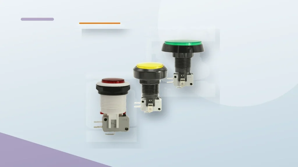
Planning an Emergency Stop Push Button for an OEM Panel
Blog LEMA Electric

Planning an Emergency Stop Push Button for an OEM Panel

An emergency-stop push button inquiry begins with the complete machine function, not button appearance. Record reset method, contact logic, circuit context, panel installation and validation inputs before selecting a device. Important: a red mushroom head or a product label does not prove safety category, approval, rating or machine-function suitability. Source note: use the selected device documentation and the IEC 60947-5-5 publication scope with the machine validation file. - FAQ ContentsPart 1. What is an emergency stop push button for?Part 2. Which reset and operator inputs should be documented?Part 3. How should contact logic and the machine circuit be recorded?Part 4. Which panel-integration details matter?Part 5. Why does a general guide not prove safety-function suitability?Part 6. What should be validated before release?Part 7. How can LEMA support an inquiry?Part 1. What is an emergency stop push button for? It gives an operator a clearly identified input within a documented machine control or safety-function design. The required outcome, reset behavior and system response must be defined before a part is selected. Start from the LEMA Push Button Switch product line once those inputs exist. Part 2. Which reset and operator inputs should be documented? Document the intended reset method, access conditions, operator instructions, location, guarding and service process. State whether the control is used for a new build, replacement or sample evaluation. InputDocumentRFQResetRequired reset behavior and accessYesCircuitControl logic and required responseYesPanelCutout, thickness and rear clearanceYes Part 3. How should contact logic and the machine circuit be recorded? Provide the controlled circuit drawing, contact requirement, load context, wiring method and interface to the machine control design. A contact description alone does not define the complete machine response. Part 4. Which panel-integration details matter?...

Read More
Planning Marine Exposure Inputs for a Toggle Switch
Blog LEMA Electric

Planning Marine Exposure Inputs for a Toggle Switch

Marine toggle selection begins with the actual exposure, not the word “marine.” Capture salt, splash, cleaning, vibration, panel materials, service interval and model evidence before approving a switch for a vessel or coastal system. Important: material, color or a waterproof label does not prove marine certification, corrosion resistance, IP class, rating or life. Source note: marine exposure requires selected-model evidence; the IEC 61058-1 reference is only a standards-scope note. - FAQ ContentsPart 1. What makes a toggle inquiry marine?Part 2. Which salt, splash and maintenance inputs belong in the RFQ?Part 3. How should material and panel interfaces be reviewed?Part 4. Which sealing and service checks matter?Part 5. Why must marine exposure stay separate from electrical rating?Part 6. What should be validated before approval?Part 7. How can LEMA support a marine-toggle inquiry?Part 1. What makes a toggle inquiry marine? Marine context may include salt air, spray, washdown, condensation, vibration, limited service access and changing temperature. Put those conditions in the RFQ instead of relying on a product adjective. InputDocumentRFQExposureSalt, splash, cleaning and orientationYesPanelMaterial, coating and drainageYesServiceInspection and replacement intervalYes Start at the LEMA Toggle Switch product line after inputs are defined. Part 2. Which salt, splash and maintenance inputs belong in the RFQ? State whether the panel is inside, exposed, near spray, or subject to a defined washdown method. Include cleaning chemistry, service intervals, vibration context and any condensation risk. Those inputs determine what evidence must be requested. The IP67 sealing guide is a related process, not a universal marine claim. Part 3. How should material and panel interfaces be reviewed? Review panel material, coating, hardware, labels, bushing interface and drainage. A metal housing or stainless-looking finish does not by itself...

Read More
Where Toggle Switches Fit in OEM Control Panels
Blog LEMA Electric

Where Toggle Switches Fit in OEM Control Panels

A toggle switch gives an operator a physical way to select a documented circuit state. OEM selection still depends on poles, throws, load, environment, mounting and service access. Important: a general use-case explanation does not prove any model rating, sealing, approval or life. Source note: use the selected model datasheet to confirm the control-panel boundary; IEC 61058-1 is scope context. - FAQ ContentsPart 1. What is a toggle switch used for?Part 2. Which circuit states can it control?Part 3. Which OEM applications commonly use toggles?Part 4. How do panel and environment inputs change selection?Part 5. What are the limits of a general use-case answer?Part 6. What should be validated before release?Part 7. How can LEMA support an inquiry?Part 1. What is a toggle switch used for? It is used when an operator needs a clear, physical selection between documented states such as enable/disable, source selection, mode selection or a maintained control position. Part 2. Which circuit states can it control? ON-OFF, ON-OFF-ON, SPDT and DPDT arrangements express different state and pole requirements. The schematic, not the lever appearance, defines the intended behavior. InputDocumentRFQStateMaintained or momentary positionYesPolesIndependent circuitsYesDutyVoltage, load and inrushYes See the state-logic guide. Part 3. Which OEM applications commonly use toggles? Common examples include equipment mode selection, operator panels, appliance controls, vehicle modules and industrial interfaces. Each application still requires its own duty and environment review. The automotive dashboard guide shows why panel context matters. Part 4. How do panel and environment inputs change selection? Cutout, panel thickness, rear clearance, labels, guards, splash, dust and service access all change the selection. A toggle used indoors on a dry panel is a different review from one exposed to washdown or...

Read More
Planning a Quick Connect Toggle Switch Harness for OEM Assembly
Blog LEMA Electric

Planning a Quick Connect Toggle Switch Harness for OEM Assembly

A quick-connect toggle succeeds when the terminal interface and harness process are controlled together. Define the mating component, terminal map, routing, access, inspection and service steps before a buyer releases a production panel. Important: do not infer terminal size, retention, electrical rating, ingress, approval or life from a terminal photo. Confirm model-specific limits in the selected documentation. Source note: IEC 61058-1 publication scope and selected-model documentation. - FAQ ContentsPart 1. What does quick connect mean in an OEM toggle design?Part 2. Which terminal and harness inputs belong in the drawing?Part 3. How should mating access and retention be reviewed?Part 4. Which assembly and inspection controls reduce rework?Part 5. How should service and terminal changes be controlled?Part 6. What should be validated before release?Part 7. How can LEMA support a quick-connect inquiry?Part 1. What does quick connect mean in an OEM toggle design? Quick connect describes a mating approach, not a complete harness specification. The design file still needs the terminal drawing, matching component, wire route, tool access, inspection method and the intended service sequence. Without those fields, similar-looking terminals can create unplanned substitutions or rework. Decision fieldRecord in the packageSend with quoteTerminal mapContact and terminal designation on the drawingYesMating interfaceMatching component and harness processYesAccessRear clearance and service approachYesDutyLoad, inrush and circuit contextYes Begin at the LEMA Toggle Switch product line after the application package is defined. Part 2. Which terminal and harness inputs belong in the drawing? Show each terminal designation with the matching harness connection and circuit state. Identify the wire construction, routing, strain-relief decision and any assembly instruction needed to keep a mating connection consistent. Do not use a generic “quick connect” label in place of the released...

Read More
Planning a Rubber Toggle Switch Cover for an OEM Panel
Blog LEMA Electric

Planning a Rubber Toggle Switch Cover for an OEM Panel

A rubber cover is part of the panel assembly, not an independent waterproof promise. Review the cover, lever, bushing, front panel and service procedure together before releasing an OEM enclosure design. Important: do not infer IP class, material compatibility, electrical rating, approval or service life from a cover photo. Confirm model-specific boundaries in the selected documentation. Source note: IEC 61058-1 publication scope and selected-model documentation. - FAQ ContentsPart 1. What does a rubber cover change in a toggle panel?Part 2. Which lever and panel dimensions belong in the RFQ?Part 3. How should exposure be described without unsupported IP claims?Part 4. Which installation and service-access checks matter?Part 5. Why must cover selection remain separate from electrical duty?Part 6. What should be validated on the assembled panel?Part 7. How can LEMA support a rubber-cover inquiry?Part 1. What does a rubber cover change in a toggle panel? The cover adds another interface between the operator and the panel. Its opening, lever travel, bushing location, retention approach and surrounding panel surface all affect the finished assembly. Treat those items as an engineered envelope rather than an accessory purchased after the switch is selected. Decision fieldRecord in the packageSend with quoteGeometryLever, bushing, cover opening and panel stackYesExposureSplash, cleaning, dust and service contextYesOperationTravel, glove use and accidental-actuation concernsYesServiceRemoval path, replacement and inspection accessYes Use the LEMA Toggle Switch product line as a public starting point once the enclosure inputs are known. Part 2. Which lever and panel dimensions belong in the RFQ? Capture the selected lever envelope, bushing drawing, panel thickness, coating stack, cover opening, front clearance and rear access. The supplier needs the assembled dimensions, not just a request for a “standard boot.” Include how...

Read More
Verifying 15A 250V Toggle Switch Duty Before OEM Release
Blog LEMA Electric

Verifying 15A 250V Toggle Switch Duty Before OEM Release

A 15A 250V label is a selection input, not a complete application decision. Put the actual voltage, load type, inrush, operation rate, terminal process and mounting context into the duty file before an OEM approves a sample. Important: do not transfer a headline rating, ingress result, approval or life claim from another product to a LEMA model. Selected-model documentation controls the final boundary. Source note: IEC 61058-1 publication scope and selected-model documentation. - FAQ ContentsPart 1. What does a 15A 250V label establish—and what does it not?Part 2. Which voltage and load inputs belong in the RFQ?Part 3. Why do inrush and operation rate change the review?Part 4. Which terminal and mounting checks belong beside the duty file?Part 5. How should model documentation control the final decision?Part 6. What should be validated before OEM release?Part 7. How can LEMA support a duty-verification inquiry?Part 1. What does a 15A 250V label establish—and what does it not? The label identifies a stated rating context that must be read with the product documentation. It does not tell an OEM whether the actual load is resistive, inductive, lamp-related or otherwise subject to different make and break conditions. Start the review with the real duty, then compare it with the selected-model documents. Decision fieldRecord in the packageSend with quoteSupplyVoltage class and circuit arrangementYesLoadResistive, inductive, lamp or other documented typeYesEventsInrush, operation rate and abnormal statesYesBuildTerminals, cutout, enclosure and accessYes Use the LEMA Toggle Switch product line only after the duty inputs are defined. Part 2. Which voltage and load inputs belong in the RFQ? State nominal supply, acceptable variation, circuit form, load type, steady current and switching purpose. The review should also identify whether the circuit...

Read More
Integrating an Illuminated Toggle Switch Into an OEM Panel
Blog LEMA Electric

Integrating an Illuminated Toggle Switch Into an OEM Panel

An illuminated toggle adds a second communication circuit to the panel. Decide what the indicator means, where it is sourced, and how service verifies it before the design team releases the harness. Important: an illuminated appearance does not establish a lamp or LED voltage, current rating, ingress result, approval or life. Confirm every model-specific limit in the selected documentation. Source note: IEC 61058-1 publication scope and selected-model documentation. - FAQ ContentsPart 1. What does illumination add to a toggle circuit?Part 2. Which source and state inputs belong on the drawing?Part 3. How should indicator terminals and harness routing be controlled?Part 4. How do panel legends and service visibility affect the design?Part 5. Why must the indicator remain separate from load assumptions?Part 6. What should be validated before sample approval?Part 7. How can LEMA support an illuminated-toggle inquiry?Part 1. What does illumination add to a toggle circuit? The indicator communicates a chosen condition to an operator; the switch contacts control a circuit. Those conditions may align, but they must never be assumed to be identical. Capture whether the legend should show source availability, a selected state, an active load, or a fault-related condition, then build the drawing around that decision. Decision fieldRecord in the packageSend with quoteMeaningWhat the panel indication representsYesSourceWhere the indicator circuit is fedYesStateWhich circuit state is intended to be visibleYesServiceLegend, test point and replacement pathYes Begin product-family navigation at the LEMA Toggle Switch product line after those inputs are written. Part 2. Which source and state inputs belong on the drawing? Show the main load path and the indicator path separately. A source-powered indicator can communicate panel availability while a load-following indicator can communicate a switched condition; the...

Read More
How OEM buyers can consolidate wholesale toggle-switch requirements
Blog LEMA Electric

How OEM buyers can consolidate wholesale toggle-switch requirements

When an OEM uses several toggle-switch descriptions across panels, harnesses or equipment variants, “wholesale” can sound like a simple volume-buying task. It is not. A lower number of purchase lines is useful only when the function, interface and approval record remain under control. The practical goal is to make each request comparable before asking for a quote. That protects purchasing from comparing unlike options and gives engineering a clear point at which an alternative needs review rather than an informal “same as” decision. Consolidation is an approval decision, not a SKU-count target Start by separating two ideas that are often combined: Buying fewer lines may simplify purchasing and inventory. Approving fewer configurations changes the engineering and quality boundary. Those actions can happen together, but they do not automatically mean the same thing. Two switches may look alike in a catalogue and still need different circuit functions, lever positions, terminals, panel interfaces or environmental provisions. Until the responsible team accepts that boundary, keep the parts as separate lines. For product-family exploration, use the LEMA Toggle Switch category to locate its current LT1, LT2, LT3 and waterproof paths. Treat the category as a starting point for an exact-model review—not as proof that any two listed products are interchangeable. Build a controlled line-item record before requesting a wholesale quote An RFQ becomes comparable when the buyer supplies the information that must not drift during quotation or re-ordering. The following record is deliberately evidence-led: it asks for requirements and documents, rather than guessing from a photo or a broad product title. Field to lock What the buyer records What the supplier should return or confirm Why it matters for consolidation Function Required circuit behaviour...

Read More
Maintained vs. Momentary Toggle Switch: Choose by Release Behavior
Blog LEMA Electric

Maintained vs. Momentary Toggle Switch: Choose by Release Behavior

A maintained toggle switch stays in its selected state after the lever is released. A momentary toggle switch is active only while the lever is being held and then returns to its rest position. That release behavior—not the word “toggle”—is the first decision for an OEM panel or equipment control. For a control that must remain ON, OFF, or in its selected route after the operator lets go, start with maintained action. For a control intended to act only during a hold, start with momentary action and verify the exact return positions in the selected part’s drawing. TE Connectivity’s toggle-switch overview makes the same core distinction: both maintained-contact and momentary toggle types exist. The practical difference for a panel specification Question Maintained action Momentary action What happens when the operator releases the lever? The selected state remains until the switch is actuated again. The active state ends when the lever is released and the mechanism returns to its stated rest position. Best first-use question “Should this circuit state persist without the operator holding the lever?” “Should this command exist only while the operator holds the lever?” What must be confirmed in the part documentation? The available positions and the circuit state associated with each position. Which position or positions spring back, and the complete return map. Common purchasing risk Buying a general “toggle” without confirming the state that remains after release. Treating a generic ON/OFF label or a center position as proof of spring return. The terms vary across catalogues. Some use “latching” or “alternate” for a state that remains after actuation; Panasonic’s explanation of momentary and alternate operation illustrates the distinction. Treat those words as prompts to read the...

Read More
Selecting a Metal Toggle Switch for the Panel Environment
Blog LEMA Electric

Selecting a Metal Toggle Switch for the Panel Environment

Metal housing is an input to review, not proof that a toggle is ready for every environment. Define the panel material, finish expectation, exposure, rear access and terminal process before a buyer treats a metal toggle as a final selection. Important: do not infer corrosion, ingress, current rating, approval or life performance from housing appearance. Confirm those boundaries with selected-model documentation. Source note: IEC 61058-1 publication scope and selected-model documentation. - FAQs ContentsPart 1. What does metal housing change in a toggle selection?Part 2. Which finish and panel inputs should an OEM document?Part 3. How should exposure be separated from unsupported sealing claims?Part 4. Which mounting and service-access checks matter?Part 5. Why must terminal and load review stay separate?Part 6. What should be validated before sample approval?Part 7. How can LEMA support a metal-toggle inquiry?Part 1. What does metal housing change in a toggle selection? A metal housing changes the interface discussion: panel contact, finish compatibility, bushing retention, grounding considerations where applicable, and service access. It does not collapse the electrical, environmental and approval checks into one material decision. Treat the housing as one field in a controlled selection file. Decision fieldRecord in the packageSend with quotePanelMaterial, thickness, coating and cutoutYesExposureIndoor/outdoor, cleaning, contamination and temperature contextYesMountingHardware stack, clearance and service accessYesElectricalLoad, terminal process and circuit formYes Use the LEMA Toggle Switch product line as a navigation starting point after the selection file is complete. Part 2. Which finish and panel inputs should an OEM document? Specify the actual panel material and coating stack, not just a color. A plated, painted or stainless front has different assembly and service questions from an uncoated steel panel. Document any cosmetic zone, marking requirement,...

Read More
Planning an OEM Harness Around a Screw Terminal Toggle Switch
Blog LEMA Electric

Planning an OEM Harness Around a Screw Terminal Toggle Switch

A screw-terminal toggle is only as reliable as the drawing and process around it. Put the conductor, termination style, rear access, inspection method and service label into one controlled package before a buyer approves samples. Important: a familiar screw head does not establish torque, current capacity, environmental suitability or approval. Those limits must come from the selected-model documentation. Source note: IEC 61058-1 publication scope and selected-model documentation. - FAQs ContentsPart 1. What changes when an OEM specifies screw terminals?Part 2. Which conductor and terminal inputs belong in the drawing?Part 3. How should access and clearance be planned?Part 4. Which assembly and inspection controls prevent rework?Part 5. How should service and change control be documented?Part 6. What should be validated before a harness release?Part 7. How can LEMA support a screw-terminal inquiry?Part 1. What changes when an OEM specifies screw terminals? Screw terminals move the decision beyond circuit form. The engineering file must state the conductor construction, whether an end treatment is required, access for the tool, the rear-space envelope, and how the operator or inspector knows the connection is complete. This prevents purchasing from choosing by photo or terminal count alone. Decision fieldRecord in the packageSend with quoteDutyVoltage, load type, steady current and inrushYesHarnessConductor, insulation, routing and termination methodYesPanelCutout, thickness and rear accessYesServiceLabel, inspection point and replacement ruleYes Start at the LEMA Toggle Switch product line after the application file exists. Part 2. Which conductor and terminal inputs belong in the drawing? Use the exact drawing revision for terminal positions, then identify the wire and the route that reaches each connection. Keep the load path beside the terminal designation so the assembly team does not infer it from color alone....

Read More
Planning Cutout and Clearance for Panel Mount Toggles
Blog LEMA Electric

Planning Cutout and Clearance for Panel Mount Toggles

Panel-mount toggles fail in production when cutout and clearance stay verbal. Put hole size, thickness, and rear space on one drawing before the punch program. A correct circuit form still scrap panels when the bushing cannot seat. Important: Treat cutout and clearance as drawing-controlled installation inputs, not shop rules of thumb. Confirm bushing and hardware against selected-model documentation before tooling. Source note: IEC 61058-1 publication scope and selected-model documentation. - FAQs ContentsPart 1. Which cutout dimensions belong on the mounting drawing?Part 2. How should panel thickness and hardware stack be recorded?Part 3. What rear and lever clearances prevent installation failures?Part 4. How do labels, boots, and guards change the envelope?Part 5. Which electrical notes still travel with the cutout file?Part 6. How should panel-mount installs be validated before tooling?Part 7. How can LEMA support a panel-mount toggle inquiry?Part 1. Which cutout dimensions belong on the mounting drawing? Record the bushing diameter, tolerance, and anti-rotation feature callouts the model drawing requires. Guessing a “standard toggle hole” creates ovalized panels and spinning switches. Decision fieldInput to documentSend with quote CutoutDiameter / shape and toleranceYes — mounting drawing Panel thicknessMaterial and stack-upYes — thickness note ClearanceRear depth and lever swingYes — envelope sketch HardwareNut, lockwasher, keyway needsYes — hardware list Browse the LEMA Toggle Switch product line after the cutout sheet exists. Part 2. How should panel thickness and hardware stack be recorded? Panel thickness controls thread engagement and whether optional boots or nameplates still fit. Note paint or overlay thickness so the final stack matches the sample that will be approved. Compact dashboards may also use the mini panel-mount selection article when space, not only hole size, drives the family choice. Part...

Read More