LEMA NEWS CENTER

News & Blog

News Center

Toggle Switch Replacement: Poles, Throws and Ratings
Blog LEMA Electric

Toggle Switch Replacement: Poles, Throws and Ratings

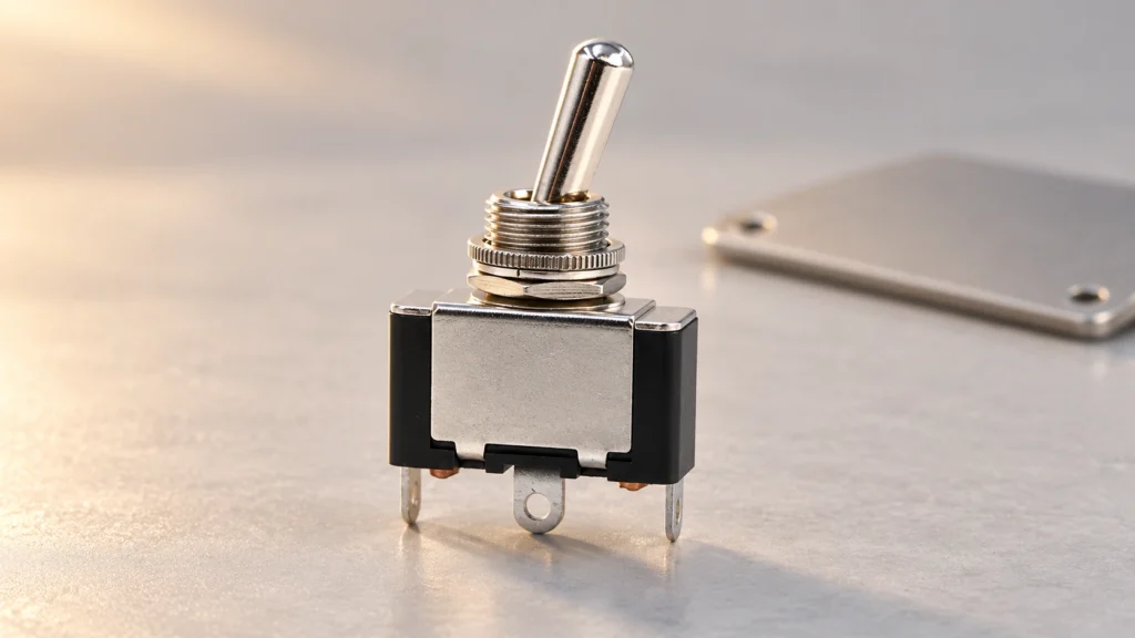
Preserve the original switching function A toggle switch replacement needs to match poles, throws, maintained or momentary action, contact ratings, panel mounting and terminal arrangement. The same number of pins or a similar metal lever does not establish interchangeability. Begin with the equipment circuit and original order code, build a contact-state table, and compare the candidate's current specification. For OEM equipment, a different part is a controlled substitution that requires functional validation. This guide focuses on panel-mounted equipment controls, including the LEMA toggle switch range, rather than household wall-switch wiring, musical-instrument modifications or vehicle-specific repairs. If the equipment manufacturer specifies an approved service part, use that instruction as the starting point. A generic selection checklist cannot override approval requirements or establish that an unlisted component is suitable. Preserve the original machine function and investigate why the old part failed before installing another switch. For the wider operating principle and selection context, see the toggle switch mechanism guide. For a termination comparison, use the solder, screw and quick-connect terminal guide. These references support the replacement comparison; the exact part drawing still controls acceptance. Document the old switch and its circuit Collect the complete switch markings, part number and any suffix. Photograph the actuator, panel mounting and terminal side after following the equipment isolation procedure. Note the orientation of the lever and any locating tab, keyed washer or anti-rotation feature. Record which position corresponds to the displayed equipment command and which circuits are connected in that position. Identify the connected load from the diagram. A toggle can carry load current directly, operate a relay coil or provide a controller input. Those roles impose different requirements. Document voltage, AC or DC, steady current...

Read More
Micro Switch Replacement: Matching Form, Fit and Function
Blog LEMA Electric

Micro Switch Replacement: Matching Form, Fit and Function

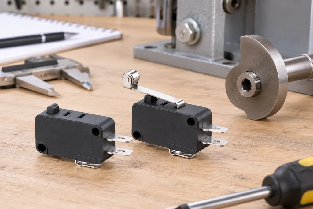
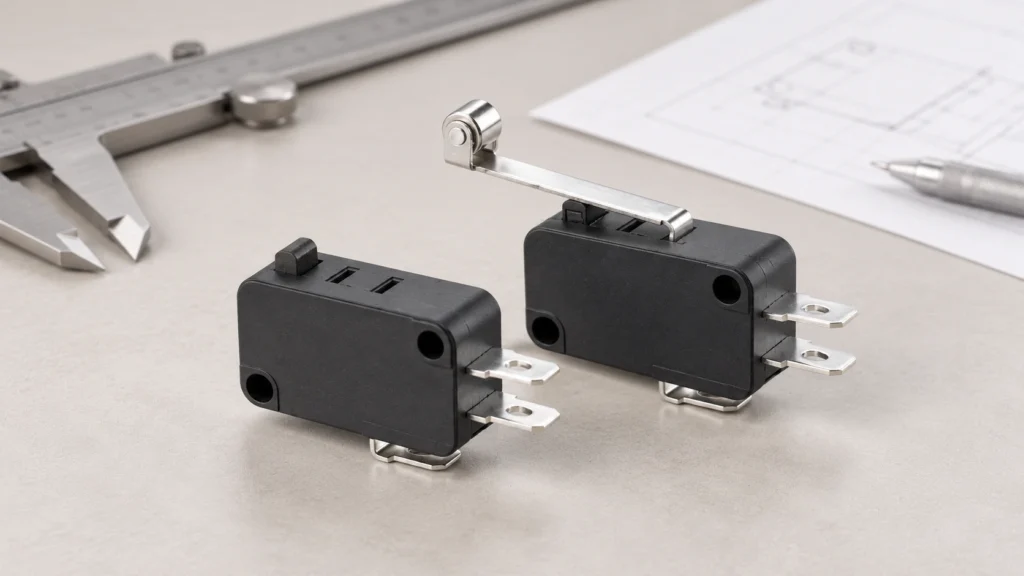
Match the replacement to the machine, not just the switch body A micro switch replacement must match the original contact function, mounting geometry, actuator movement, terminal arrangement and electrical duty. A switch that fits the screw holes can still change the operating point, reverse a control signal or fail prematurely under the connected load. Start with the equipment service instructions and the complete original part number, then compare the proposed replacement against a current drawing and rating sheet. For industrial and appliance assemblies, treat an undocumented substitution as an engineering change requiring validation. This guide explains how to build that comparison without assuming that similar-looking switches are interchangeable. The scope here is a mechanically actuated snap-action component, such as the models in the LEMA micro switch range. It does not provide an approval to replace a machine safety device, a sealed appliance assembly or a manufacturer's proprietary service part. Those cases may require an exact approved component or a complete assembly. Do not bypass an interlock to keep equipment running while a replacement is being sourced. Record the original installation before removing anything Identify the equipment, assembly revision and original switch order code. Photograph the switch from the actuator, mounting and terminal sides, with the circuit isolated. Record the markings exactly, including voltage, current, temperature codes and any separate load-specific ratings. A supplier logo or a partial family name is not enough: terminals, actuators and contact materials can vary within one product family. Record how the actuator contacts the moving mechanism. Note whether a cam touches a roller, a bracket presses a plunger, or a door deflects a lever. Include the normal rest position and the position at which the...

Read More
Push Button Switch Troubleshooting: Contacts, Wiring and Control Inputs
Blog LEMA Electric

Push Button Switch Troubleshooting: Contacts, Wiring and Control Inputs

Push button switch troubleshooting works best when you separate four possible faults: the actuator, the electrical contacts, the wiring, and the receiving control circuit. A button that feels normal can still have a bad connection; a working contact can still send a signal that the machine ignores. Begin with the circuit drawing and the expected released and pressed states, then isolate the machine before inspecting or measuring the switch. This guide helps industrial equipment builders and maintenance teams locate the fault without assuming that every failure requires a new button. The examples concern ordinary control inputs. Emergency stops, guard circuits and other protective functions require their own approved procedures and validation. Never bypass a protective device to keep production running. Record the symptom before moving any wires Write down exactly what fails: no response, delayed response, several responses from one press, a button that stays down, or an indicator lamp that stops working. Also record whether the failure occurs after cleaning, after vibration, at startup, or only after the equipment has been running. These conditions help distinguish a damaged component from installation stress or a problem elsewhere in the circuit. Identify the switch order code, drawing revision, terminal designations, control voltage, connected load and intended action. A maintained button should remain in its selected state; a momentary button should return when released. Mistaking one for the other produces a false diagnosis. Compare the installed device with the approved bill of materials rather than relying on color or appearance. Use the industrial push button selection guide to review the original application requirements. Troubleshooting should confirm those requirements, not quietly change them. Isolate energy before mechanical or continuity checks Stop the equipment...

Read More
How to Test a Foot Switch: Isolated Contact and Cable Checks
Blog LEMA Electric

How to Test a Foot Switch: Isolated Contact and Cable Checks

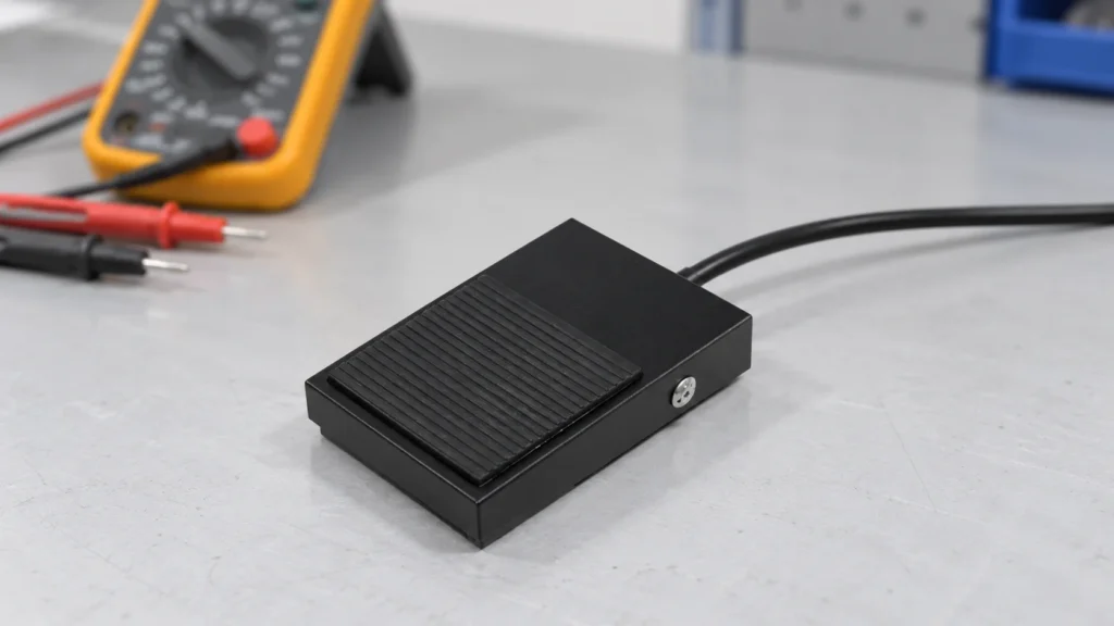
To test a foot switch, identify its intended contact function, safely isolate and disconnect it from the equipment, and check the specified contact pair in both released and operated states. A multimeter can help screen an ordinary mechanical switch for an open circuit or an inconsistent connection. It cannot establish a pedal's load rating, safety approval or suitability for a particular machine. This guide covers a repeatable inspection record for industrial foot controls, including the pedal, cable and connector, so you can distinguish a switch fault from a harness or controller problem. Do not apply this procedure unchanged to electronic, variable-speed, medical or safety-rated pedals. Their circuits and verification requirements may be different. Follow the exact equipment and pedal documentation. Identify the device before choosing a test A foot-operated device may be a simple contact switch, a potentiometer, an electronic sensor or a multi-stage control. Some pedal assemblies have several independent contacts. Others send a coded signal to a controller. Testing every pair of wires as though it were a dry contact can produce misleading results or damage an electronic assembly. Read the order code and terminal diagram. Record whether the action is momentary or maintained, whether the intended contact is normally open or normally closed, and whether the connector contains additional circuits. Do not infer function from a connector's shape, wire colors or the appearance of a similar pedal. The relevant drawing should describe the particular order code being tested. The industrial electric foot switch selection guide explains the wider specification questions. This test guide focuses on locating an existing fault without changing those requirements. Prepare an isolated, controlled test Follow the site's energy-control procedure and verify the safe...

Read More
Foot Switch for Pump Control: Action, Interface and OEM Checklist
Blog LEMA Electric

Foot Switch for Pump Control: Action, Interface and OEM Checklist

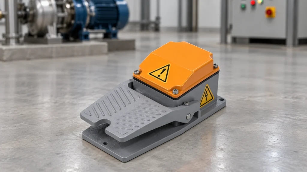
A foot switch for a pump should normally be selected as part of the pump's control system: define the required pedal action, identify the receiving input or switching device, and verify the complete electrical duty before connecting a load. A momentary pedal can request pumping while held; a maintained pedal can request a continuing state. Neither action automatically provides safe stopping, accurate dosing or protection against unexpected restart. This guide gives equipment builders a practical specification and validation checklist for electrical foot controls used around pumping operations. It concerns an electrical command device, not a pedal-operated mechanical pump or a pneumatic valve. An ordinary industrial pedal must not be assumed suitable for medical treatment, hazardous fluids or a safety function without the applicable system assessment. Describe the pumping task before choosing the pedal Start with the operator's task. Does the operator need both hands to position a container, hold a hose or align a fixture? Is the command intended to run the pump continuously, request a timed cycle or permit a process only while the pedal is held? These are different control functions. The same physical pedal can produce very different machine behavior depending on the receiving circuit. Record the fluid, pump type, location and consequences of an unintended command. Include the pressure and motion hazards, splash exposure, nearby moving equipment and the operator's working position. A hands-free command can be convenient while introducing a new risk of accidental operation. Decide how the overall machine prevents that event before specifying a pedal's color or enclosure material. The industrial foot switch selection guide provides the broader component-selection framework. The pump-specific questions below should become part of the equipment specification and acceptance...

Read More
Limit Switch Head Types and Adjustable Actuator Positions
Blog LEMA Electric

Limit Switch Head Types and Adjustable Actuator Positions

Limit switch heads should be chosen for the target motion, permitted approach direction and operating travel of the exact switch family. Roller levers, plungers, rods and other actuator forms are not interchangeable simply because they detect position. Some constructions allow a head to be repositioned under a defined procedure; others do not. Confirm the complete head and body combination, orientation options and instructions before changing an installed switch.This guide focuses on head selection and orientation for mechanical position switches. It complements the broad actuator-types and mounting guides, rather than giving universal instructions for rotating any head. LEMA LZ1 switch images are the real product reference; their external appearance does not prove field interchangeability with another series. Separate the head from the complete switch identity A position switch assembly includes the body, contact arrangement, head, actuator and mounting. A replacement head must match the relevant family and approved combination. Similar screw patterns or housing shapes do not prove that the internal operating relationship, sealing or travel is correct. Order and inspect the complete identified construction.Record the body and head codes where the maker provides them. If the head is not offered separately or no approved interchange information exists, do not assume it is a service part. Ask for the complete switch option instead. This avoids substituting a physically attachable head that changes the electrical or mechanical operation without an established acceptance basis. Describe the target approach in three dimensions Identify where the moving target contacts the actuator and how it approaches, passes and leaves. A roller lever can suit a cam profile, while a plunger may suit a controlled pressing direction. A rod or flexible actuator may detect movement over a...

Read More
Push Button Switch Debouncing for PLC and Microcontroller Inputs
Blog LEMA Electric

Push Button Switch Debouncing for PLC and Microcontroller Inputs

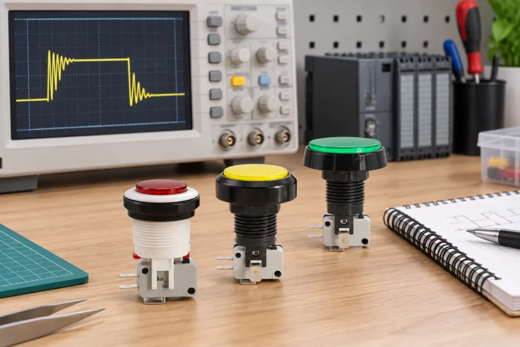
Push button debounce makes one intended operator action produce the intended controller event despite brief contact transitions. For ordinary PLC or microcontroller command inputs, first establish the raw electrical state, then accept a stable state and generate the required press or release event. Choose filtering from measured contact behavior and the acceptable response time; do not apply one fixed delay to every button or use filtering to hide defective wiring.This guide concerns normal operator commands such as selecting a mode or counting presses. It does not design an emergency-stop or other safety function. LEMA PBS push buttons are the illustration reference. The exact contact arrangement, action and controller input requirements still need confirmation for the chosen model. Define the command before choosing a filter Write down what one press is supposed to do. It may toggle a mode, increment a value, issue a single start request or hold a manual command while pressed. Those functions require different event logic even when the physical button is identical. Identify whether press, release or both transitions matter and whether a held button should repeat.Create acceptance examples before implementation: one press gives one event; holding gives the specified behavior; a rapid second press is accepted or intentionally rejected according to the requirement. Also define startup behavior when the button is already held. A filter can produce a stable state but still create the wrong command if the event rules are incomplete. Distinguish contact bounce from other signal problems Moving contacts can settle through several transitions around one actuation. The University of Washington Makeability Lab lesson explains this basic contact-bounce mechanism. A trace that continues changing while the button is held can have another cause,...

Read More
Heavy-Duty Limit Switch Selection: A Field Checklist for Industrial OEMs
Blog LEMA Electric

Heavy-Duty Limit Switch Selection: A Field Checklist for Industrial OEMs

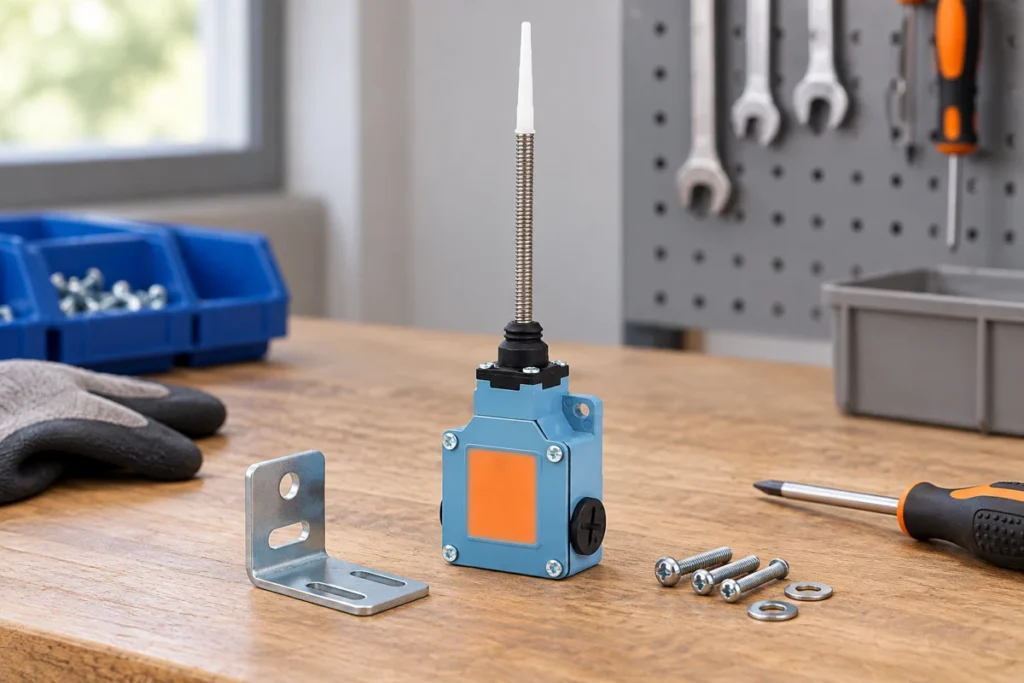
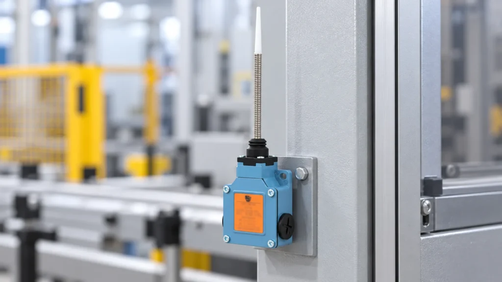
Product-based illustration generated from the LZ1 product photograph. The mounting scene is illustrative; confirm the exact model, actuator and installation conditions against its drawing. A heavy-duty limit switch should be selected by the loads and environment it must survive—not by the adjective on a catalog page. Start with the machine motion and the required switching point, then match an actuator, mounting position, enclosure protection, contact duty and service plan to that application. Ask for model-specific ratings and test evidence; “heavy duty” is not a universal certification or a substitute for an equipment risk assessment. LEMA’s LZ1 Series page, for example, lists an aluminum-alloy limit switch with an IP66 enclosure rating and separate AC-15 and DC-13 contact ratings. Those claims apply to the stated series information and must still be checked against the exact order code and machine design. Define what “heavy duty” must withstand Write down the stresses before comparing part numbers. A press, conveyor, hydraulic cylinder, outdoor mechanism and washdown machine can all be described as demanding, but they do not impose the same stresses. One may need a robust actuator and repeatable switching position; another may need a sealed enclosure, a corrosion-resistant mounting arrangement or a long cable-flex life. Treat each requirement separately instead of assuming that one rating covers every condition. Build a short use profile: expected operating cycles, target approach speed, likely impact or side load, vibration, dust, liquid, cleaning chemistry, ambient temperature, cable movement and access for maintenance. Identify the consequence of a missed or false transition. If the switch is part of a safety-related control function, specify the required safety architecture and validated components separately; a general-purpose limit switch by itself does not establish...

Read More
Dustproof Micro Switch Selection for Industrial Equipment
Blog LEMA Electric

Dustproof Micro Switch Selection for Industrial Equipment

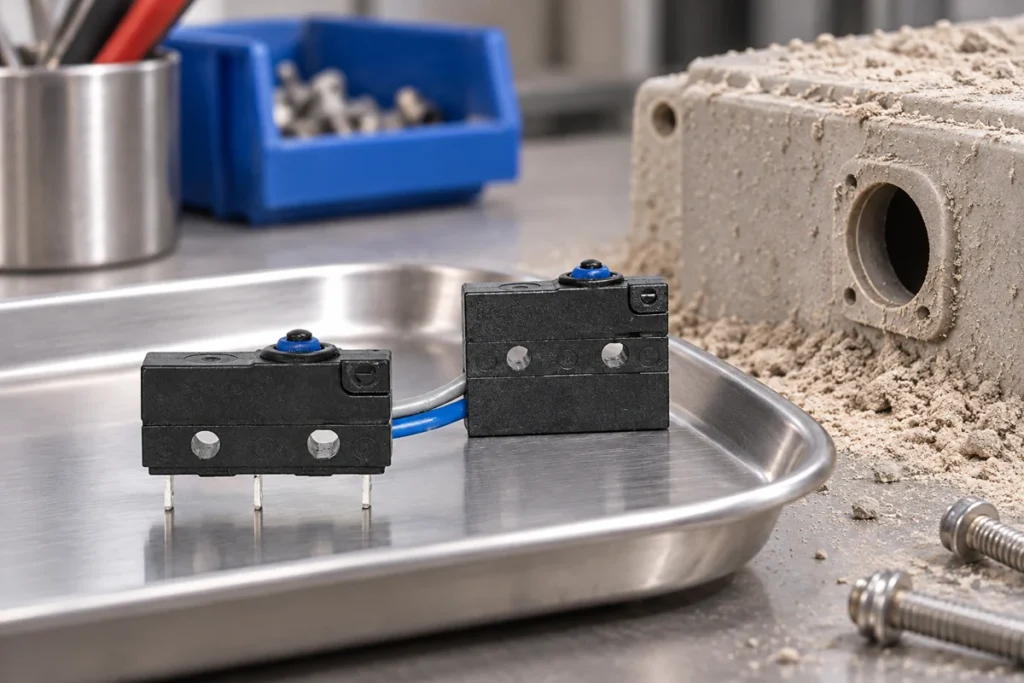
A dustproof micro switch must be selected from documented ingress protection and the actual installation boundary, not a sealed-looking housing or a general waterproof label. Identify the dust exposure, actuator movement, cable or terminal entry paths and surrounding enclosure. Then confirm the exact switch variant's evidence and validate its function in the intended mechanism. A switch body can resist ingress while dust still obstructs the external roller, lever or target.This guide focuses on industrial position and mechanism inputs. It excludes mouse-click sound comparisons and does not claim that every LEMA waterproof micro switch has a particular dust classification. The KW12F wired switch family is the real product reference; request the applicable construction and test information for the order code being considered. Describe the dust before choosing the switch Record what generates the dust and where it reaches the mechanism. Dry process powder, fibers, wood residue and abrasive particles create different practical problems. Include particle accumulation, airflow, cleaning methods and whether liquid or oil makes the dust adhere. A simple label such as dusty workshop does not give the supplier enough information to evaluate the application.Identify the function and consequence of a missed or unstable input. A production-position indication and a safety-related interlock can need different system architecture and validation. Do not elevate a general micro switch to a safety device because it is sealed. The equipment design authority must establish the required function and approved control arrangement. Read the ingress classification correctly IEC 60529 provides the IP classification framework for enclosure protection. For a switch, ask for the full relevant classification and conditions tied to the exact construction. Do not infer dust performance solely from a water-related description. A statement...

Read More
How to Choose a Micro Switch Lever Length
Blog LEMA Electric

How to Choose a Micro Switch Lever Length

Micro switch lever length should be chosen from the mechanism's motion, contact point, required operating force and permitted travel. A longer lever can change mechanical advantage, but it also changes displacement and the moving envelope. Measure from the relevant pivot or reference defined in the switch drawing, not merely the exposed metal strip. Select a complete actuator variant and verify operation and release in the real mechanism rather than bending a stock lever until it seems to work.This guide focuses on choosing lever geometry for repeatable OEM position detection. It complements the broader actuator-types and force-selection guides. LEMA KW7 roller-lever micro switches are the product reference; the illustrations are not dimensioned drawings or permission to modify the actuator. Define what the mechanism needs to detect Start with the target event: a part reaches a position, a cam rotates through a point, a door closes or an item passes a sensing station. Record both the required operating state and the release state. Decide whether the controller needs a held condition, a pulse or a change of state. Lever selection must support that function across the expected movement.Identify the available motion at the intended switch location. Include approach direction, displacement, speed and how accurately the target is guided. A lever that reaches a distant target may solve packaging but introduce sensitivity to lateral motion. Where the target location is uncertain, compare a different mounting position before assuming that a longer lever is the best correction. Read the actuator-specific drawing Obtain the full switch order code and drawing for the actual lever or roller option. Identify the pivot, permitted contact region, operating position, release behavior and maximum allowed travel. A body-family drawing without...

Read More
Toggle Switch Sealing Washer and O-Ring Selection
Blog LEMA Electric

Toggle Switch Sealing Washer and O-Ring Selection

A toggle switch sealing washer closes a specific path at the panel interface when its material, geometry and compression match the approved switch assembly. It is different from a lock washer, an anti-rotation washer and a lever boot. Select the seal using the switch bushing drawing, finished panel, exposure conditions and maker's assembly instructions. Adding an arbitrary O-ring or tightening the nut harder does not establish waterproof performance.This guide focuses on the seal around a panel-mounted toggle bushing. It complements whole-switch environmental selection and boot selection. The LEMA LT3232B waterproof-toggle family is the product reference; its photograph does not establish that any aftermarket washer produces a particular IP rating. Map every relevant entry path Identify where moisture or dust could move into the enclosure: around the bushing, through the lever mechanism, along a threaded accessory or through rear connections. A panel washer addresses only the interface it is designed to seal. Even a correctly installed washer cannot make an unrelated opening watertight or protect exposed rear wiring.Review the complete assembly instead of the accessory in isolation. Record the switch model, panel, nut, seal and any boot together. Ask which combination was evaluated for the claimed environment and how it was mounted during that evaluation. This prevents a component-level claim from being applied automatically to the finished equipment. Distinguish sealing from locking and anti-rotation A lock washer is intended to help the fastener arrangement resist loosening. An anti-rotation washer or keyed feature limits body rotation. A sealing washer creates the specified barrier at the panel interface. These functions can be combined in an approved assembly, but one should not be assumed to replace another.Use the stack order in the supplier instructions....

Read More
Power Socket Terminal Types: Solder, Quick Connect and PCB
Blog LEMA Electric

Power Socket Terminal Types: Solder, Quick Connect and PCB

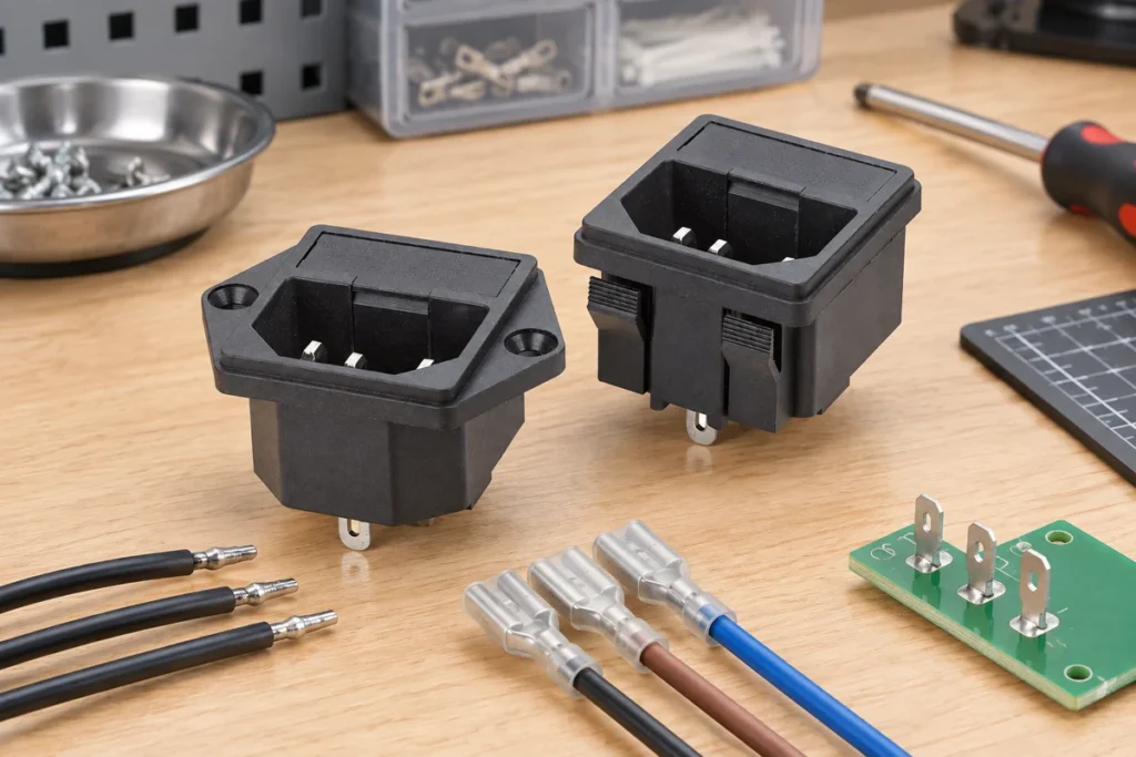
Power socket terminal types determine how an equipment inlet connects to its internal circuit. Solder lugs need a controlled soldering process and supported wires; quick-connect tabs need compatible receptacles and documented crimps; PCB pins need an exact footprint and a board design suitable for the circuit. The connection style is separate from the inlet's mating designation, current rating and protective-earth arrangement. Select the complete inlet variant and termination system together.This guide concerns equipment power inlets, including LEMA IPZ products. It does not describe household outlet installation or assume that every IPZ variant offers every terminal option. Confirm available constructions, electrical identity and mounting details from the specific model drawing before ordering or connecting a part. Start with circuit identity and the rear view Identify the equipment circuit and the inlet terminals from its actual marking and drawing. A rear view can reverse the apparent left and right relationship compared with the mating face. Never identify line, neutral or protective earth solely from a familiar photograph. Record viewing direction on the wiring drawing and check it against the approved sample.Where the circuit includes a fuse, switch or filter, establish the connection paths for that exact module. A similar housing can contain a different arrangement. Keep terminal function separate from terminal shape. Use qualified personnel and a safely isolated assembly for inspection; a connection guide cannot replace the equipment's electrical design, approved procedure or applicable safety evaluation. Specify solder lugs as a production process Obtain the permitted wire size, attachment method and soldering exposure from the component maker. Define the soldering equipment, materials, process window and inspection criteria. Do not let operators compensate for an unsuitable connection by applying progressively more heat...

Read More