
Micro switch terminal coplanarity inspection is useful only when the selected terminal configuration and assembly drawing define which surfaces should share a plane. First confirm the switch variant, intended connection and reference features. Then measure the specified terminal locations using a method that does not bend them into an apparent pass. Spade tabs, solder terminals and board-mount leads should not inherit the same assumed requirement. For an OEM order, request the controlled terminal drawing and acceptance criteria before buying a generic coplanarity test. This guide explains how to organize that evidence without inventing a KW7 tolerance or treating every microswitch as a surface-mount component.
Confirm that coplanarity is the actual assembly concern
Terminal position relative to an intended common plane is separate from terminal strength, solderability and contact resistance. Identify the assembly feature that needs alignment. A harness using individual receptacles may have a different concern from a rigid board interface. Do not choose the test merely because the terminal ends look uneven in a perspective photograph.
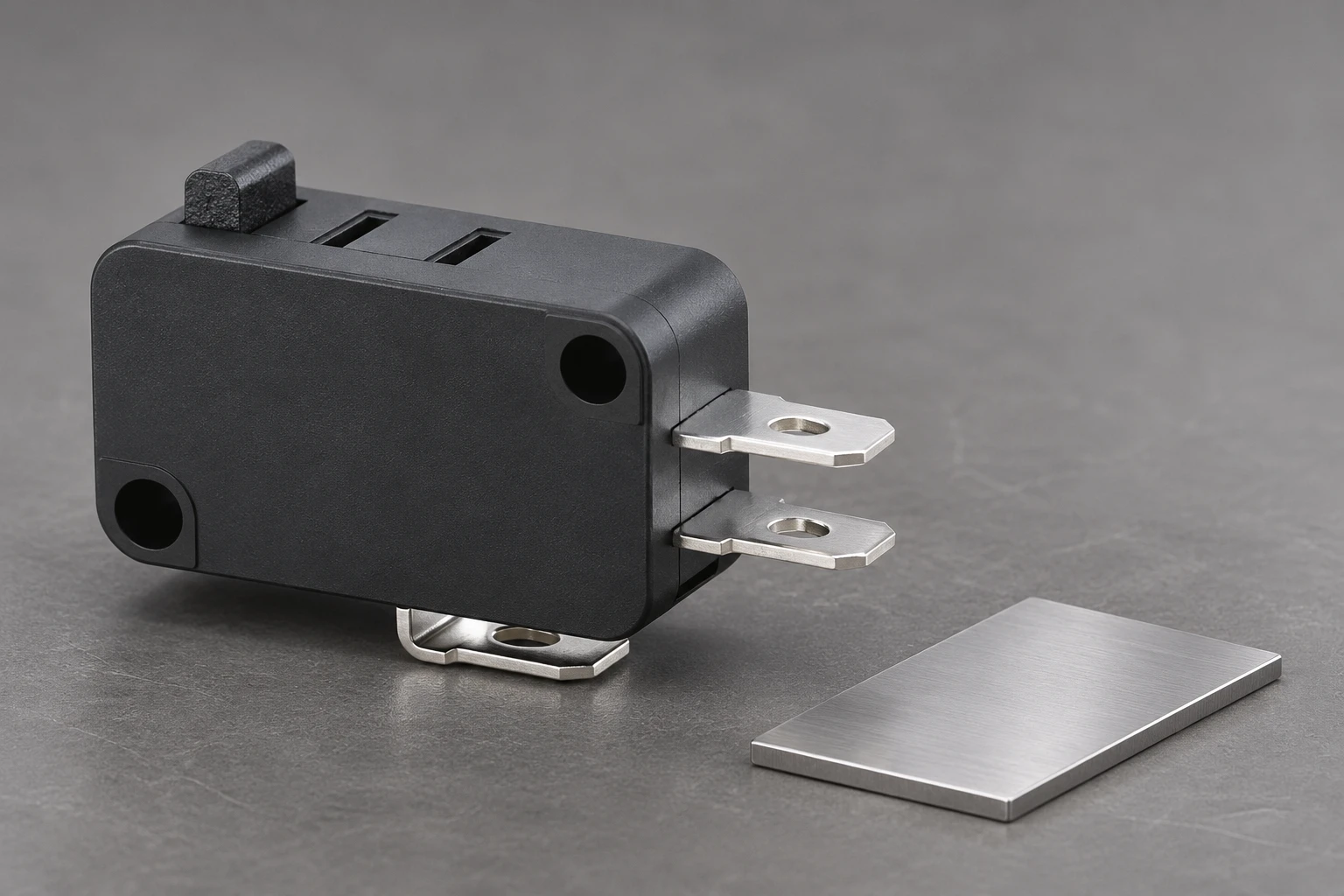
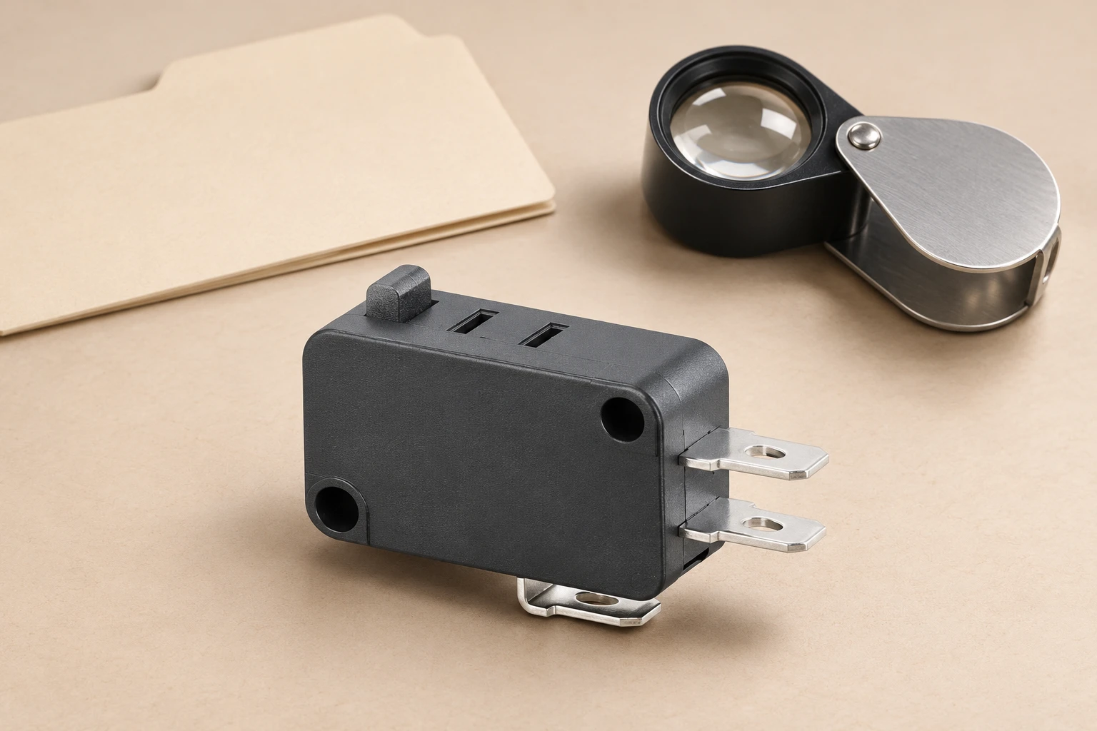
The KW7 Series Micro Switch KW7-0 Black Switch with CE CQC presents a family with different actuator and terminal options. Confirm the purchased version with the supplier rather than treating one catalog image as a complete dimensional drawing. The micro switch terminal types guide helps organize those connection choices before a dimensional review.
If the assembly interference is actually caused by terminal spacing, angle or clearance, call it that. A coplanarity report may not capture those characteristics. Mark the specific contact region or lead feature on the approved drawing and explain how it interacts with the mating part. The inspection request should answer that interface question.
Establish the reference before collecting heights
Ask which features locate the switch in the intended assembly. The body may be supported by mounting features rather than the terminals. Resting the unit on terminal tips can therefore create a reference unrelated to its installed position. Use the drawing and an agreed setup to determine how the part is located during inspection.
The NIST dimensional measurement services overview describes length-based calibration and dimensional measurement work. It is background for asking about measurement capability and traceability. It does not provide a KW7 terminal tolerance, fixture design or acceptance plane.
Keep the chosen reference stable while observing the required terminals. Record which terminal locations were accessible and whether the fixture hid any part of the feature. If a laboratory proposes a fitted reference plane, ask how that plane relates to the drawing requirement. A mathematical best fit should not silently replace the specified datum arrangement.
| Evidence item | What to verify | Decision supported |
|---|---|---|
| Configuration | Confirm terminal option and controlled drawing | Avoid applying an unrelated lead requirement |
| Reference | Identify body support and specified datum features | Heights relate to the assembly interface |
| Method | Document access, probe approach and part restraint | Inspection does not force terminals into position |
| Results | Retain each feature identity, location and unit | A displaced terminal remains distinguishable |
| Disposition | Apply the agreed tolerance and decision rule | Inspection supports a defined release decision |
Prevent the fixture from changing the result
Inspect the switch in a de-energized, unconnected state under an approved handling procedure. Avoid pushing on terminal ends to hold the body steady. A clamp or probe that moves the terminal can change the characteristic being measured. Agree the support and contact conditions with the inspection provider before accepting numerical results.
A noncontact method can avoid probe force, but it still needs a validated view of the feature. Reflections, occlusion and ambiguous edges can affect what the instrument detects. Ask the provider how the actual terminal finish and geometry were handled. Do not assume that an attractive three-dimensional image proves the correct feature was measured.
For a contact method, request an explanation of the selected probe approach and how part movement was controlled. Keep fixture photographs with the inspection record. A second operator should be able to understand the setup without relying on an informal demonstration. Report limitations instead of filling inaccessible locations with estimated values.
Ask for results that retain terminal identity
Label the measured features using the approved drawing identifiers. Record the measured locations, units and sign convention where relevant. Preserve individual terminal results rather than only the largest reported deviation. This lets the assembly team distinguish a consistent shift from one displaced terminal or a setup problem.
The NIST traceability guidance explains that traceability concerns measurement results and their calibration chain, including uncertainty. Use that principle when reviewing a dimensional report. A sticker on an instrument alone does not tell the buyer whether this particular setup can resolve the characteristic required by the order.
Ask the responsible quality team to review uncertainty against the specified tolerance and decision rule. Do not select an instrument solely because its display has many decimal places. If the requirement is not defined, record an observation or exploratory measurement and request engineering disposition; do not convert it into a formal acceptance certificate.
Separate incoming condition from assembly-induced movement
Keep an as-received sample when investigating a fit complaint. Compare its condition with a specimen that has passed through the actual assembly process, using traceable identities. If terminals are different afterward, investigate handling and joining operations as well as the incoming supply. A changed specimen cannot retrospectively establish how it arrived.
The terminal mechanical strength guide addresses loads and retention questions. The terminal solderability after storage guide addresses a different joining concern. These checks may support an overall investigation, but neither replaces the dimensional requirement described here.
Do not straighten a terminal to make a sample fit and then present its measurement as an incoming result. Any rework needs an authorized process and a separate record. Preserve the original finding, the disposition and the identity of the reworked sample. A corrected geometry does not automatically establish that other relevant characteristics remain acceptable.
Use sampling and comparison deliberately
Define which lot or configuration the inspection represents. Mixing terminal variants into one data set can produce apparent variation that simply reflects different drawings. Record package position or handling history when those factors are relevant to the complaint. Use the agreed sampling plan rather than claiming that a few convenient specimens represent every delivery.
For a supplier comparison, share the same feature definitions and setup before exchanging results. If one laboratory supports the body and another supports the terminals, their numbers may answer different questions. Review the procedure and raw observations before deciding that the product has changed or that either laboratory is wrong.
Where repeat measurements are required, distinguish removing and replacing the same specimen from simply repeating a reading without changing the setup. These exercises reveal different sources of variation. Retain both records and explain the purpose of the repeat. Do not discard inconvenient results without a documented technical reason.
Build an inquiry that leads to an assembly decision
Provide the selected switch code, terminal drawing revision, mating interface and the characteristic that causes concern. Ask whether the requested plane and locations are part of the current product specification. Include photographs that show orientation and the full assembly context, while avoiding an unsupported diagnosis such as “bent from production.”
If the characteristic needs a custom requirement, agree feasibility, sampling and the evidence supplied with production before placing the order. Clarify whether inspection covers loose components, completed switches or the finished assembly. These are different stages, and a satisfactory result at one stage does not automatically release all later work.
End with a decision linked to the actual interface: accept the inspected lot against the agreed requirement, hold for missing dimensional evidence, or revise the assembly through engineering review. Keep the report, fixture record and drawing together. That packet is more useful for future orders than a generic note that the terminals were checked and looked level.
Example: a terminal that misses its mating interface
Suppose a terminal does not align with a rigid mating feature. Record which terminal and which mating feature are involved, then compare both with their drawings. Check whether the displacement is lateral, angular or relative to a required plane. This distinction determines the measurement request. Do not bend the terminal or enlarge the mating feature before the responsible engineer reviews the original condition.
Further learning
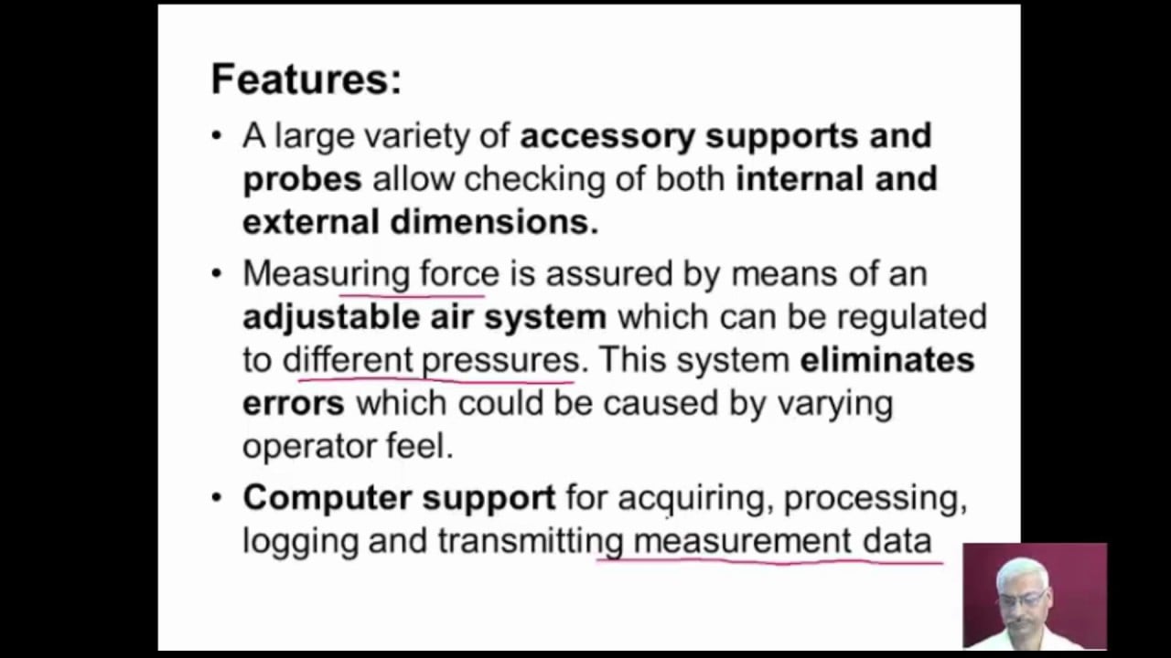
This nptelhrd metrology lecture introduces universal and coordinate measuring machines. It helps readers understand dimensional measurement methods before discussing terminal geometry with an inspection provider; it does not specify KW7 terminal tolerances.
Frequently asked questions
Do all micro switch terminals need one common plane?
No universal requirement is established here. The terminal configuration, connection method and controlled drawing determine whether a common-plane characteristic is relevant.
Can a photograph prove terminal coplanarity?
A perspective photograph is useful for identification and visible condition. It does not by itself provide a traceable dimensional result against a specified plane.
Does electrical continuity prove the terminal geometry is acceptable?
No. Continuity concerns an electrical path. Terminal position and assembly fit require their own relevant evidence.
Can a terminal be bent before measurement?
Preserve incoming condition. Any authorized rework should be recorded separately, with subsequent inspection appropriate to the approved process.