LEMA NEWS CENTER

News & Blog

News Center

How to Test a Micro Switch With a Multimeter
Blog LEMA Electric

How to Test a Micro Switch With a Multimeter

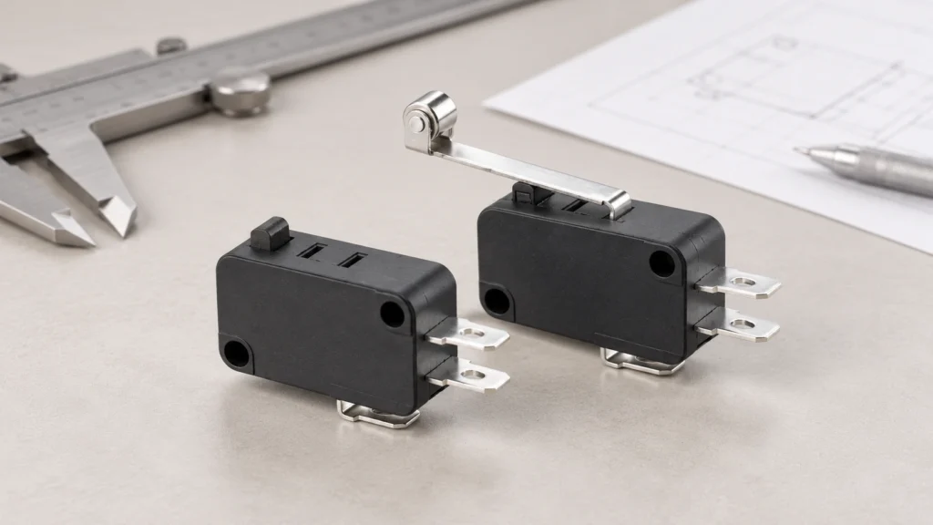
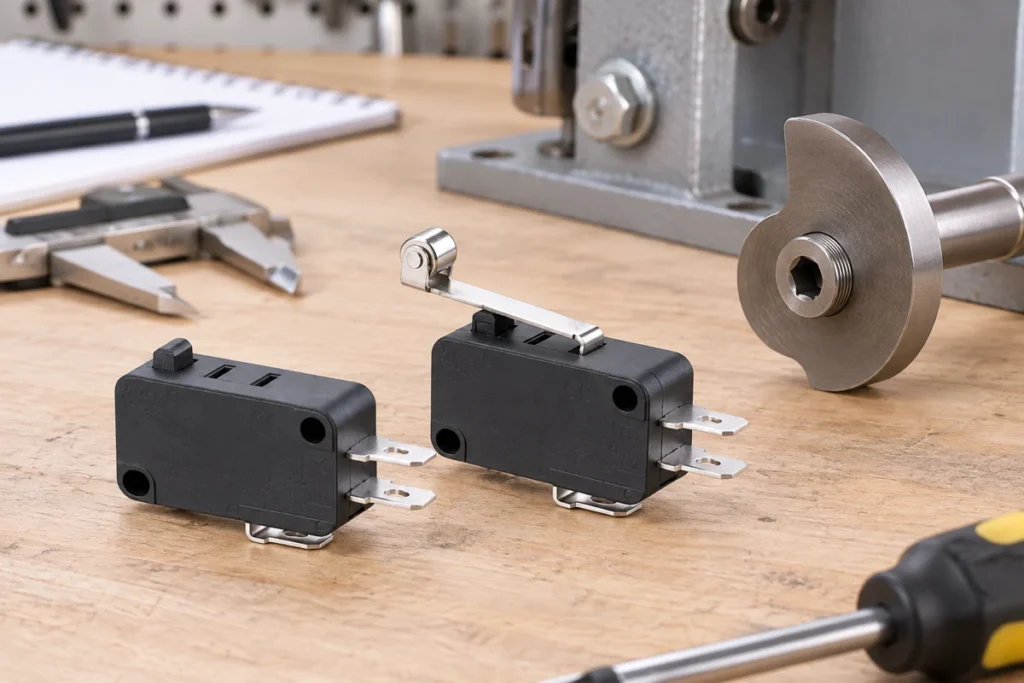
How to test a micro switch with a multimeter should be selected by matching the electrical function, mechanical interface, environment, and verification plan—not by copying a generic diagram or choosing from appearance alone. A multimeter continuity test can confirm whether a micro switch changes state, but it cannot prove load capacity, insulation condition, environmental sealing, or remaining service life. Testing should be de-energized, isolated from the circuit, and interpreted with the COM, NO, and NC terminal arrangement for the exact model. This guide gives engineers and OEM buyers a practical way to define the requirement, compare samples, and avoid a part that works on the bench but fails after installation. Application-focused view using the matching LEMA product. What the term means in this application A multimeter continuity test can confirm whether a micro switch changes state, but it cannot prove load capacity, insulation condition, environmental sealing, or remaining service life. Testing should be de-energized, isolated from the circuit, and interpreted with the COM, NO, and NC terminal arrangement for the exact model. The first job is to separate the switch's name from its required behavior. Product names are often shortened for search or purchasing, while an engineering drawing defines the contact state, terminal numbering, operating point, allowable travel, mounting reference, and ratings. If those details are missing, two parts with similar names may behave differently. Write the control requirement as a short sequence: the condition before actuation, the physical action that causes actuation, the electrical state after actuation, and the condition that resets it. This sequence prevents confusion between mechanical action and contact logic. It also gives the controls engineer, mechanical designer, buyer, and supplier one shared description to review....

Read More
IEC C16 Hot-Condition Inlet: Uses and Temperature Rating
Blog LEMA Electric

IEC C16 Hot-Condition Inlet: Uses and Temperature Rating

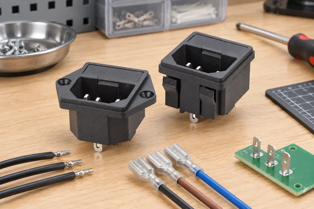
Iec c16 inlet should be selected by matching the electrical function, mechanical interface, environment, and verification plan—not by copying a generic diagram or choosing from appearance alone. The C16 appliance inlet resembles C14 but is intended for hot-condition applications within the applicable IEC 60320 system. The matching connector has a different keying detail. Designers must confirm the complete inlet-connector pair, temperature class, ratings, mounting, and certification for the finished appliance. This guide gives engineers and OEM buyers a practical way to define the requirement, compare samples, and avoid a part that works on the bench but fails after installation. Application-focused view using the matching LEMA product. What the term means in this application The C16 appliance inlet resembles C14 but is intended for hot-condition applications within the applicable IEC 60320 system. The matching connector has a different keying detail. Designers must confirm the complete inlet-connector pair, temperature class, ratings, mounting, and certification for the finished appliance. The first job is to separate the switch's name from its required behavior. Product names are often shortened for search or purchasing, while an engineering drawing defines the contact state, terminal numbering, operating point, allowable travel, mounting reference, and ratings. If those details are missing, two parts with similar names may behave differently. Write the control requirement as a short sequence: the condition before actuation, the physical action that causes actuation, the electrical state after actuation, and the condition that resets it. This sequence prevents confusion between mechanical action and contact logic. It also gives the controls engineer, mechanical designer, buyer, and supplier one shared description to review. Do not treat a catalog current rating as a universal permission to switch any load. Contact...

Read More
2-Pin Push Button Switch Wiring Diagram
Blog LEMA Electric

2-Pin Push Button Switch Wiring Diagram

2 pin push button switch wiring diagram should be selected by matching the electrical function, mechanical interface, environment, and verification plan—not by copying a generic diagram or choosing from appearance alone. A two-pin push button usually provides one contact path, but it may be normally open, normally closed, momentary, or maintained. The two terminals are generally non-polarized for a plain dry contact, yet illumination or electronic modules change that assumption. Verify the exact part before wiring. This guide gives engineers and OEM buyers a practical way to define the requirement, compare samples, and avoid a part that works on the bench but fails after installation. Application-focused view using the matching LEMA product. What the term means in this application A two-pin push button usually provides one contact path, but it may be normally open, normally closed, momentary, or maintained. The two terminals are generally non-polarized for a plain dry contact, yet illumination or electronic modules change that assumption. Verify the exact part before wiring. The first job is to separate the switch's name from its required behavior. Product names are often shortened for search or purchasing, while an engineering drawing defines the contact state, terminal numbering, operating point, allowable travel, mounting reference, and ratings. If those details are missing, two parts with similar names may behave differently. Write the control requirement as a short sequence: the condition before actuation, the physical action that causes actuation, the electrical state after actuation, and the condition that resets it. This sequence prevents confusion between mechanical action and contact logic. It also gives the controls engineer, mechanical designer, buyer, and supplier one shared description to review. Do not treat a catalog current rating as...

Read More
Foot Switch Connector Types for OEM Equipment
Blog LEMA Electric

Foot Switch Connector Types for OEM Equipment

Foot switch connector types should be selected by matching the electrical function, mechanical interface, environment, and verification plan—not by copying a generic diagram or choosing from appearance alone. Connector selection for a foot switch is an interface decision, not a cosmetic option. Pin count, keying, locking, current rating, ingress protection, cable flex life, shielding, mating cycles, and field replacement all affect whether the pedal remains reliable in service. This guide gives engineers and OEM buyers a practical way to define the requirement, compare samples, and avoid a part that works on the bench but fails after installation. Application-focused view using the matching LEMA product. What the term means in this application Connector selection for a foot switch is an interface decision, not a cosmetic option. Pin count, keying, locking, current rating, ingress protection, cable flex life, shielding, mating cycles, and field replacement all affect whether the pedal remains reliable in service. The first job is to separate the switch's name from its required behavior. Product names are often shortened for search or purchasing, while an engineering drawing defines the contact state, terminal numbering, operating point, allowable travel, mounting reference, and ratings. If those details are missing, two parts with similar names may behave differently. Write the control requirement as a short sequence: the condition before actuation, the physical action that causes actuation, the electrical state after actuation, and the condition that resets it. This sequence prevents confusion between mechanical action and contact logic. It also gives the controls engineer, mechanical designer, buyer, and supplier one shared description to review. Do not treat a catalog current rating as a universal permission to switch any load. Contact behavior changes with AC or...

Read More
DPST Toggle Switch Wiring for Two-Circuit Isolation
Blog LEMA Electric

DPST Toggle Switch Wiring for Two-Circuit Isolation

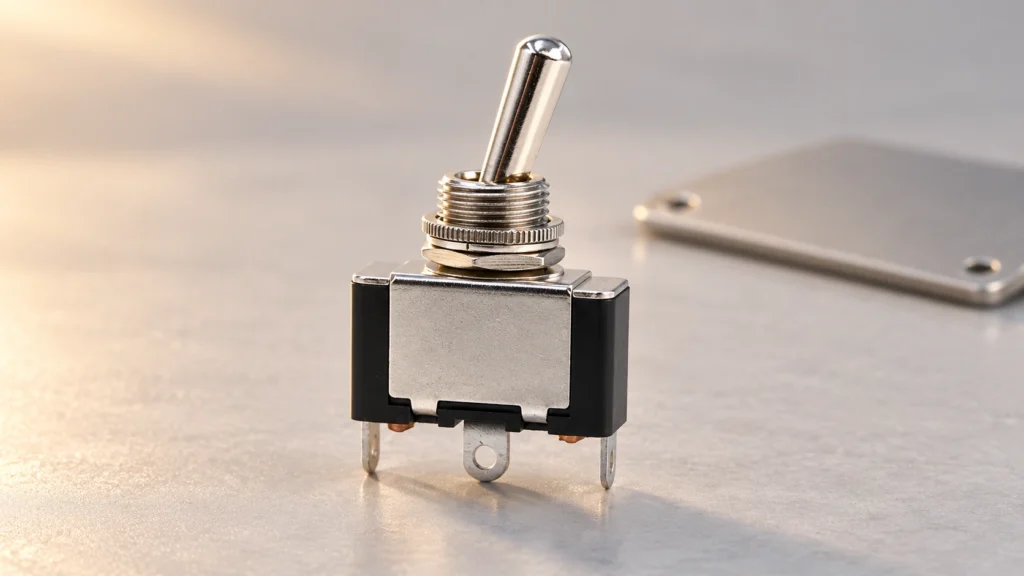
Dpst toggle switch wiring should be selected by matching the electrical function, mechanical interface, environment, and verification plan—not by copying a generic diagram or choosing from appearance alone. A DPST toggle contains two poles that change state together for simple two-circuit on/off isolation. It is not the same as DPDT, which provides two throws per pole. Terminal position varies by model, so continuity must be verified against the manufacturer's diagram before conductors are connected. This guide gives engineers and OEM buyers a practical way to define the requirement, compare samples, and avoid a part that works on the bench but fails after installation. Application-focused view using the matching LEMA product. What the term means in this application A DPST toggle contains two poles that change state together for simple two-circuit on/off isolation. It is not the same as DPDT, which provides two throws per pole. Terminal position varies by model, so continuity must be verified against the manufacturer's diagram before conductors are connected. The first job is to separate the switch's name from its required behavior. Product names are often shortened for search or purchasing, while an engineering drawing defines the contact state, terminal numbering, operating point, allowable travel, mounting reference, and ratings. If those details are missing, two parts with similar names may behave differently. Write the control requirement as a short sequence: the condition before actuation, the physical action that causes actuation, the electrical state after actuation, and the condition that resets it. This sequence prevents confusion between mechanical action and contact logic. It also gives the controls engineer, mechanical designer, buyer, and supplier one shared description to review. Do not treat a catalog current rating as a...

Read More
Hermetically Sealed Limit Switch: Uses and Selection Criteria
Blog LEMA Electric

Hermetically Sealed Limit Switch: Uses and Selection Criteria

Hermetically sealed limit switch should be selected by matching the electrical function, mechanical interface, environment, and verification plan—not by copying a generic diagram or choosing from appearance alone. Hermetic sealing uses a sealed envelope intended to prevent gas or moisture exchange through the enclosure. It is different from a boot or ordinary water-resistant housing. Selection must address the actual atmosphere, pressure, temperature cycling, lead sealing, contact load, and evidence for the claimed construction. This guide gives engineers and OEM buyers a practical way to define the requirement, compare samples, and avoid a part that works on the bench but fails after installation. Application-focused view using the matching LEMA product. What the term means in this application Hermetic sealing uses a sealed envelope intended to prevent gas or moisture exchange through the enclosure. It is different from a boot or ordinary water-resistant housing. Selection must address the actual atmosphere, pressure, temperature cycling, lead sealing, contact load, and evidence for the claimed construction. The first job is to separate the switch's name from its required behavior. Product names are often shortened for search or purchasing, while an engineering drawing defines the contact state, terminal numbering, operating point, allowable travel, mounting reference, and ratings. If those details are missing, two parts with similar names may behave differently. Write the control requirement as a short sequence: the condition before actuation, the physical action that causes actuation, the electrical state after actuation, and the condition that resets it. This sequence prevents confusion between mechanical action and contact logic. It also gives the controls engineer, mechanical designer, buyer, and supplier one shared description to review. Do not treat a catalog current rating as a universal permission...

Read More
Micro Switch Pretravel, Overtravel and Differential Travel Explained
Blog LEMA Electric

Micro Switch Pretravel, Overtravel and Differential Travel Explained

Micro switch pretravel overtravel differential should be selected by matching the electrical function, mechanical interface, environment, and verification plan—not by copying a generic diagram or choosing from appearance alone. Pretravel is actuator movement before contact transfer; overtravel is the permitted movement after transfer; differential travel is the distance between operate and release points. These terms describe different parts of the motion envelope and should never be substituted for one another on a drawing or inspection report. This guide gives engineers and OEM buyers a practical way to define the requirement, compare samples, and avoid a part that works on the bench but fails after installation. Application-focused view using the matching LEMA product. What the term means in this application Pretravel is actuator movement before contact transfer; overtravel is the permitted movement after transfer; differential travel is the distance between operate and release points. These terms describe different parts of the motion envelope and should never be substituted for one another on a drawing or inspection report. The first job is to separate the switch's name from its required behavior. Product names are often shortened for search or purchasing, while an engineering drawing defines the contact state, terminal numbering, operating point, allowable travel, mounting reference, and ratings. If those details are missing, two parts with similar names may behave differently. Write the control requirement as a short sequence: the condition before actuation, the physical action that causes actuation, the electrical state after actuation, and the condition that resets it. This sequence prevents confusion between mechanical action and contact logic. It also gives the controls engineer, mechanical designer, buyer, and supplier one shared description to review. Do not treat a catalog current...

Read More
IEC C13 vs C14: Connector Differences and Compatibility
Blog LEMA Electric

IEC C13 vs C14: Connector Differences and Compatibility

C13 vs c14 should be selected by matching the electrical function, mechanical interface, environment, and verification plan—not by copying a generic diagram or choosing from appearance alone. C13 is a cord connector and C14 is the matching appliance inlet in the common IEC 60320 family. They are complementary parts, not interchangeable names. Compatibility also depends on current, voltage, temperature class, cord construction, approvals, and the equipment's inlet orientation. This guide gives engineers and OEM buyers a practical way to define the requirement, compare samples, and avoid a part that works on the bench but fails after installation. Application-focused view using the matching LEMA product. What the term means in this application C13 is a cord connector and C14 is the matching appliance inlet in the common IEC 60320 family. They are complementary parts, not interchangeable names. Compatibility also depends on current, voltage, temperature class, cord construction, approvals, and the equipment's inlet orientation. The first job is to separate the switch's name from its required behavior. Product names are often shortened for search or purchasing, while an engineering drawing defines the contact state, terminal numbering, operating point, allowable travel, mounting reference, and ratings. If those details are missing, two parts with similar names may behave differently. Write the control requirement as a short sequence: the condition before actuation, the physical action that causes actuation, the electrical state after actuation, and the condition that resets it. This sequence prevents confusion between mechanical action and contact logic. It also gives the controls engineer, mechanical designer, buyer, and supplier one shared description to review. Do not treat a catalog current rating as a universal permission to switch any load. Contact behavior changes with AC...

Read More
Normally Open vs Normally Closed Push Button Switch
Blog LEMA Electric

Normally Open vs Normally Closed Push Button Switch

Normally open vs normally closed push button should be selected by matching the electrical function, mechanical interface, environment, and verification plan—not by copying a generic diagram or choosing from appearance alone. Normally open and normally closed describe the electrical state when the button is not actuated. They do not describe momentary versus maintained action. The safest choice depends on the control objective, fault response, monitoring logic, and the requirements of the finished machine. This guide gives engineers and OEM buyers a practical way to define the requirement, compare samples, and avoid a part that works on the bench but fails after installation. Application-focused view using the matching LEMA product. What the term means in this application Normally open and normally closed describe the electrical state when the button is not actuated. They do not describe momentary versus maintained action. The safest choice depends on the control objective, fault response, monitoring logic, and the requirements of the finished machine. The first job is to separate the switch's name from its required behavior. Product names are often shortened for search or purchasing, while an engineering drawing defines the contact state, terminal numbering, operating point, allowable travel, mounting reference, and ratings. If those details are missing, two parts with similar names may behave differently. Write the control requirement as a short sequence: the condition before actuation, the physical action that causes actuation, the electrical state after actuation, and the condition that resets it. This sequence prevents confusion between mechanical action and contact logic. It also gives the controls engineer, mechanical designer, buyer, and supplier one shared description to review. Do not treat a catalog current rating as a universal permission to switch any...

Read More
Foot Switch Pedal Force and Operator Ergonomics
Blog LEMA Electric

Foot Switch Pedal Force and Operator Ergonomics

Foot switch pedal force should be selected by matching the electrical function, mechanical interface, environment, and verification plan—not by copying a generic diagram or choosing from appearance alone. Pedal force affects accidental activation, fatigue, stability, and repeatability. There is no universal best force: the correct value depends on footwear, seated or standing posture, work pace, guard design, travel, and the consequence of an unintended command. Evaluation should use representative operators and the real floor position. This guide gives engineers and OEM buyers a practical way to define the requirement, compare samples, and avoid a part that works on the bench but fails after installation. Application-focused view using the matching LEMA product. What the term means in this application Pedal force affects accidental activation, fatigue, stability, and repeatability. There is no universal best force: the correct value depends on footwear, seated or standing posture, work pace, guard design, travel, and the consequence of an unintended command. Evaluation should use representative operators and the real floor position. The first job is to separate the switch's name from its required behavior. Product names are often shortened for search or purchasing, while an engineering drawing defines the contact state, terminal numbering, operating point, allowable travel, mounting reference, and ratings. If those details are missing, two parts with similar names may behave differently. Write the control requirement as a short sequence: the condition before actuation, the physical action that causes actuation, the electrical state after actuation, and the condition that resets it. This sequence prevents confusion between mechanical action and contact logic. It also gives the controls engineer, mechanical designer, buyer, and supplier one shared description to review. Do not treat a catalog current rating...

Read More
2-Pin Toggle Switch Wiring and Applications
Blog LEMA Electric

2-Pin Toggle Switch Wiring and Applications

2 pin toggle switch should be selected by matching the electrical function, mechanical interface, environment, and verification plan—not by copying a generic diagram or choosing from appearance alone. A two-pin toggle switch is normally a simple series on/off device, but pin count alone does not prove function. The installer must identify the contact arrangement from the drawing or continuity test, keep the switch within its load rating, and use a relay when the controlled load exceeds the switch's suitable duty. This guide gives engineers and OEM buyers a practical way to define the requirement, compare samples, and avoid a part that works on the bench but fails after installation. Application-focused view using the matching LEMA product. What the term means in this application A two-pin toggle switch is normally a simple series on/off device, but pin count alone does not prove function. The installer must identify the contact arrangement from the drawing or continuity test, keep the switch within its load rating, and use a relay when the controlled load exceeds the switch's suitable duty. The first job is to separate the switch's name from its required behavior. Product names are often shortened for search or purchasing, while an engineering drawing defines the contact state, terminal numbering, operating point, allowable travel, mounting reference, and ratings. If those details are missing, two parts with similar names may behave differently. Write the control requirement as a short sequence: the condition before actuation, the physical action that causes actuation, the electrical state after actuation, and the condition that resets it. This sequence prevents confusion between mechanical action and contact logic. It also gives the controls engineer, mechanical designer, buyer, and supplier one shared...

Read More
UL Limit Switch Requirements for OEM Equipment
Blog LEMA Electric

UL Limit Switch Requirements for OEM Equipment

Ul limit switch should be selected by matching the electrical function, mechanical interface, environment, and verification plan—not by copying a generic diagram or choosing from appearance alone. A UL mark is not a generic quality label and it cannot be inferred from appearance. The exact switch model, rating, environmental category, and conditions of acceptability must match the finished equipment evaluation. Buyers should request the certification record and compare model identifiers rather than asking only whether a supplier is 'UL approved.' This guide gives engineers and OEM buyers a practical way to define the requirement, compare samples, and avoid a part that works on the bench but fails after installation. Application-focused view using the matching LEMA product. What the term means in this application A UL mark is not a generic quality label and it cannot be inferred from appearance. The exact switch model, rating, environmental category, and conditions of acceptability must match the finished equipment evaluation. Buyers should request the certification record and compare model identifiers rather than asking only whether a supplier is 'UL approved.' The first job is to separate the switch's name from its required behavior. Product names are often shortened for search or purchasing, while an engineering drawing defines the contact state, terminal numbering, operating point, allowable travel, mounting reference, and ratings. If those details are missing, two parts with similar names may behave differently. Write the control requirement as a short sequence: the condition before actuation, the physical action that causes actuation, the electrical state after actuation, and the condition that resets it. This sequence prevents confusion between mechanical action and contact logic. It also gives the controls engineer, mechanical designer, buyer, and supplier one...

Read More