LEMA NEWS CENTER

News & Blog

News Center

Micro Switch Operating Force: How to Match Force and Travel
Blog LEMA Electric

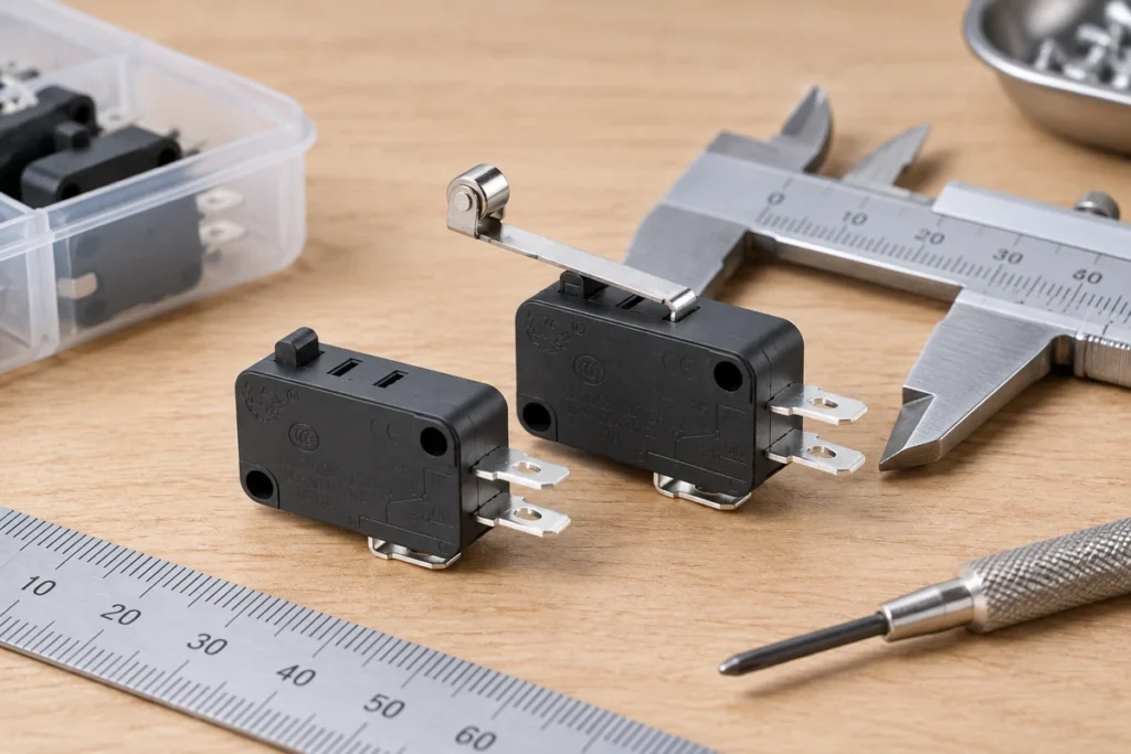
Micro Switch Operating Force: How to Match Force and Travel

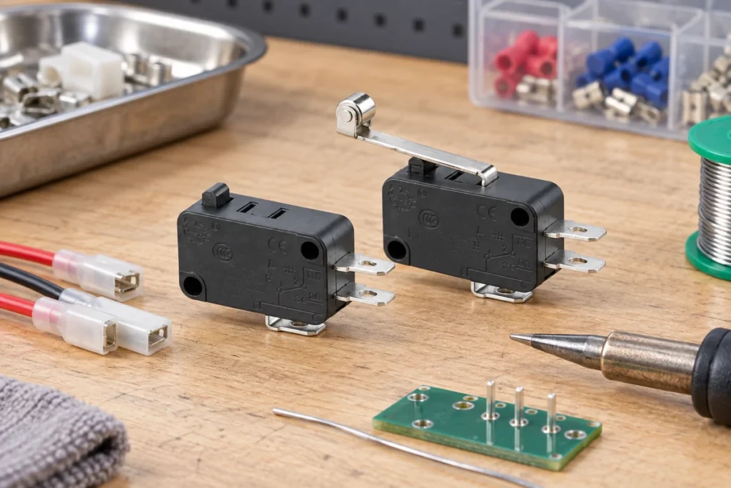
Micro switch operating force should be selected by matching the electrical function, mechanical interface, environment, and verification plan—not by copying a generic diagram or choosing from appearance alone. Operating force is the force needed to move the actuator to its operating point. It must be considered together with release force, pretravel, overtravel, actuator geometry, temperature, and manufacturing tolerance. A mechanism that only just reaches the nominal operating point can become intermittent as parts wear or dimensions stack up. This guide gives engineers and OEM buyers a practical way to define the requirement, compare samples, and avoid a part that works on the bench but fails after installation. Application-focused view using the matching LEMA product. What the term means in this application Operating force is the force needed to move the actuator to its operating point. It must be considered together with release force, pretravel, overtravel, actuator geometry, temperature, and manufacturing tolerance. A mechanism that only just reaches the nominal operating point can become intermittent as parts wear or dimensions stack up. The first job is to separate the switch's name from its required behavior. Product names are often shortened for search or purchasing, while an engineering drawing defines the contact state, terminal numbering, operating point, allowable travel, mounting reference, and ratings. If those details are missing, two parts with similar names may behave differently. Write the control requirement as a short sequence: the condition before actuation, the physical action that causes actuation, the electrical state after actuation, and the condition that resets it. This sequence prevents confusion between mechanical action and contact logic. It also gives the controls engineer, mechanical designer, buyer, and supplier one shared description to review. Do...

Read More
Electrical Control Box with Indicator Light: OEM Switch Selection Guide
Blog LEMA Electric

Electrical Control Box with Indicator Light: OEM Switch Selection Guide

electrical control box with indicator light oem became a priority because Google Search Console already shows real impressions for this topic on LEMA. That signal indicates an existing audience, but the previous site coverage did not fully match the question. This guide turns the query into a practical selection, integration and purchasing workflow for equipment designers, panel builders, maintenance teams and industrial buyers. An electrical control box with indicator lights combines command devices, visual status, enclosure protection, internal wiring and documentation. For an OEM build, begin with an operating narrative: every push button position, selector state and lamp condition must map to a defined machine state. Then specify lamp voltage, colour, legend, brightness, test function and behavior after loss of power. Keep indication honest—a green lamp should not imply that a hazardous condition is safe unless the control architecture proves it. The RFQ should include enclosure size and material, cutout drawings, wire labels, terminal blocks, incoming power, schematics, inspection records and applicable market requirements. Application view showing practical integration points for electrical control box with indicator light oem. What electrical control box with indicator light oem means in a real design A useful specification begins with behavior, not a catalogue photo. Write down what moves, what the operator or machine is trying to achieve, when the electrical state must change, and what should happen if a conductor opens or the device fails to reset. Separate the field device from the controller logic: a switch reports or commands a state, while the relay, PLC or control circuit decides how the machine responds. Similar product families often contain several contact arrangements, actuator styles, terminal forms and mounting versions. The family name helps...

Read More
Spring Pin Plunger Limit Switch Selection and Mounting Guide
Blog LEMA Electric

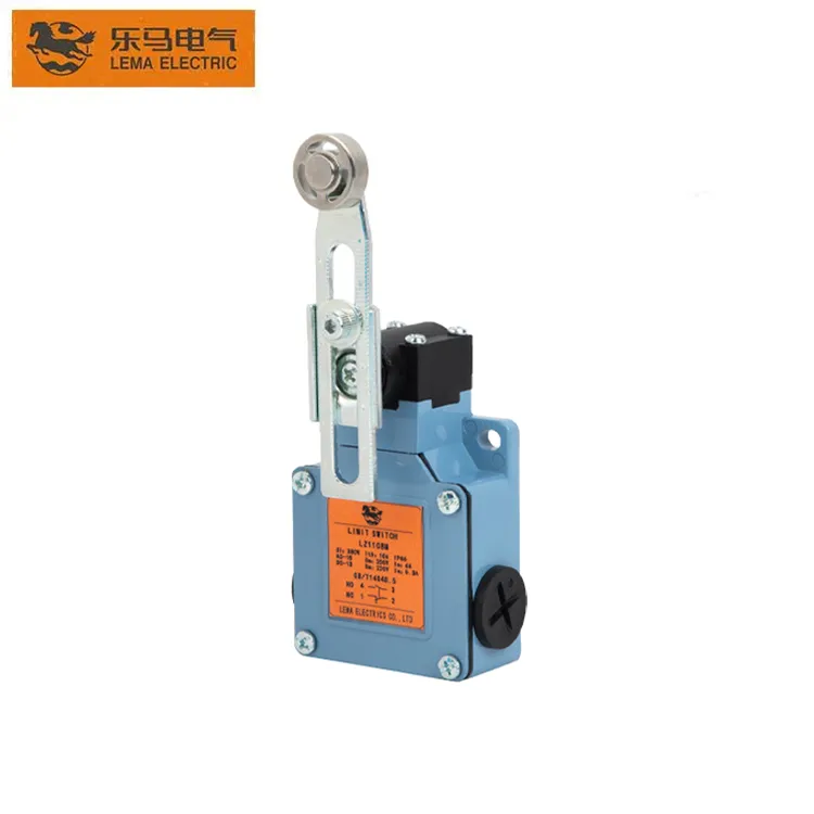
Spring Pin Plunger Limit Switch Selection and Mounting Guide

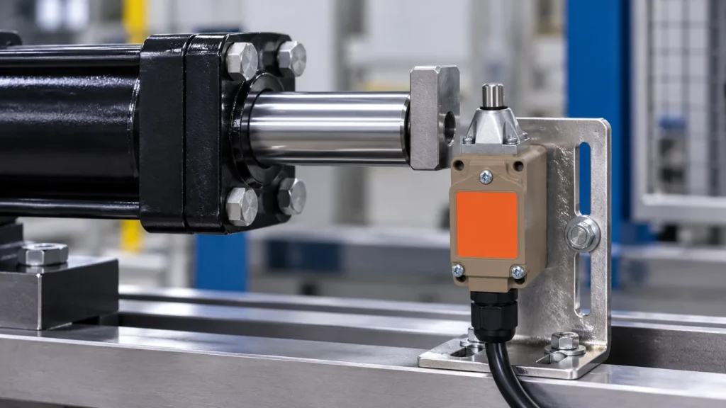
spring pin plunger limit switch became a priority because Google Search Console already shows real impressions for this topic on LEMA. That signal indicates an existing audience, but the previous site coverage did not fully match the question. This guide turns the query into a practical selection, integration and purchasing workflow for equipment designers, panel builders, maintenance teams and industrial buyers. A spring pin plunger limit switch is best for controlled, nearly axial contact. The machine target depresses the plunger until the internal contact changes state; the return spring resets the mechanism when the target leaves. A rigid direct plunger provides accurate position sensing but tolerates less lateral scraping than a roller or flexible actuator. The designer must control approach direction, target hardness and finish, operating travel, overtravel, release clearance and impact speed. If the target can arrive from an angle, redesign the cam surface or choose a roller-style actuator instead of forcing the pin sideways. Application view showing practical integration points for spring pin plunger limit switch. What spring pin plunger limit switch means in a real design A useful specification begins with behavior, not a catalogue photo. Write down what moves, what the operator or machine is trying to achieve, when the electrical state must change, and what should happen if a conductor opens or the device fails to reset. Separate the field device from the controller logic: a switch reports or commands a state, while the relay, PLC or control circuit decides how the machine responds. Similar product families often contain several contact arrangements, actuator styles, terminal forms and mounting versions. The family name helps discovery but does not define a production part. Use the complete model...

Read More
SPDT Switch Symbol, Terminal Logic and Schematic Guide
Blog LEMA Electric

SPDT Switch Symbol, Terminal Logic and Schematic Guide

spdt switch symbol became a priority because Google Search Console already shows real impressions for this topic on LEMA. That signal indicates an existing audience, but the previous site coverage did not fully match the question. This guide turns the query into a practical selection, integration and purchasing workflow for equipment designers, panel builders, maintenance teams and industrial buyers. The SPDT switch symbol shows one moving common contact that can connect to either of two stationary contacts. It describes electrical logic, not the physical view of a real switch. A schematic may show the normal or de-energized state according to its drafting convention, while the rear of a product can mirror what a front-view assumption suggests. Label the wires COM, NO and NC—or common, throw A and throw B—only after checking the manufacturer diagram and continuity. SPDT can select signals, reverse logic, provide alternate outputs or create an NO/NC pair for a controller input. Application view showing practical integration points for spdt switch symbol. What spdt switch symbol means in a real design A useful specification begins with behavior, not a catalogue photo. Write down what moves, what the operator or machine is trying to achieve, when the electrical state must change, and what should happen if a conductor opens or the device fails to reset. Separate the field device from the controller logic: a switch reports or commands a state, while the relay, PLC or control circuit decides how the machine responds. Similar product families often contain several contact arrangements, actuator styles, terminal forms and mounting versions. The family name helps discovery but does not define a production part. Use the complete model suffix, revision-controlled drawing and terminal diagram....

Read More
Toggle Switch Hole Size and Panel Mounting Guide
Blog LEMA Electric

Toggle Switch Hole Size and Panel Mounting Guide

toggle switch hole size became a priority because Google Search Console already shows real impressions for this topic on LEMA. That signal indicates an existing audience, but the previous site coverage did not fully match the question. This guide turns the query into a practical selection, integration and purchasing workflow for equipment designers, panel builders, maintenance teams and industrial buyers. Toggle switch hole size is not a universal number. The required opening follows the bushing diameter or snap-in body, anti-rotation feature, panel thickness, washer stack and permitted tolerance of the exact model. A nominal thread designation is not a finished cutout instruction. Use the supplier drawing, measure approved samples, and make a trial coupon in the real panel material and coating stack. Check rear clearance for terminals and wiring, lever clearance at every position, and tool access for the mounting nut. For sealed models, the hole edge and gasket compression are part of the ingress path. Application view showing practical integration points for toggle switch hole size. What toggle switch hole size means in a real design A useful specification begins with behavior, not a catalogue photo. Write down what moves, what the operator or machine is trying to achieve, when the electrical state must change, and what should happen if a conductor opens or the device fails to reset. Separate the field device from the controller logic: a switch reports or commands a state, while the relay, PLC or control circuit decides how the machine responds. Similar product families often contain several contact arrangements, actuator styles, terminal forms and mounting versions. The family name helps discovery but does not define a production part. Use the complete model suffix, revision-controlled...

Read More
Toggle Switch Mechanism: How It Works and How to Select One
Blog LEMA Electric

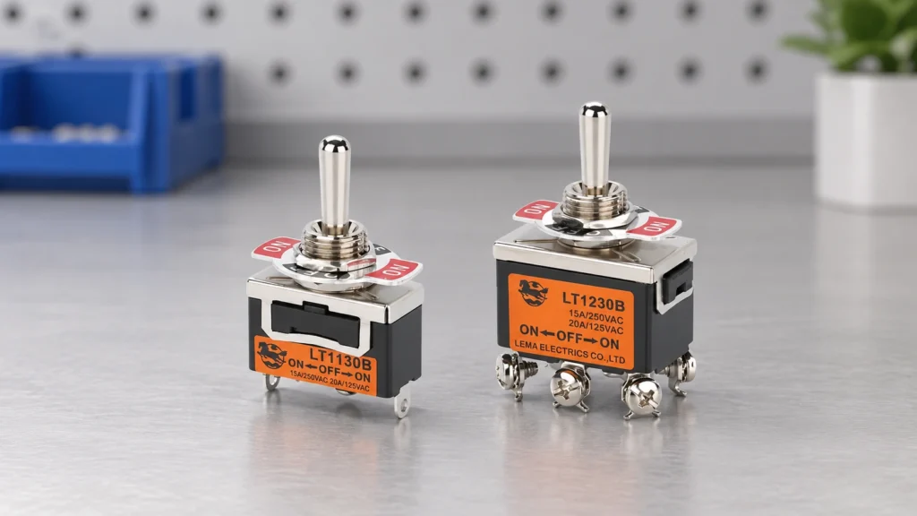
Toggle Switch Mechanism: How It Works and How to Select One

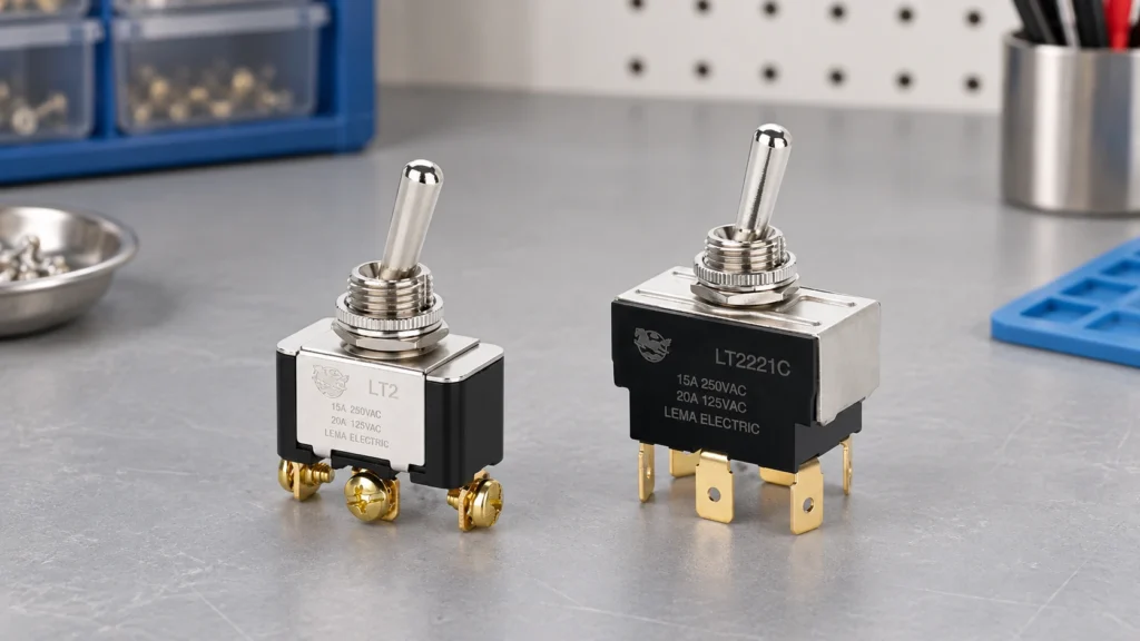
toggle switch mechanism became a priority because Google Search Console already shows real impressions for this topic on LEMA. That signal indicates an existing audience, but the previous site coverage did not fully match the question. This guide turns the query into a practical selection, integration and purchasing workflow for equipment designers, panel builders, maintenance teams and industrial buyers. A toggle switch mechanism uses the lever to move or snap internal contacts between stable or spring-return positions. The pole count tells how many separate circuits are controlled; the throw count tells how many paths each pole can select. ON-OFF, ON-ON and ON-OFF-ON labels describe stable positions, while parentheses or a specific datasheet notation may indicate momentary positions. The snap action can produce a quick electrical transition even when the operator moves the lever slowly. Selection must join the contact function to the actual panel geometry, load, environmental seal and human interface. Application view showing practical integration points for toggle switch mechanism. What toggle switch mechanism means in a real design A useful specification begins with behavior, not a catalogue photo. Write down what moves, what the operator or machine is trying to achieve, when the electrical state must change, and what should happen if a conductor opens or the device fails to reset. Separate the field device from the controller logic: a switch reports or commands a state, while the relay, PLC or control circuit decides how the machine responds. Similar product families often contain several contact arrangements, actuator styles, terminal forms and mounting versions. The family name helps discovery but does not define a production part. Use the complete model suffix, revision-controlled drawing and terminal diagram. If any selection...

Read More
Metal Push Button Switch: Durability, Panel Mounting and Selection Guide
Blog LEMA Electric

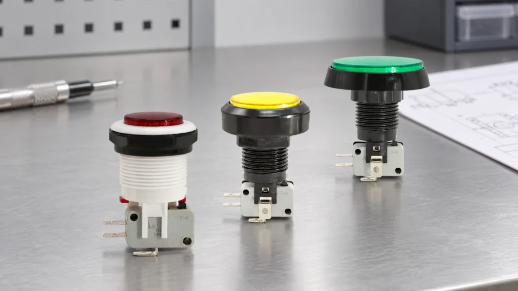
Metal Push Button Switch: Durability, Panel Mounting and Selection Guide

A metal push button switch puts a harder bezel and actuator on the panel face, but front-panel durability still depends on material grade, gasket torque, impact test scope, and whether the switch behind the head can survive over-travel. This guide contrasts metal and plastic bezels, separates anti-vandal marketing from IK proof, maps abuse paths that bypass a metal face, and shows what to freeze on drawings and samples before colour or LED options enter the RFQ. Product-focused view supporting metal push button switch selection and panel integration. ContentsWhat a metal push button switch actually protects on the panelMetal bezel vs plastic heads for daily panel abuseAnti-vandal marketing vs IK and seal proof buyers should demandPanel wear: gaskets, torque, and fixing mistakes that defeat a metal headAbuse paths that bypass a metal bezelDrawing and sample proof before you trust a metal operatorSelecting PBS Series options after metal and abuse requirements are documentedFAQsWhat a metal push button switch actually protects on the panel A metal push button switch is not a single material specification. In procurement language it usually means the visible bezel and actuator are metal—often a stainless steel push button or nickel-plated brass in public-facing designs—so finger impact, key scratches, and daily panel wear hit a harder surface than a light-duty plastic panel switch head. That front hardness is real, but it is bounded. The Bezel / actuator pair can still dent, spin in the hole, or leak behind the panel if the gasket stack, nut torque, or rear switch path is wrong. Treat “metal” as a front-abuse decision, not proof of IK impact class, ingress sealing, or internal contact life. On a self-service kiosk, the metal ring is what...

Read More
Industrial Push Button Switch Selection: Environment, Duty and OEM Guide
Blog LEMA Electric

Industrial Push Button Switch Selection: Environment, Duty and OEM Guide

An industrial push button switch matches the panel zone first: dust, moisture, temperature swings, and vibration set the sealing and mounting stress before you compare actuators on a control panel. This article walks environment classification, mechanical cycle duty, electrical contact logic, LED illumination options, colour codes, and RFQ fields that keep procurement aligned with real machine conditions. Product-focused view supporting industrial push button switch selection and panel integration. ContentsHow Dust and Moisture Change Push Button SelectionTemperature Swings and Vibration at the Panel EdgeMechanical Cycle Duty: Matching Press Frequency to Switch LifeElectrical Interface Questions Before You Lock a Part NumberColour Codes and LED Options for Operator ClarityOEM RFQ Fields That Prevent Wrong-Spec DeliveriesSelect a PBS Industrial Push Button for Your Panel JobFAQHow Dust and Moisture Change Push Button Selection Dust and moisture decide whether a panel mount push button switch survives at the cutout, not just behind the bezel. Every hole is an ingress path, and IP rating thinking should follow the wettest zone on the control panel. Community builders note that adding buttons to a certified enclosure can change how the whole door performs against dust and spray. Important: Forum makers report that splashing water can press a tact switch unintentionally — wet zones need an actuator sealing plan, not only a higher IP label on a catalog line. Panel zone signal What to document in RFQ Why it matters for selection Dry indoor cabinet Dust class, occasional wipe-down Sealing focus on bezel gap and cable entry Humid or wash-adjacent Spray direction, chemical exposure Panel hole and actuator seal become primary Mixed door (display + buttons) Which functions sit in wettest area Example industrial operator families cite IP65 for dust...

Read More
SPDT KW10 Limit Micro Switch: Terminals, Actuation and Selection
Blog LEMA Electric

SPDT KW10 Limit Micro Switch: Terminals, Actuation and Selection

spdt kw10 limit micro switch became a priority because Google Search Console already shows real impressions for this topic on LEMA. That signal indicates an existing audience, but the previous site coverage did not fully match the question. This guide turns the query into a practical selection, integration and purchasing workflow for equipment designers, panel builders, maintenance teams and industrial buyers. A KW10-style SPDT micro switch normally exposes COM, NO and NC terminals. In the released state COM is connected to one throw; after actuation the snap mechanism transfers COM to the other. The family name does not guarantee identical terminal orientation, actuator force, life or electrical rating across suppliers and suffixes. Trace the markings on the exact component, confirm both states with an unpowered continuity test, and align the actuator so the target supplies adequate operating travel without crushing the plunger. Use the changeover contact to obtain the controller logic you need rather than assuming NO is always the preferred choice. Application view showing practical integration points for spdt kw10 limit micro switch. What spdt kw10 limit micro switch means in a real design A useful specification begins with behavior, not a catalogue photo. Write down what moves, what the operator or machine is trying to achieve, when the electrical state must change, and what should happen if a conductor opens or the device fails to reset. Separate the field device from the controller logic: a switch reports or commands a state, while the relay, PLC or control circuit decides how the machine responds. Similar product families often contain several contact arrangements, actuator styles, terminal forms and mounting versions. The family name helps discovery but does not define a...

Read More
Ultra Miniature Micro Switch Selection and Integration Guide
Blog LEMA Electric

Ultra Miniature Micro Switch Selection and Integration Guide

ultra miniature micro switch became a priority because Google Search Console already shows real impressions for this topic on LEMA. That signal indicates an existing audience, but the previous site coverage did not fully match the question. This guide turns the query into a practical selection, integration and purchasing workflow for equipment designers, panel builders, maintenance teams and industrial buyers. An ultra miniature micro switch saves volume only when its actuator, terminals and tolerance chain are designed together. Small housings usually leave less room for misalignment, soldering heat, board flex and excessive overtravel. Select the actuator by the motion presented by the product: a direct plunger suits controlled linear travel, while a lever can reduce operating force and absorb some approach variation. PCB models require special attention to hole pattern, seating, solder profile, cleaning process and mechanical support. The PCB should not become the stop that absorbs external impact. Application view showing practical integration points for ultra miniature micro switch. What ultra miniature micro switch means in a real design A useful specification begins with behavior, not a catalogue photo. Write down what moves, what the operator or machine is trying to achieve, when the electrical state must change, and what should happen if a conductor opens or the device fails to reset. Separate the field device from the controller logic: a switch reports or commands a state, while the relay, PLC or control circuit decides how the machine responds. Similar product families often contain several contact arrangements, actuator styles, terminal forms and mounting versions. The family name helps discovery but does not define a production part. Use the complete model suffix, revision-controlled drawing and terminal diagram. If any selection...

Read More
Push Button Colour Standards for Industrial Control Panels
Blog LEMA Electric

Push Button Colour Standards for Industrial Control Panels

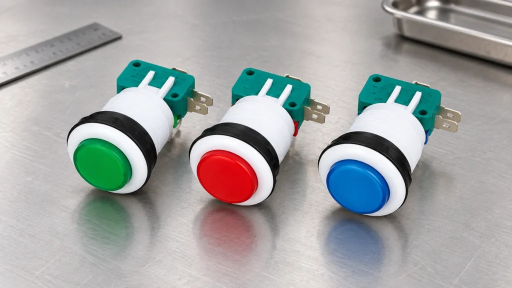
push button colour standards became a priority because Google Search Console already shows real impressions for this topic on LEMA. That signal indicates an existing audience, but the previous site coverage did not fully match the question. This guide turns the query into a practical selection, integration and purchasing workflow for equipment designers, panel builders, maintenance teams and industrial buyers. Push-button colour communicates expected action, but colour alone must never carry the entire meaning. A control panel should combine colour with a durable text label, symbol, position and consistent operating sequence. Red is commonly reserved for emergency or stop-related functions, green is commonly associated with starting or a normal condition, and yellow often signals an abnormal condition or intervention. The exact assignment depends on the applicable machine and market standards. Designers should document the selected convention, review local requirements, and prevent illuminated buttons from creating contradictory messages when lit and unlit. Application view showing practical integration points for push button colour standards. What push button colour standards means in a real design A useful specification begins with behavior, not a catalogue photo. Write down what moves, what the operator or machine is trying to achieve, when the electrical state must change, and what should happen if a conductor opens or the device fails to reset. Separate the field device from the controller logic: a switch reports or commands a state, while the relay, PLC or control circuit decides how the machine responds. Similar product families often contain several contact arrangements, actuator styles, terminal forms and mounting versions. The family name helps discovery but does not define a production part. Use the complete model suffix, revision-controlled drawing and terminal diagram. If...

Read More
Cam Limit Switch Working Principle, Setup and Selection Guide
Blog LEMA Electric

Cam Limit Switch Working Principle, Setup and Selection Guide

cam limit switch working principle became a priority because Google Search Console already shows real impressions for this topic on LEMA. That signal indicates an existing audience, but the previous site coverage did not fully match the question. This guide turns the query into a practical selection, integration and purchasing workflow for equipment designers, panel builders, maintenance teams and industrial buyers. A cam limit switch converts the angular position of a shaft or machine cycle into one or more electrical state changes. A rotating cam profile reaches an actuator at a chosen angle; the internal snap-action contact then changes state. The useful result is not simply “the cam touched the switch.” It is a repeatable switching window with adequate approach, overtravel and release margin. Setup therefore begins with the machine sequence: identify the earliest and latest acceptable switching angles, account for backlash and stopping distance, and make adjustments at reduced speed. Never use the switch body as the mechanical end stop. Application view showing practical integration points for cam limit switch working principle. What cam limit switch working principle means in a real design A useful specification begins with behavior, not a catalogue photo. Write down what moves, what the operator or machine is trying to achieve, when the electrical state must change, and what should happen if a conductor opens or the device fails to reset. Separate the field device from the controller logic: a switch reports or commands a state, while the relay, PLC or control circuit decides how the machine responds. Similar product families often contain several contact arrangements, actuator styles, terminal forms and mounting versions. The family name helps discovery but does not define a production...

Read More