CENTRO DE NOTICIAS LEMA

Noticias y Blog

Centro de noticias

Micro Switch Lot Traceability: Link Delivered Parts to OEM Records
Blog LEMA Electric

Micro Switch Lot Traceability: Link Delivered Parts to OEM Records

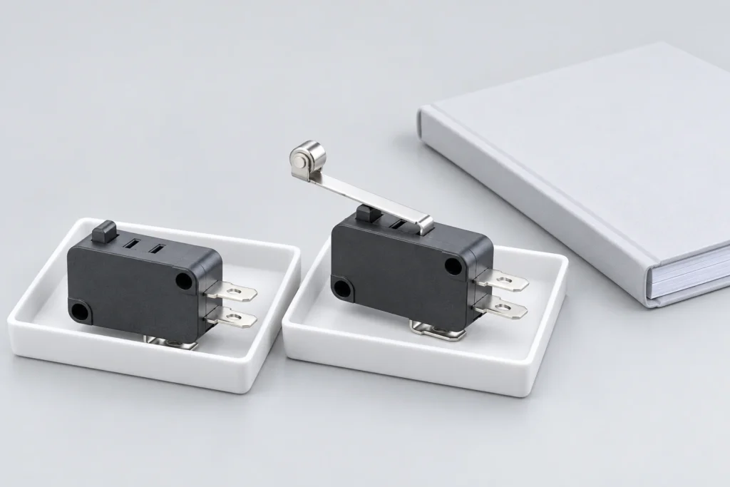
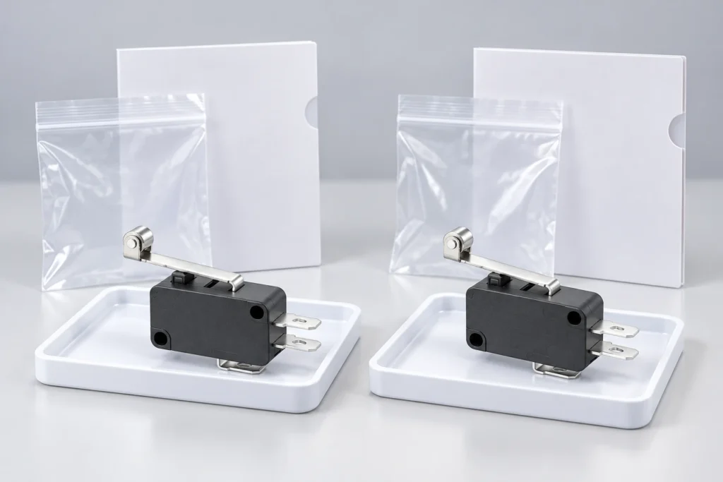
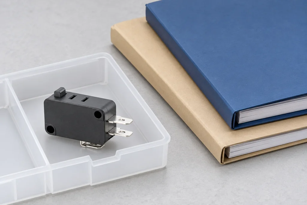
Micro switch lot traceability connects the component received by an OEM to its purchase specification, supplier lot, inspection decision and eventual assembly use. A readable bag label alone is insufficient: the relationship must survive repacking, partial issues, returns and work in progress. Start with the complete ordered part identity, preserve the supplier's actual lot information, and record every event that changes custody or disposition. Traceability supports investigation and containment; it does not prove that an untested switch is conforming or that every unit in a lot has identical performance. Define what must be traced before requesting labels For a Lemaele KW7 product inquiry, separate the family name from the exact configuration requested. Actuator form, terminal arrangement and the applicable controlled drawing belong in the purchasing record when they affect the assembly. A generic family description should not silently stand in for the agreed variant. Ask what identifiers the supplier actually provides and what each identifies. A date code may represent production time, packaging time or another event; its meaning needs confirmation rather than visual guesswork. Specify the investigation question that the records must answer. One OEM may need to locate unused material from a suspect shipment; another may need to identify assemblies containing a particular supplier lot. Those questions require different event records. Agree the needed level before delivery, including whether tracing is by supplier lot, package, internal batch or individual unit. Do not require serial numbers merely because a software system has a serial-number field. An identifier is useful only when its relationship to the physical material remains controlled. Separate KW7 specimens in individual trays beside blank identity cards. Product-reference illustration; separate objects are not an approved installation or...

Leer más
Plunger Limit Switch Side Loading: Diagnose Alignment and Guide the Target
Blog LEMA Electric

Plunger Limit Switch Side Loading: Diagnose Alignment and Guide the Target

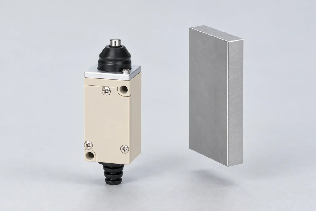
Plunger limit switch side loading occurs when the target or surrounding mechanism applies a transverse load instead of the intended motion along the actuator's permitted direction. It can arise from an angled approach, misalignment, a rubbing target, bracket movement or an inadequately guided part. Diagnose the complete interface before replacing the switch. A larger-looking housing or a deeper actuation setting does not automatically make an unsuitable approach acceptable. The LEMA HL compact limit-switch family supplies the bare-plunger reference used in the figures. The loose guide and target specimens are explanatory objects, not an approved fixture. This guide provides no universal side-force allowance, approach angle or travel limit; use the exact model drawing and manufacturer guidance. Identify the intended direction of actuation Start with the controlled actuator drawing. Identify the motion direction, contact surface, reference point and allowed working travel. Do not infer those details from a catalogue photograph alone. A plain plunger and a roller or lever actuator can require different target arrangements. The plunger selection guide addresses the wider selection context. This article focuses on identifying and removing unintended transverse loading in the machine-side interface. Record the installed orientation and the complete target path. A target can approach correctly at one position but move sideways relative to the plunger as the mechanism rotates, flexes or reverses. Review the movement that actually occurs rather than only the nominal centerline on a sketch. Separate side loading from excessive travel Side loading concerns force direction and contact geometry. Excessive travel concerns how far the actuator is driven. Both can occur together, but they are not the same problem and a correction for one may leave the other unresolved. Measure the relevant positions...

Leer más
Toggle Switch Low-Level Signals: Review Dry-Circuit Compatibility
Blog LEMA Electric

Toggle Switch Low-Level Signals: Review Dry-Circuit Compatibility

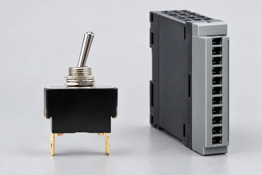
A toggle switch used for a low-level signal needs evidence for the actual electronic input, not only a high-current power rating. The input voltage and current, contact behavior, permitted signal errors, environment and operating sequence must all be considered. An ordinary continuity beeper can identify a static path but cannot establish reliable service on every dry-circuit or low-current interface. Ask for applicable minimum-load information and validate the complete selector circuit before release. The LEMA LT2210C product is the visible toggle reference in this article. Its appearance or headline power rating does not establish a low-level switching guarantee. The disconnected instruments in the figures illustrate review boundaries, not a tested circuit, recommended pinout or model-specific dry-circuit approval. Define what low level means in the actual circuit Describe the signal source and receiver. Record the input voltage, current through the closed contact, thresholds, leakage paths, wiring and the intended response. A logic input, resistive sensing network and analogue measurement path can impose different requirements even when their nominal supply is similar. Avoid treating “dry circuit” as a universal voltage or current limit. Terminology and test conditions need to be understood in the relevant specification. State the actual values and acceptance criteria for the equipment instead of relying on an undefined label. The NIST guidance on electric current provides the unit basis. Keep ampere, milliampere and microampere values distinct when preparing the review; a unit mistake can conceal how little current an electronic input actually supplies. Separate maximum load capacity from minimum-load suitability A power rating addresses operation under stated load conditions. It does not automatically answer whether the contact will provide the required behavior at a much smaller signal level. Likewise, a...

Leer más
Micro Switch Sample Approval: Build an OEM Qualification Record
Blog LEMA Electric

Micro Switch Sample Approval: Build an OEM Qualification Record

Micro switch sample approval should establish whether an identified component and assembly meet a defined OEM requirement. It is not simply a request for a few parts that look similar to an existing switch. Freeze the intended function, interfaces, circuit and operating conditions, identify the submitted samples, and agree the evidence needed before making a release decision. A successful hand-operated continuity check is a useful observation, not a complete design qualification. The LEMA KW7 family provides the product reference for organizing actuator, terminal and force options. The samples pictured here are illustrative specimens, not certified approval samples or evidence of a completed OEM qualification. Use the exact proposed order code and current controlled documents. Begin with the requirement the sample must answer Write down the equipment function and the reason for evaluating the candidate. Is it a new design, a form-and-fit alternative, a different actuator or an interface to a particular controller input? A sample plan should answer that decision rather than collect measurements without a purpose. Identify the required contact function, electrical duty, mounting references, available travel, force constraints, environmental exposure and expected operating sequence. Mark unknown fields explicitly. Do not let a sample's convenient availability silently define the final equipment requirement. The custom OEM inquiry guide supports the initial communication. Sample approval turns that inquiry into a controlled comparison between the stated requirement and the actual submitted configuration. Freeze the candidate identity before testing Record the full order code, drawing revision, actuator, terminal type, contact arrangement and relevant rating option. Link the samples to the supplier's submission and any available lot or production identification. A family name alone is insufficient when several visible or internal variants can exist....

Leer más
Micro Switch Roller Wear: Inspect the Target Interface Before Replacement
Blog LEMA Electric

Micro Switch Roller Wear: Inspect the Target Interface Before Replacement

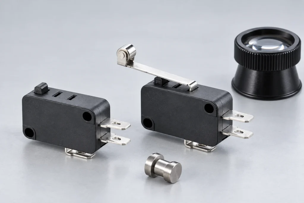
Micro switch roller wear should be inspected as a problem at the complete target interface, not judged from a noisy input alone. Examine the roller, its support, the lever, the cam surface and their relative movement. Record the original condition before cleaning or adjusting anything. A worn target, a loose bracket or an unsuitable approach can produce symptoms that resemble a worn switch roller, and fitting another switch without correcting that cause may repeat the problem. The LEMA KW7 product family includes the roller-lever form used in these illustrations. The pictured specimens are intact reference products; they are not evidence of a failed unit or a claim about a universal wear limit. Obtain the drawing and permitted operating conditions for the exact actuator variant. Define the symptom before naming the worn part Describe what the equipment actually did. Examples include a changing trigger position, a rough mechanical feel, an intermittent input or a target that no longer clears the lever. Record when the symptom occurs and whether it follows a particular direction, speed or portion of the machine cycle. Do not diagnose roller wear solely from an electrical trace. Contact behavior, wiring, input filtering and target movement can produce similar reports. Compare the mechanical observation with the isolated electrical state and the controller indication. The micro switch failure-mode guide provides the wider fault-boundary framework; this article focuses on the roller and the surface that drives it. Keep the original adjustment intact until it is documented. An immediate position change can make the machine run again while hiding the evidence needed to understand the wear process. Isolate the mechanism and preserve the original condition Follow the equipment's energy-control procedure before inspecting...

Leer más
Micro Switch Transport Packaging: Protect Actuators, Terminals and Identity
Blog LEMA Electric

Micro Switch Transport Packaging: Protect Actuators, Terminals and Identity

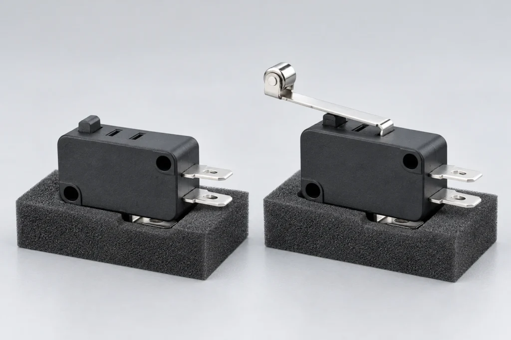
Micro switch transport packaging should protect the housing, actuator, terminals and part identity throughout the intended shipping route. A strong outer carton alone cannot prevent a lever from being pressed by neighboring parts or a terminal from taking load inside a loose bag. Define how each component is supported, separated and identified, then evaluate the complete package under an appropriate distribution test plan. Do not treat the switch's own shock rating as proof that any shipping arrangement is acceptable. The LEMA KW7 family supplies the real product reference used here. The illustrated foam and cartons are planning examples, not a qualified package specification, a claim about an existing shipping process or evidence of a passed transit test. Map the product features that need protection Identify the parts most vulnerable to unintended contact: the actuator or lever, roller support, exposed terminals, mounting features and markings. Record the permitted handling conditions from the component documentation. A packaging review should distinguish a robust body surface from a functional feature that should not carry shipping load. Include the exact variant. A bare plunger, long lever and roller lever can require different clearances even when the housing dimensions are similar. A tray designed around one actuator should not automatically be approved for the whole product family. The actuator-selection guide provides background for those differences. Use the actual approved drawing and sample when defining compartment dimensions and the contact surfaces of a support. Support the housing without holding the actuator operated Locate the component on surfaces approved for handling and avoid pressing a lever, plunger or terminal into the packaging material. Provide clearance above the actuator and around its intended movement envelope. A package that looks...

Leer más
Micro Switch Cleaning Solvents: Qualify the Process Before Exposure
Blog LEMA Electric

Micro Switch Cleaning Solvents: Qualify the Process Before Exposure

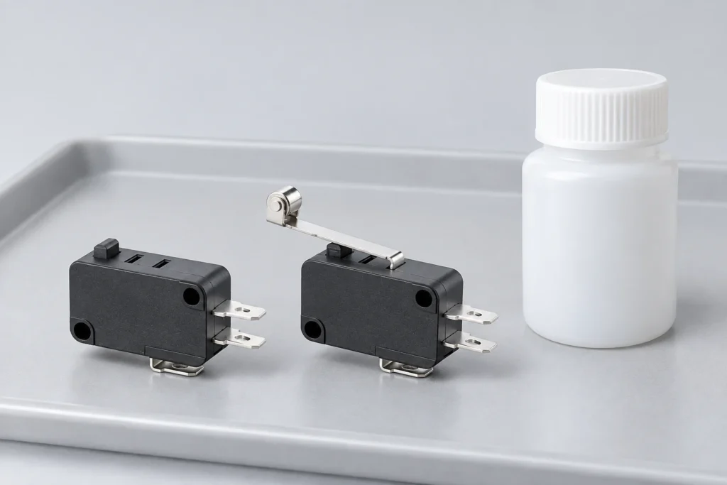
Micro switch cleaning solvents must be assessed for the exact switch, surrounding materials and cleaning process before exposure. A cleaner that removes visible contamination is not automatically compatible with the housing, actuator, seals, markings, lubricant or contact system. Nor does a water-protection description establish resistance to a chemical bath, spray or ultrasonic process. Obtain the manufacturer's supported conditions and qualify the complete assembly instead of trying an unspecified solvent on production parts. The LEMA KW7 family is the visible product reference in this guide. The closed bottle and dry specimens in the figures illustrate process review only. They do not identify an approved cleaner, demonstrate a cleaning result or claim that the illustrated variant is sealed against chemical entry. Define why cleaning is being proposed Identify the contamination and the reason it must be removed. Flux residue, machining debris, oil, handling contamination and an external cosmetic mark are different problems. Record where the material is located and whether the proposed process can move it toward an opening or contact system. Also ask whether cleaning can be avoided by controlling the earlier process. A protective cover during assembly, cleaner handling or a revised material application may prevent contamination more reliably than a later cleaning operation. Such a change still needs review, but it can remove an unnecessary exposure. Do not clean a failure-analysis specimen before its condition is recorded. The failure-mode guide explains why preserving original evidence matters. A cleaned suspect part cannot reveal every feature of the original contamination event. Identify every material and interface at risk Review the housing, actuator, seals where present, terminal region, markings, adhesives and adjacent assembly parts. A chemical may affect one material while leaving...

Leer más
Notificación de cambio de proveedor: revisión y recalificación de una pieza original del fabricante
Blog LEMA Electric

Notificación de cambio de proveedor: revisión y recalificación de una pieza original del fabricante

A switch supplier change notification should identify what is changing, which part numbers and lots are affected, when the change will occur and what evidence supports continued use. An OEM should assess the effect on its approved assembly before accepting the revised supply. A change that leaves the external dimensions unchanged can still affect materials, contact behavior, manufacturing controls, approvals or traceability. Treat the notification as a controlled engineering decision, not simply an update to a purchasing description. The LEMA KW7 family provides a real product reference for organizing model and variant information. This article describes an OEM review process; it does not announce an actual LEMA change, claim a specific notice period or assert that an illustrated specimen represents a revised production lot. Establish the approved baseline Collect the current order code, controlled drawing, relevant specification, approved sample record and equipment bill of materials. Identify the actuator, contact form, terminal type, rating option and other variant fields that matter to the application. The baseline should describe the accepted configuration rather than a generic family name. A purchasing system that records only “micro switch” cannot reliably distinguish variants or determine which equipment is affected by a change. Resolve incomplete records before comparing the proposal. The custom micro-switch RFQ guide addresses initial requirement communication. Change review begins later, with an already approved configuration and the obligation to understand the effect of a proposed difference. Ask what is changing and why The notification should identify the actual change boundary. Examples include a material, contact finish, tooling, manufacturing location, process, subcontractor, test method, marking or packaging. These examples are review categories, not statements that such a change has occurred at LEMA. Ask for...

Leer más
Inspección rápida de desconexión mediante crimpado: evidencia de cable, terminal y herramienta
Blog LEMA Electric

Inspección rápida de desconexión mediante crimpado: evidencia de cable, terminal y herramienta

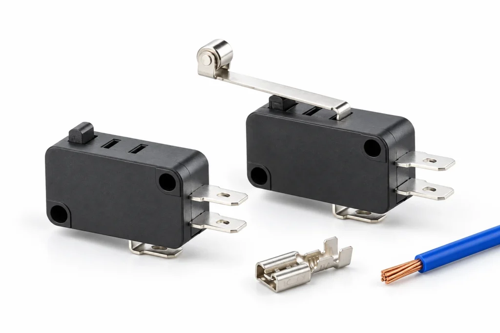
Quick-disconnect crimp inspection should evaluate the wire-to-receptacle joint separately from the receptacle's fit on the switch tab. Confirm the exact wire, terminal, tooling and process, then inspect the conductor crimp, insulation support and completed assembly against the approved criteria. A terminal that slides onto a switch blade does not prove the wire crimp is sound. Equally, a good wire crimp cannot approve a mismatched receptacle or an excessive force applied to the switch terminal. The LEMA KW7 family provides the visible switch reference in this article. The loose receptacles and wire specimens are explanatory objects, not a claim that a particular crimp terminal, wire size or tool has been approved for every KW7 variant. Use the selected terminal manufacturer's controlled application specification. Identify the connection being inspected A quick-disconnect assembly contains several interfaces: wire strands to the crimp barrel, insulation to its support feature, receptacle to switch blade, and harness support to the surrounding equipment. Define which interface the inspection or test is evaluating. A loose wire, a loose receptacle and a loose switch blade are not interchangeable findings. Record exactly where movement occurs. The switch-terminal types guide explains the broader terminal options, while the terminal-strength article addresses loads at the switch itself. Do not use the switch as a convenient anchor for testing a wire crimp. A pull applied through the blade can damage the switch or combine several failure modes into an uninterpretable result. The approved test method should define the specimen boundary and fixture. Match wire, terminal and tooling before inspection Record the terminal part number, wire construction, conductor size, insulation dimensions and stripping requirements. Identify the specified crimp tool, die or applicator and the relevant setup....

Leer más
Retención del conector IEC: Compruebe la compatibilidad de la conexión y la extracción del cable por separado
Blog LEMA Electric

Retención del conector IEC: Compruebe la compatibilidad de la conexión y la extracción del cable por separado

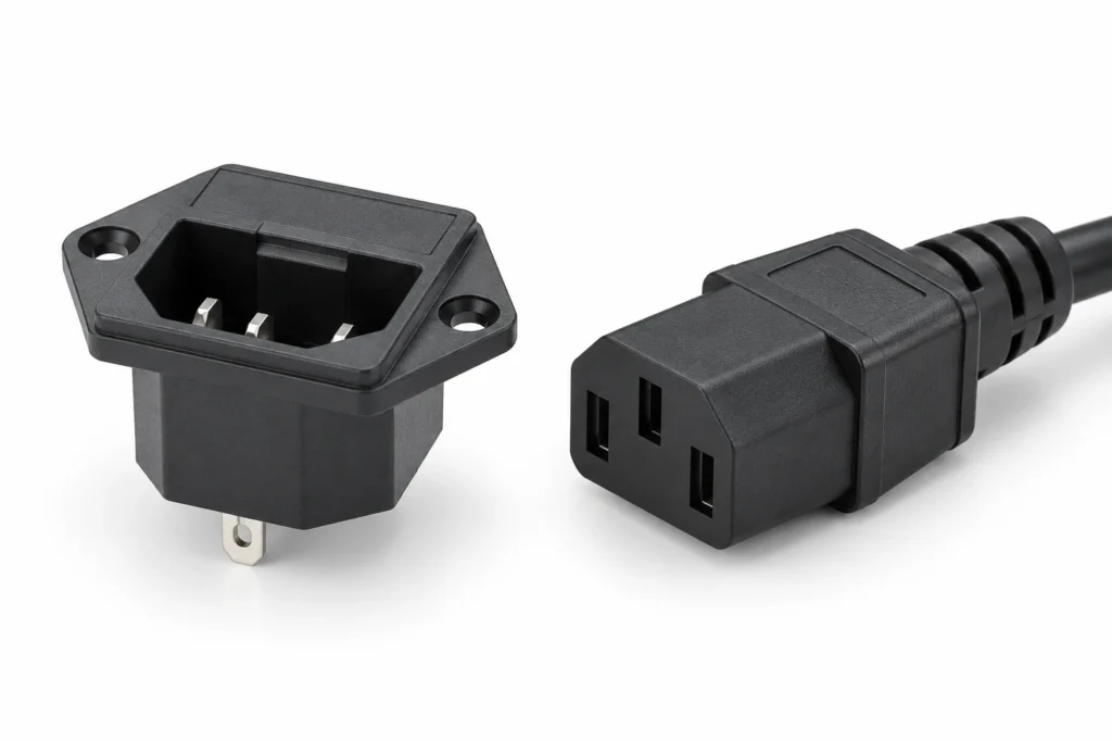
IEC connector retention is the resistance of a mated equipment connector to unintended separation under the specified conditions. It is different from the force that holds an inlet in a panel and from the strain relief that holds a cable in its connector body. Check those boundaries separately. A connector that is hard to insert is not automatically safe, correctly matched or electrically sound, and a locking accessory cannot be assumed to fit a standard inlet without model-specific evidence. This guide uses the LEMA IPZ equipment-inlet family as a visible product reference. It does not assign a retention-force value to the family, certify a mating cable assembly or illustrate an unverified locking mechanism. Obtain the exact inlet, connector and equipment requirements before defining an acceptance test. Identify the three mechanical boundaries First, the mating connector has to engage the equipment inlet in the intended way. Second, the inlet has to remain securely mounted in the panel. Third, the cable has to remain properly retained within its own connector or assembly. A failure at any one boundary can look like a “loose power socket” to an operator. Record which parts move during the reported event. Does the cable connector withdraw while the inlet stays still, does the inlet move in the panel, or does the cable move relative to its connector housing? Preserve that distinction in the inspection record. Increasing panel clamp force cannot repair a worn mating interface, and stronger cable strain relief cannot establish correct connector compatibility. Confirm the exact mating combination Identify the inlet and connector by their complete designations, ratings and approved cable assembly. Similar-looking parts can differ in temperature class, current rating, geometry or intended use....

Leer más
Estabilidad de montaje del interruptor de pie: Evita que se deslice, balancee y se tire el cable
Blog LEMA Electric

Estabilidad de montaje del interruptor de pie: Evita que se deslice, balancee y se tire el cable

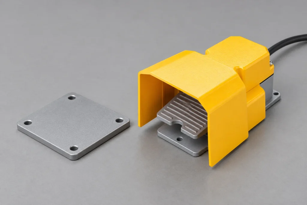
Foot switch mounting stability means that the pedal remains in its intended position and orientation during normal operation, release and cable movement. A pedal can have a comfortable operating force yet still slide, rock or rotate on the actual floor. Review the base, support surface, cable forces, footwear, operator position and permitted mounting method together. Do not assume that a heavy housing or a textured tread proves adequate stability in every work area. The LEMA LF foot-switch family is the product reference used here. The figures show the visible guarded pedal and separate installation specimens; they do not claim a slip-resistance rating, add unapproved mounting holes or qualify an operator-presence safety function. Define what must remain stable Record the intended pedal location and the range of acceptable movement. Consider translation across the floor, rotation, rocking and lifting. These are different behaviors and may have different causes. A pedal that stays approximately in the same area can still rotate enough to change the operator's approach. Define the operation sequence: single actuation, repeated commands, extended hold or deliberate release. Include the position of the operator and the required machine response. Stability matters through the complete sequence, not only when the pedal is first placed on a clean bench. The pedal-force and ergonomics guide addresses the force and human-interface questions. The present review concerns how the complete pedal base remains supported while that force is applied. Inspect the base and support surface Check whether the pedal sits on its intended support points without rocking. Look for damage, missing feet, loose hardware, uneven contact or an obstruction beneath the base. Do not correct rocking by adding an improvised packing piece that can move or...

Leer más
Nut de montaje del interruptor de conmutación: comprobaciones de ajuste y rotación
Blog LEMA Electric

Nut de montaje del interruptor de conmutación: comprobaciones de ajuste y rotación

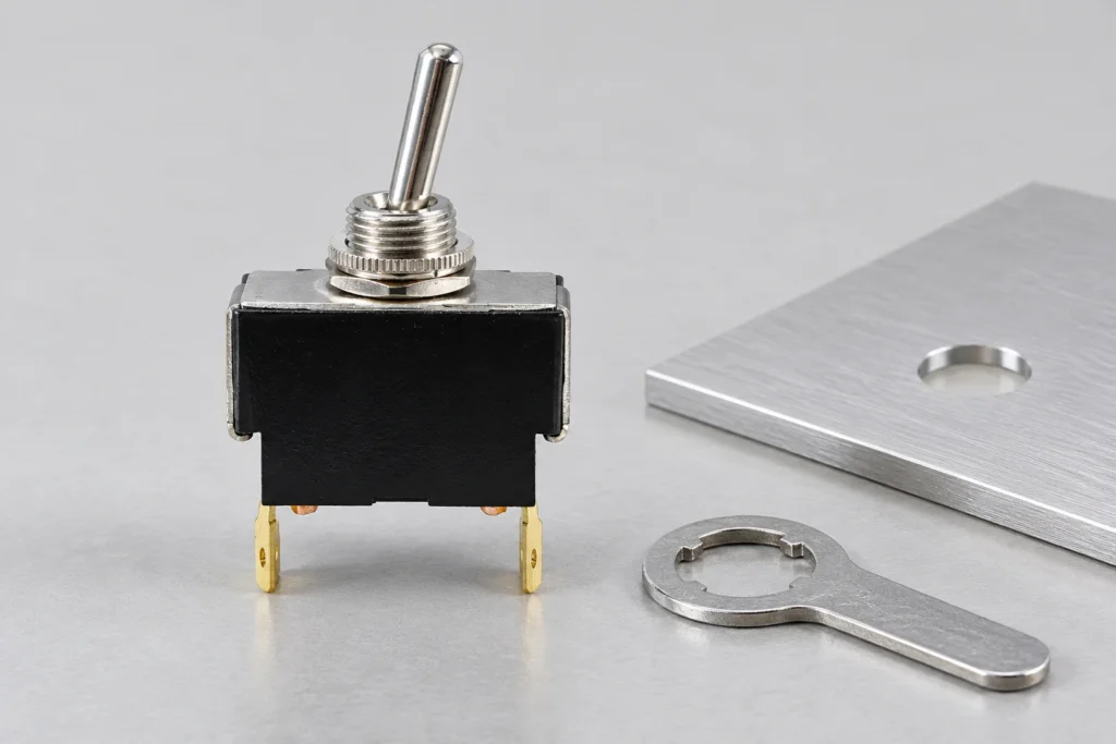
A toggle switch mounting nut clamps the switch's threaded bushing and hardware stack to the panel. A secure installation needs more than a nut that feels tight: the bushing, panel thickness, washers, thread engagement, tool access and resistance to rotation all have to match the exact model drawing. Use the manufacturer's specified tightening method and torque where provided. Do not transfer a torque value from another switch or keep tightening until the panel, seal or switch body deforms. This guide concerns mechanical retention of a threaded-bushing toggle. The LEMA LT2210C product provides the visible product reference. The illustrations preserve its existing bushing, nut and washer; they do not add an unverified anti-rotation accessory or claim that a particular tool setting has been approved. Identify the complete clamp stack List the components between the switch body and the outer nut: panel, flat washers, sealing parts, locating hardware and any other manufacturer-approved pieces. Record their order and orientation from the controlled drawing. A stack assembled from visually similar spare hardware may not behave like the original. Check that the panel is within the permitted thickness range. Added paint, an overlay, a gasket or a second backing plate can consume the available bushing length. The nut must engage as specified without bottoming on an unintended feature or leaving an unsupported stack. The panel cutout guide addresses hole geometry and clearance. Nut tightening is the next question: whether the actual stack can establish and maintain the required clamp without damaging the component or panel. Verify thread and hardware identity A nut that starts onto a thread is not automatically the correct hardware. Confirm the thread form and the approved nut and washer part numbers....

Leer más