CENTRO DE NOTICIAS LEMA

Noticias y Blog

Centro de noticias

Power Socket Failure Modes: Loose Contacts, Heat and Arcing
Blog LEMA Electric

Power Socket Failure Modes: Loose Contacts, Heat and Arcing

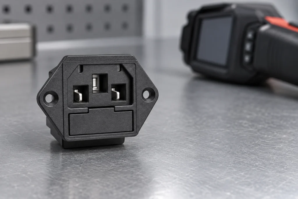
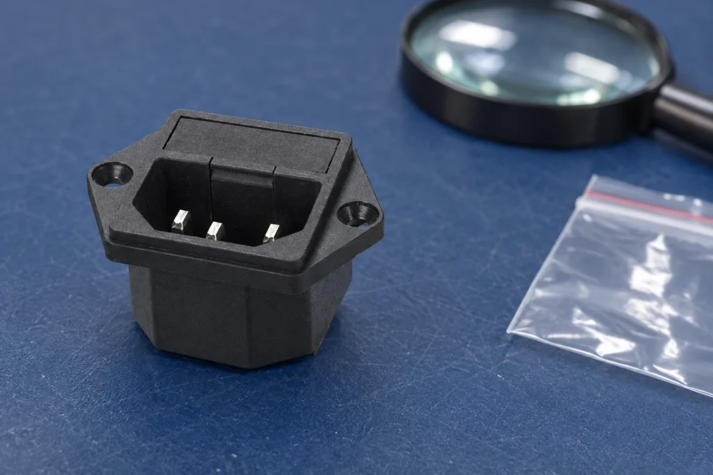
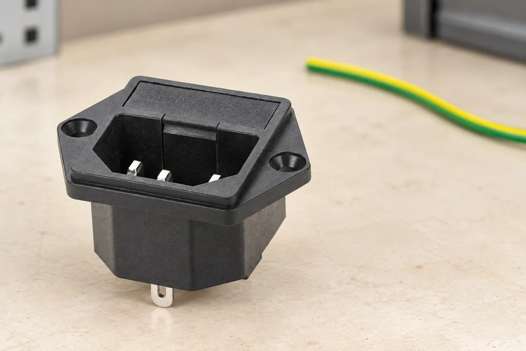
Power socket failure modes in equipment include a damaged mating interface, loose or unsuitable terminations, inadequate mechanical retention, contamination and deterioration associated with heat or electrical discharge. A darkened housing is evidence to investigate, not a diagnosis by itself. Remove affected equipment from use under its approved isolation procedure and preserve the inlet, mating connector and connection records before replacing parts. This guide concerns panel-mounted equipment power inlets such as the LEMA IPZ family, not household receptacle repair. Qualified personnel must establish the complete fault and validate the correction; reconnecting a damaged inlet to see whether it works is not an acceptable investigation method. Define which part of the power interface failed An equipment power interface includes the supply cord, mating connector, inlet contacts, housing, mounting and internal terminations. Some arrangements also contain a fuse drawer, switch or other component. The observed symptom may arise at any of those boundaries. Record the exact configuration and component order codes before calling every failure a socket fault. A replacement inlet cannot correct a defective cord connector or an incorrectly assembled internal termination. Separate loss of power, intermittent operation and visible damage as observations. A device that stops operating may have an open connection, a protective device operation or a fault elsewhere in the equipment. A connector that moves may reflect panel retention or a mismatched mating interface. Use the original machine documentation and approved diagnostic process to establish which boundary is involved rather than replacing the most accessible part first. The LEMA IPZ power inlet product page supplies the real reference shown in the illustrations. Its picture does not prove the operating history or cause of damage in a separate assembly. Request...

Leer más
Metal vs Plastic Limit Switch Enclosures: Evidence for Selection
Blog LEMA Electric

Metal vs Plastic Limit Switch Enclosures: Evidence for Selection

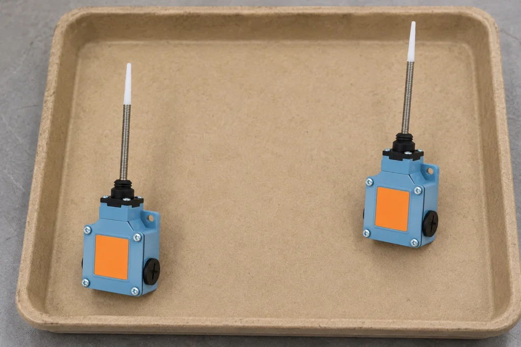
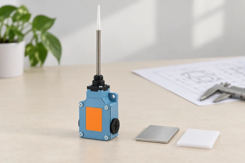
Choosing a metal vs plastic limit switch requires comparing the complete switch against its installation, not declaring one material universally superior. Housing material affects the engineering questions you ask about mechanical loading, conductivity, chemical exposure and assembly. It does not by itself prove an ingress rating, a temperature limit, a safety function or a longer service life. Start with the exact material and model, then request evidence for the conditions your machine creates. This guide compares enclosure-selection decisions for mechanical position switches. The illustrations show a real LEMA metal-body product reference; they do not depict or claim a verified plastic-body equivalent. Compare complete products with the same job A housing is only one part of a limit switch. The actuator transfers target movement, the contact assembly supplies the required electrical state, and the entries and cover form part of the installed enclosure. Two products with different housings may also differ in contact duty, mounting dimensions or actuator travel. A comparison that attributes every difference to metal or plastic can lead to an incompatible substitution. Define the position-detection job first: target approach, movement, repeatability requirement, electrical interface and installation environment. Then compare candidate models against those requirements. Keep the same acceptance criteria for both candidates. If one product has documented evidence and the other has only a general description, record the evidence gap rather than estimating its performance from appearance or price. RealPars' limit switch anatomy and operation lesson helps separate the actuator, enclosure and contact mechanism. The LEMA limit switch application guide provides the broader position-detection context. Use those principles to set up a comparison, then rely on order-code-specific drawings and test information for actual product approval. Name the metal...

Leer más
AC Power Socket Grounding and Protective Earth for Equipment
Blog LEMA Electric

AC Power Socket Grounding and Protective Earth for Equipment

AC power socket grounding is the provision of an approved protective connection from the equipment's required exposed conductive parts through its power interface to the supply's protective system. At an equipment inlet, a third contact is only one part of that path. The mating cord, internal connection, enclosure bonding and installation must also be correct. Protective earth must not be confused with neutral or an electronic signal reference. This guide focuses on OEM equipment interfaces, not instructions for household wiring. Qualified designers and technicians must use the applicable equipment standard, installation requirements and manufacturer documentation when specifying or checking the complete protective arrangement. Identify the equipment protection concept first Determine whether the equipment uses protective earthing, double or reinforced insulation, or another approved protection concept. A plastic outer cover alone does not establish double insulation. A metal enclosure alone does not define the complete earthing arrangement. Obtain the equipment's approved documentation and markings before selecting its inlet or cord assembly. A component chosen only from its apparent contact count can conflict with the protection system already used by the equipment. For equipment that requires protective earth, document the complete path rather than a single green-and-yellow wire. Identify the supply interface, cord protective conductor, inlet contact, internal termination and required bonding points. Record removable covers or assemblies that require a defined connection. Do not rely on paint-covered mechanical fasteners or incidental touching between parts unless the approved design provides and verifies that function. The LEMA IPZ equipment power inlet family is the product reference used here. Its photographs show physical configurations, not proof of a particular assembled machine's safety. Request the selected order-code drawing, terminal identification and applicable component information. A...

Leer más
Limit Switch Troubleshooting: No Signal, Chatter and Misalignment
Blog LEMA Electric

Solución de problemas del interruptor de limitación: Sin señal, ruido y desalineación

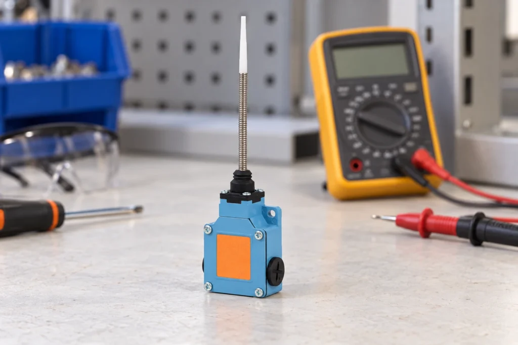
Limit switch troubleshooting should begin by locating where the expected position signal disappears: the machine target, actuator, contacts, cable or receiving controller. Secure the machine before inspection and compare the expected released and operated states with the approved drawing. Replacing the switch before making that comparison can hide a mounting or input fault. This guide concerns mechanical position switches on equipment. It does not cover furnace temperature-limit switches, whose protection function and diagnostic process are different. Never bypass a protective device to keep production running; unresolved safety-related faults require the machine's approved service and validation procedure. Preserve the fault before disturbing the installation Record the machine position, operating mode and symptom before loosening a bracket or disconnecting a cable. Note whether the missing signal occurs on every cycle, only at one travel direction or after a period of operation. Photograph the target-to-actuator relationship and any movement marks on the mounting surface. Keep controller messages and input observations with their timestamps so a later adjustment cannot erase the original evidence. Distinguish the process symptom from the electrical symptom. A carriage failing to stop is not, by itself, proof of a failed contact. The switch may not have been reached, its signal may not have reached the controller, or the control system may have recognised it without producing the expected response. Record what was observed at each boundary. The limit switch application guide explains the position-detection role; that role must be identified in the particular machine. Before hands-on work, follow the equipment's isolation process, including stored energy and motion hazards. OSHA hazardous-energy control requirements provide a United States workplace reference. A stopped drive or an off command is not necessarily an isolated...

Leer más
Foot Switch Cable Length and Strain Relief for Equipment Controls
Blog LEMA Electric

Foot Switch Cable Length and Strain Relief for Equipment Controls

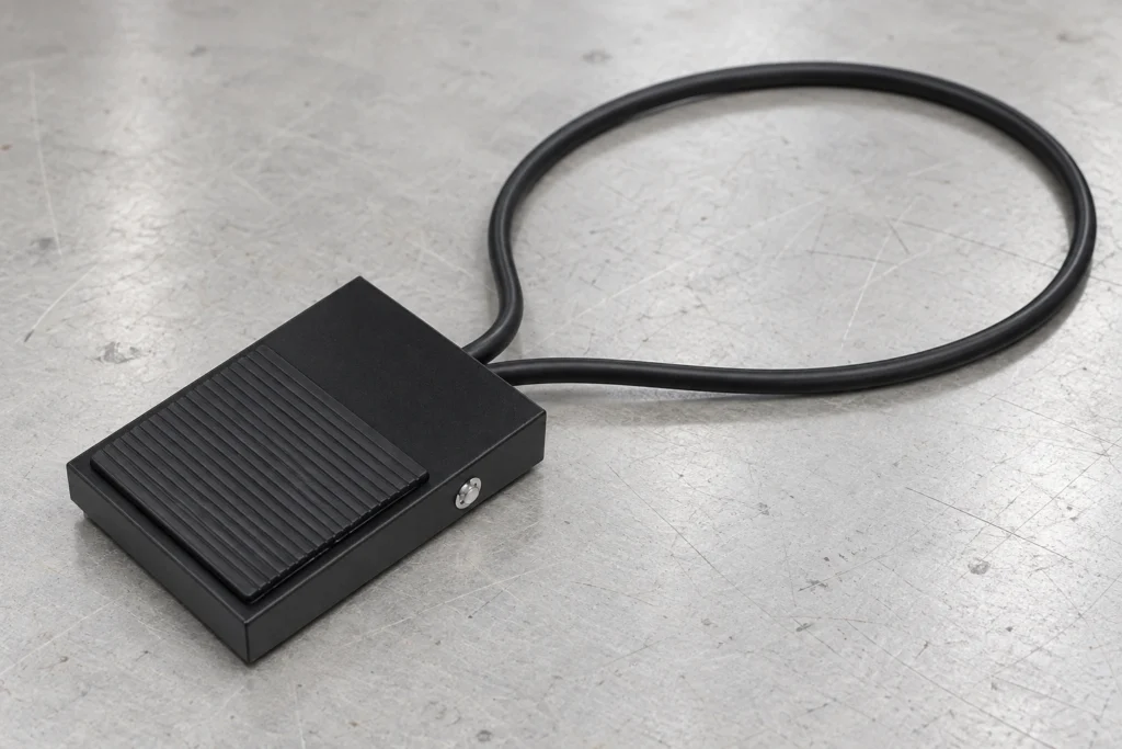
A foot switch cable should reach the intended operating position without pulling on the pedal, connector or internal terminals. Choose its length from the actual route, then verify conductor requirements, electrical interface, environmental exposure and strain relief. A longer cable is not automatically a better cable. Excess slack can create a trip or snag hazard, while a short lead can drag the pedal out of position. This guide covers industrial equipment command pedals, not amplifier accessories. The machine designer must approve the complete pedal, cable and control interface before operation; connector appearance alone cannot establish compatibility. Start with the command circuit, not the cable length Identify what the pedal actually controls. It may close a contact into a low-voltage controller, switch a relay circuit or form part of a manufacturer-defined interface. Those arrangements have different conductor, insulation and protection requirements. Do not assume that a familiar plug carries only a harmless signal. Read the equipment drawing, record the original pedal order code and confirm the supply and receiving input specifications before choosing a cable assembly. A guitar footswitch cable may use a connector that looks similar to an industrial command lead. That resemblance does not prove matching pin assignments, contact action, protective-earth requirements or input behavior. Likewise, an audio shield does not automatically serve as a protective conductor. If the machine documentation is unavailable, keep the equipment out of service until its electrical interface can be established by a qualified person. Use the LEMA LF foot switch product family as a starting point for a model enquiry. The reference photograph confirms an external pedal and attached lead; it does not establish the lead's exact length, conductor size, pinout or suitability...

Leer más
Industrial Limit Switch Replacement: Preserve Position and Validate Timing
Blog LEMA Electric

Reemplazo de interruptores de límite industrial: mantener la posición y validar el tiempo

An industrial limit switch replacement must preserve the original contact function, actuator relationship, mounting geometry and electrical duty, then pass the machine's specified acceptance checks. Matching the housing or screw holes alone does not prove that the new part operates at the same machine position. Record the installation before removal and compare the original and candidate order codes against current drawings. This guide covers mechanical equipment position switches, not furnace temperature-limit devices. It explains how to protect an established setup during an approved repair; it does not guarantee unchanged timing or authorise substituting a generic switch into a safety-related function. Confirm the fault and the approved service scope Establish why a replacement is needed before ordering it. A loose bracket, worn target, cable defect or receiving-input problem can resemble a failed switch. Replacing a sound component can leave that problem unresolved and introduce a new operating-point difference. Use the position-switch troubleshooting guide to organise fault evidence before moving the installation. For the broader position-detection context, see the limit switch application guide. Read the equipment service instructions and approved parts information. Identify whether the repair requires an exact service part, an approved alternative or a formal design review. A component used for ordinary position indication may have different verification requirements from one participating in a protective function. Do not assume an alternate model is acceptable because a supplier describes it as suitable for industrial machinery. Secure the machine using its authorised isolation process, including stored mechanical, pneumatic or hydraulic energy where relevant. OSHA's hazardous-energy control standard is a United States workplace reference for that process within its scope. A limit-switch signal, stop command or controller mode is not a substitute for...

Leer más
Power Socket Contact Resistance: Measurement and Heat Rise
Blog LEMA Electric

Power Socket Contact Resistance: Measurement and Heat Rise

Power socket contact resistance adds electrical loss at the mating interface. Under a given current, a higher resistance produces more local power dissipation, but resistance alone does not predict the final temperature. The contact geometry, surrounding materials, ventilation and operating conditions also matter. For an equipment inlet, evaluate the complete mated connection and the actual application. Start with an isolated, repeatable resistance measurement and a qualified thermal validation plan. Do not use a continuity beep, a cool exterior surface or an unverified catalog number as proof that the connection is suitable. This guide concerns panel-mounted equipment power sockets and inlets, rather than household wall receptacles or RV shore-power connectors. It focuses on how to interpret contact measurements and plan a heat-rise investigation. Work involving installed mains equipment requires qualified personnel, suitable test equipment and the equipment's documented safety procedure. Define the connection being measured Identify the inlet, mating connector, terminals and measurement points. The resistance between two accessible points may include the mating interface, metal within the inlet, the cable termination and part of the cable. Without a clearly stated test boundary, two apparently different contact-resistance results may simply describe different paths. Record the exact inlet and cord-set identities, their condition and whether they are fully mated. Preserve the mounting arrangement and cable support in the test record. A new loose sample on a bench is not necessarily representative of a connection installed in a warm enclosure. Conversely, a measurement including a long cable cannot be described as the inlet's contact resistance alone. The University of Maryland CALCE contact-resistance measurement overview describes evaluation using actual contact geometry and controlled environmental conditions. It supports a central practical distinction: measure the connection...

Leer más
Micro Switch Failure Modes: Evidence and Root-Cause Checks
Blog LEMA Electric

Modos de fallo de los microinterruptores: pruebas de evidencia y determinación de la causa raíz

Micro switch failure modes include a contact that will not establish the intended state, a contact that remains closed, intermittent electrical behavior, and a mechanism that no longer operates at the required position. The useful question is what changed before the failure. Inspect the load, actuator movement, mounting, environment and connection system separately. Replacing a switch without preserving this evidence may restore operation briefly while leaving the original cause in the machine. This guide organizes a root-cause investigation for conventional snap-action micro switches; it does not diagnose a specific returned LEMA part. Begin with the machine's reported symptom and the expected contact function. A controller alarm alone cannot prove that the switch failed. A disconnected cable, changing process position or incorrect input configuration can produce a similar result. Treat the switch as one component in a documented chain from physical movement to accepted control signal. Preserve the evidence before changing the installation Record the switch order code, equipment identity and the last known successful operation. Photograph the installed actuator, terminal connection, bracket and surrounding mechanism before loosening anything. Include the operating conditions at the time of the event: a production change, maintenance visit, washdown, new load, cable rerouting or adjustment may explain why an established installation suddenly changed. Label a removed switch with the machine and position it came from. Keep associated connectors and fastening parts when they may contribute to the investigation. Avoid opening a sealed housing, washing away residue or repeatedly working the actuator before its condition has been recorded. A supplier cannot assess the original condition when cleaning or exploratory damage has already altered it. Separate observations from conclusions in the return record. “Input stayed active after...

Leer más
Micro Switch Contact Bounce: Validate Mechanism Input Events
Blog LEMA Electric

Micro Switch Contact Bounce: Validate Mechanism Input Events

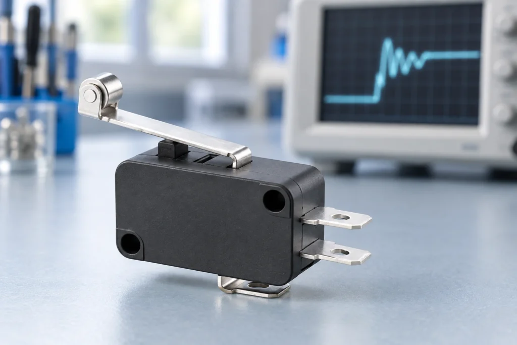
Micro switch contact bounce is a brief series of electrical transitions around a single mechanical switching event. A snap-action mechanism makes the change decisive, but it does not guarantee that a fast controller sees exactly one edge. For a roller-lever or plunger micro switch on an OEM machine, investigate both the contact signal and the motion that operates it. Then accept a stable state or a qualified event at the controller. A debounce delay alone cannot correct a cam that repeatedly crosses the operating point, an overloaded contact, or a damaged harness. This guide focuses on micro switches operated by mechanisms: rollers following cams, plungers touched by moving parts, and small levers detecting position. It addresses event validation, not a generic replacement procedure or a fixed debounce circuit. Start with the actual switch drawing, the controller input specification and a record of the machine movement. The aim is to reject unintended transitions without hiding a genuine position change. Separate one switching event from repeated mechanical actuation A useful first question is whether the actuator makes one controlled pass through the switch point. Contact bounce occurs during contact settling. Mechanical re-actuation occurs when the moving part repeatedly operates and releases the switch. Both can produce multiple edges, but they require different corrections. A loose roller bracket, oscillating linkage or cam dwelling near the release point can keep creating valid mechanical changes long after the first contact transition. The University of Washington Makeability Lab lesson on debouncing explains how moving electrical contacts can oscillate before settling. Use that principle to interpret a short transition cluster, while separately checking whether the machine motion continues to cross the switching boundary. Do not label every...

Leer más
Push Button Switch Replacement: Contacts and Panel Fit
Blog LEMA Electric

Push Button Switch Replacement: Contacts and Panel Fit

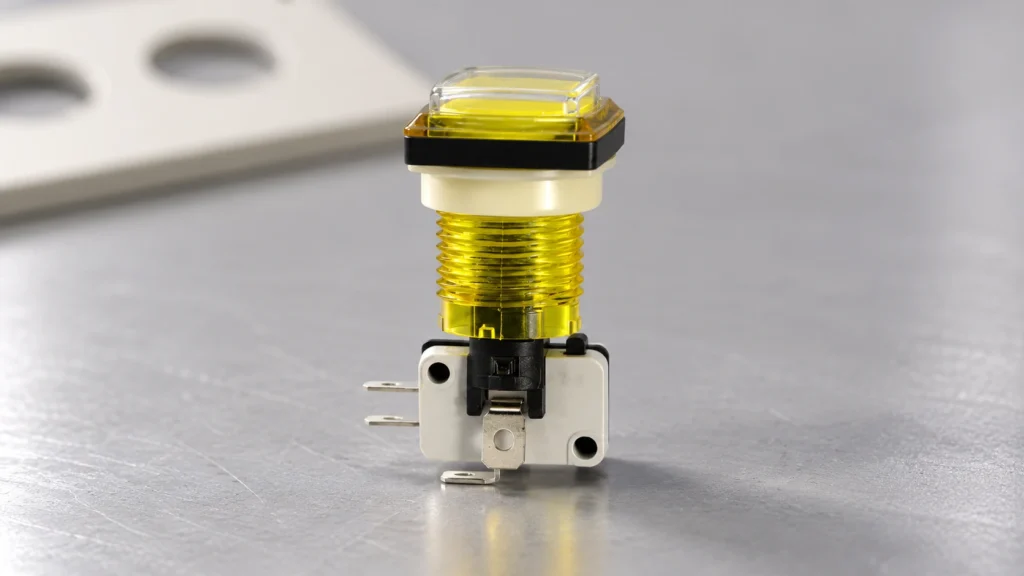
Replace the complete function, not only the visible button A push button switch replacement must preserve the original action, contact arrangement, panel fit, electrical duty and terminal system. If the button is illuminated, the indicator circuit also needs a separate comparison. A similar cap color or the same number of pins does not establish compatibility. Start with the equipment instructions and complete original order code, then compare a current drawing and contact diagram for the candidate. This guide focuses on equipment panel controls and OEM substitution checks; it does not authorize changes to emergency stops, safety interlocks or proprietary service assemblies. The LEMA push button switch range offers product families to review against an application specification. Product photographs can help identify external features, but they cannot prove a contact circuit, cutout dimension or approval. The replacement needs a documented comparison and a defined acceptance test before it enters service. The industrial push button selection guide provides the broader application framework. Use this replacement checklist to compare the original assembly and candidate against that specification, rather than choosing a new circuit function. Decide whether the actuator, contact assembly or entire unit needs replacement Confirm the fault before ordering parts. A jammed cap, damaged contact, loose terminal and failed indicator can produce different symptoms. Use the complementary push button troubleshooting guide to separate those faults. A wiring defect or incorrect control-input configuration will not be corrected by installing a new button. Some panel controls use separate actuator and contact blocks; others are supplied as an integrated assembly. Follow the manufacturer's service instructions. Do not assume contact blocks from different series fit together because their clips look similar. A mechanical attachment can appear...

Leer más
Toggle Switch Replacement: Poles, Throws and Ratings
Blog LEMA Electric

Toggle Switch Replacement: Poles, Throws and Ratings

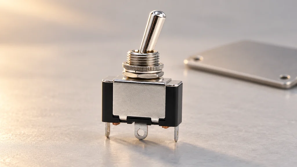
Preserve the original switching function A toggle switch replacement needs to match poles, throws, maintained or momentary action, contact ratings, panel mounting and terminal arrangement. The same number of pins or a similar metal lever does not establish interchangeability. Begin with the equipment circuit and original order code, build a contact-state table, and compare the candidate's current specification. For OEM equipment, a different part is a controlled substitution that requires functional validation. This guide focuses on panel-mounted equipment controls, including the LEMA toggle switch range, rather than household wall-switch wiring, musical-instrument modifications or vehicle-specific repairs. If the equipment manufacturer specifies an approved service part, use that instruction as the starting point. A generic selection checklist cannot override approval requirements or establish that an unlisted component is suitable. Preserve the original machine function and investigate why the old part failed before installing another switch. For the wider operating principle and selection context, see the toggle switch mechanism guide. For a termination comparison, use the solder, screw and quick-connect terminal guide. These references support the replacement comparison; the exact part drawing still controls acceptance. Document the old switch and its circuit Collect the complete switch markings, part number and any suffix. Photograph the actuator, panel mounting and terminal side after following the equipment isolation procedure. Note the orientation of the lever and any locating tab, keyed washer or anti-rotation feature. Record which position corresponds to the displayed equipment command and which circuits are connected in that position. Identify the connected load from the diagram. A toggle can carry load current directly, operate a relay coil or provide a controller input. Those roles impose different requirements. Document voltage, AC or DC, steady current...

Leer más
Micro Switch Replacement: Matching Form, Fit and Function
Blog LEMA Electric

Micro Switch Replacement: Matching Form, Fit and Function

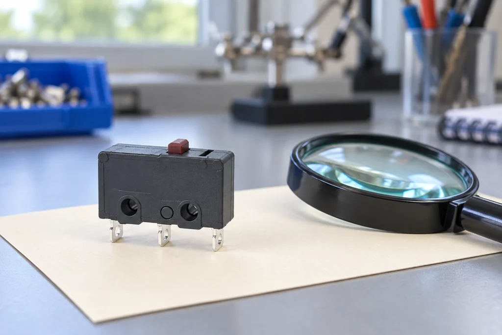
Match the replacement to the machine, not just the switch body A micro switch replacement must match the original contact function, mounting geometry, actuator movement, terminal arrangement and electrical duty. A switch that fits the screw holes can still change the operating point, reverse a control signal or fail prematurely under the connected load. Start with the equipment service instructions and the complete original part number, then compare the proposed replacement against a current drawing and rating sheet. For industrial and appliance assemblies, treat an undocumented substitution as an engineering change requiring validation. This guide explains how to build that comparison without assuming that similar-looking switches are interchangeable. The scope here is a mechanically actuated snap-action component, such as the models in the LEMA micro switch range. It does not provide an approval to replace a machine safety device, a sealed appliance assembly or a manufacturer's proprietary service part. Those cases may require an exact approved component or a complete assembly. Do not bypass an interlock to keep equipment running while a replacement is being sourced. Record the original installation before removing anything Identify the equipment, assembly revision and original switch order code. Photograph the switch from the actuator, mounting and terminal sides, with the circuit isolated. Record the markings exactly, including voltage, current, temperature codes and any separate load-specific ratings. A supplier logo or a partial family name is not enough: terminals, actuators and contact materials can vary within one product family. Record how the actuator contacts the moving mechanism. Note whether a cam touches a roller, a bracket presses a plunger, or a door deflects a lever. Include the normal rest position and the position at which the...

Leer más