CENTRO DE NOTICIAS LEMA

Noticias y Blog

Centro de noticias

Micro Switch Insulation Resistance vs Dielectric Strength
Blog LEMA Electric

Resistencia a la fatiga de la película de aislamiento de los microinterruptores y resistencia dieléctrica

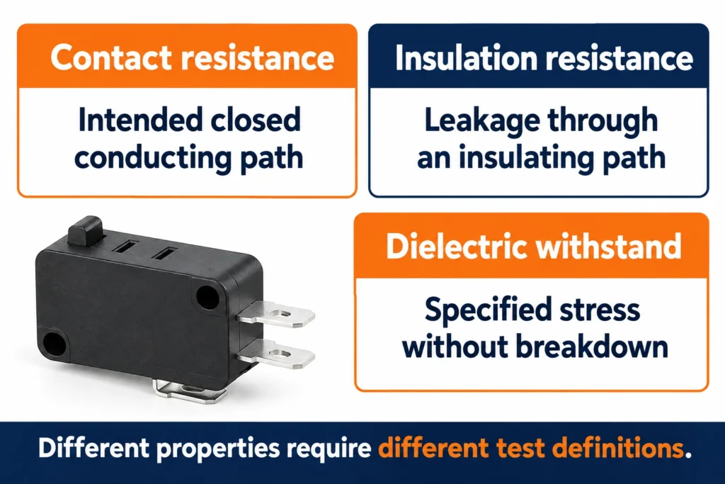
Micro switch insulation resistance and dielectric strength describe different properties. Insulation resistance measures how strongly an insulating path opposes leakage under specified conditions; dielectric strength describes its ability to withstand a specified electrical stress without breakdown. Neither is the resistance of a closed contact. For an OEM component review, compare the test path, contact position, applied voltage, duration and acceptance criteria before comparing headline numbers. A switch with a satisfactory continuity reading has not thereby passed an insulation test, and a published withstand voltage is not a permitted continuous operating voltage. This guide explains how to read a supplier specification and prepare a laboratory request. It does not provide a live high-voltage test procedure. The LEMA KW7 series product page provides a useful example because it lists contact resistance, insulation resistance and dielectric strength separately. Confirm the current specification for the complete order code before using any family-level value in an equipment design. Separate three measurements before reviewing a datasheet Closed-contact resistance concerns the intended conductive path through a contact pair. It matters when assessing connection loss, voltage drop and the condition of the mating contact surfaces. Insulation resistance concerns paths that are intended to remain insulating. These can include separated contacts or a terminal and an accessible conductive part, depending on the component construction and the applicable test specification. A good value for one path does not establish the performance of another. Dielectric withstand testing applies a defined electrical stress and checks the specified acceptance conditions. Those conditions may include leakage limits and the absence of breakdown or flashover. The voltage, waveform, ramp, duration and current limit belong together. Removing these details from a comparison can make two unlike...

Leer más
Equipment Power Inlet Replacement: Match, Inspect and Validate
Blog LEMA Electric

Reemplazo del conector de alimentación del equipo: ajuste, inspección y validación

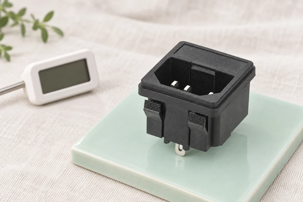
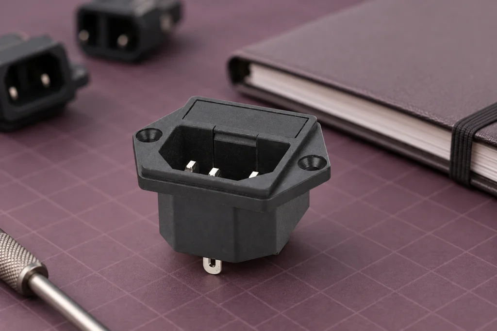
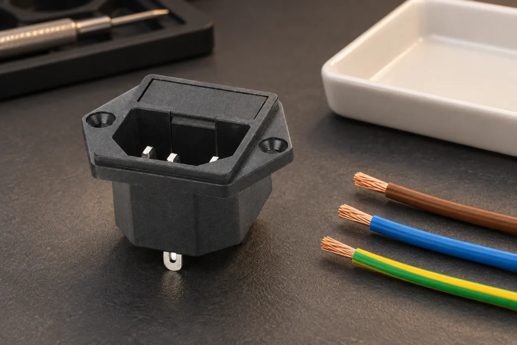
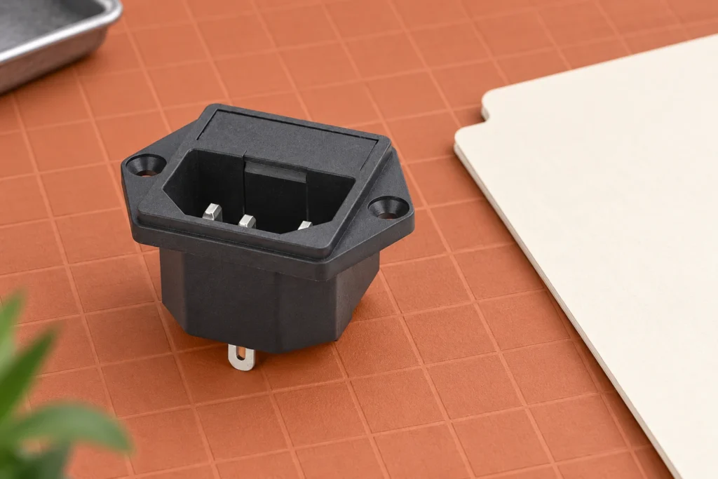
Equipment power inlet replacement requires more than finding a connector that accepts the existing cord. Match the original inlet family, mounting arrangement, approved electrical duty, terminations and protective-earth path, then validate the repaired assembly using the equipment manufacturer's procedure. A physically compatible C14 inlet can still be unsuitable because of different panel retention, rear clearance, contact temperature or approval conditions. Begin with the equipment model and service documentation, not a marketplace photograph. This guide explains how an OEM buyer or qualified maintenance team can document a replacement decision without assuming that every black three-contact inlet is interchangeable. Define the replacement boundary before buyingIdentify whether the failed part is a plain inlet, a combined inlet and fuse holder, or a complete power entry module with switching or filtering. These assemblies may look similar from the front while performing different functions behind the panel. Replacing a complete module with a plain inlet would remove parts of the original circuit and requires an engineering redesign rather than a routine component substitution.Record the equipment manufacturer, model, serial number and original component identification. Obtain the service manual or approved bill of materials when available. If markings are unreadable, do not reverse engineer a current rating from dimensions or contact thickness. Request identification assistance with clear photographs, the panel drawing and the circuit documentation. A damaged part can help identify its geometry, but it does not establish acceptable replacement performance.The LEMA IPZ product family provides an example of equipment inlet construction. The illustrations here are based on the site's screw-mounted product photograph. They show physical features only; they do not certify an installation, identify conductor positions or establish the illustrated variant's current, temperature or regional approval....

Leer más
Micro Switch for Mouse Buttons: OEM Fit and Signal Checks
Blog LEMA Electric

Microinterruptor para botones de ratón: ajuste y verificación de señales según los requisitos del OEM

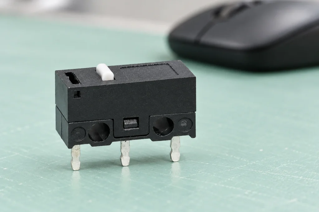
A micro switch for a mouse button must match the complete input assembly: the PCB footprint, terminal function, plunger position, button-shell travel and low-current sensing circuit. A switch that physically enters the holes is not automatically an approved replacement. For an OEM design, evaluate the switch together with the shell and firmware; for a repair, compare the exact original part and verify the assembled result. This guide focuses on mechanical contact switches, using LEMA's KW10-0P as a product-reference example without claiming compatibility with any named mouse or assigning unverified lifetime figures. Identify the input technology before comparing parts Start by determining whether the mouse uses a mechanical contact switch, an optical sensing arrangement or another button mechanism. A mechanical microswitch changes an electrical contact state when its plunger moves. An optical button uses a different sensing path. Similar external button shapes do not make these technologies interchangeable, and a mechanical switch should not be offered as a universal replacement for an optical assembly. Within mechanical designs, record the manufacturer's part marking and the board position. Left and right buttons may use similar switches, while a wheel button or side button can have another package or actuation direction. Photograph the component, its orientation and the surrounding structure before removing anything. Keep the PCB revision in the record because a model name alone may cover several hardware revisions. The LEMA KW10-0P product page provides a real compact PCB-terminal microswitch reference. Its black housing, white plunger and three visible pins are useful for a form comparison. They do not establish the terminal sequence, a particular mouse's compatibility or the operating force of every orderable variant. Request the drawing and specification for the complete...

Leer más
Industrial Foot Switch Troubleshooting: Locate Intermittent Faults
Blog LEMA Electric

Solución de problemas del interruptor de pie industrial: Localice los fallos intermitentes

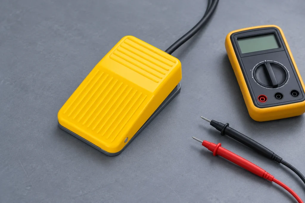
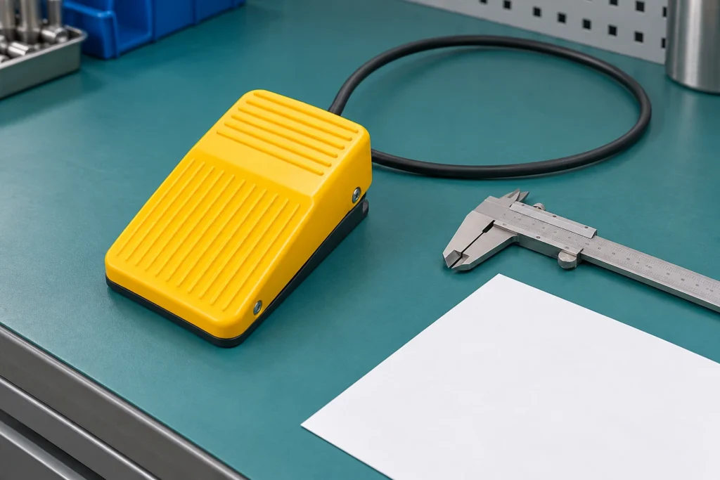
Industrial foot switch troubleshooting starts by separating the pedal mechanism, contact circuit, cable and connector, controller input and machine logic. An intermittent command does not prove that the pedal is defective, and a continuity beep does not prove the complete interface works. Record when the fault occurs, isolate hazardous energy before inspection, and test one part of the signal path at a time using the equipment procedure. This guide focuses on ordinary contact-type industrial command pedals, not speed-control pedals, guitar effects or protective-function devices. Record the symptom before disturbing the evidence Ask what the operator sees: no response, delayed response, operation only at a certain pedal angle, repeated commands or a command that remains active after release. Record the machine state and whether the problem follows cable movement, temperature, a cleaning event or a recent repair. Include the approximate sequence, not merely the phrase "pedal broken". Keep the original part code, controller alarm and wiring revision with the report. Photograph the installed cable route and connector orientation before disconnecting anything. If several identical machines are present, identify the affected machine and pedal separately. A connector moved to another input during diagnosis can otherwise erase the evidence needed to interpret the fault. Distinguish the input signal from the resulting machine motion. The controller may receive the pedal command while another condition prevents movement. An alarm, guard state, process mode or sequence prerequisite can inhibit operation. Repeatedly pressing harder can hide that distinction and damage the pedal without addressing the actual cause. LF-01 yellow ribbed pedal and rear cable beside an inspection notebook on a teal mat. Product-reference illustration, not a dimensioned or wiring drawing. Establish a safe inspection boundary Follow the...

Leer más
Toggle Switch Motor Control: When a Relay Is Needed
Blog LEMA Electric

Control del motor mediante conmutador de conmutación: cuando se necesita un relé

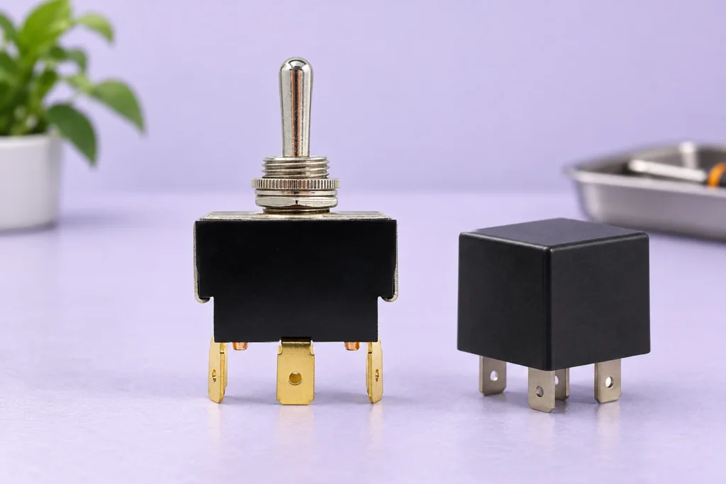
A toggle switch for motor control may operate the motor directly only when the exact switch is documented for that motor's voltage, current type, starting duty and switching conditions. Otherwise, a suitable relay, contactor or electronic motor controller can carry the power while the toggle supplies a command. Adding a relay does not automatically make the circuit suitable: its coil, contacts, protection and restart behavior still need review. This guide helps OEMs separate a maintained toggle command from the motor power path and prepare a complete design request. Identify what the toggle is actually switching Trace the circuit from the operator to the load. In a direct arrangement, motor current passes through the toggle contacts. In an indirect arrangement, the toggle may energize a relay coil or change an input on a motor controller. Those interfaces have different electrical demands, even when the same front-panel lever is used. Record the supply voltage, AC or DC, motor type and intended operation. Starting, stopping, jogging and reversing are different duties. Include the expected operating frequency and the motor manufacturer's starting information. Running current alone cannot describe the contact stress of starting a motor or interrupting an inductive circuit. Where the duty is unknown, obtain measured or manufacturer-supported data before selecting components. Do not interpret an AC resistive rating as a DC motor rating. Likewise, a headline current on a product photograph does not establish a utilization category or a permitted motor size. LEMA LT-series images identify a product family and visible construction. Approval for a particular motor circuit must come from the exact ordered variant's electrical documentation and the equipment design. LT-series metal lever, threaded bushing and three brass terminals on a...

Leer más
Push Button Panel Cutout Size: Drawing and Fit Checks
Blog LEMA Electric

Tamaño de los recortes en el panel de botón: verificación de los dibujos y de la colocación

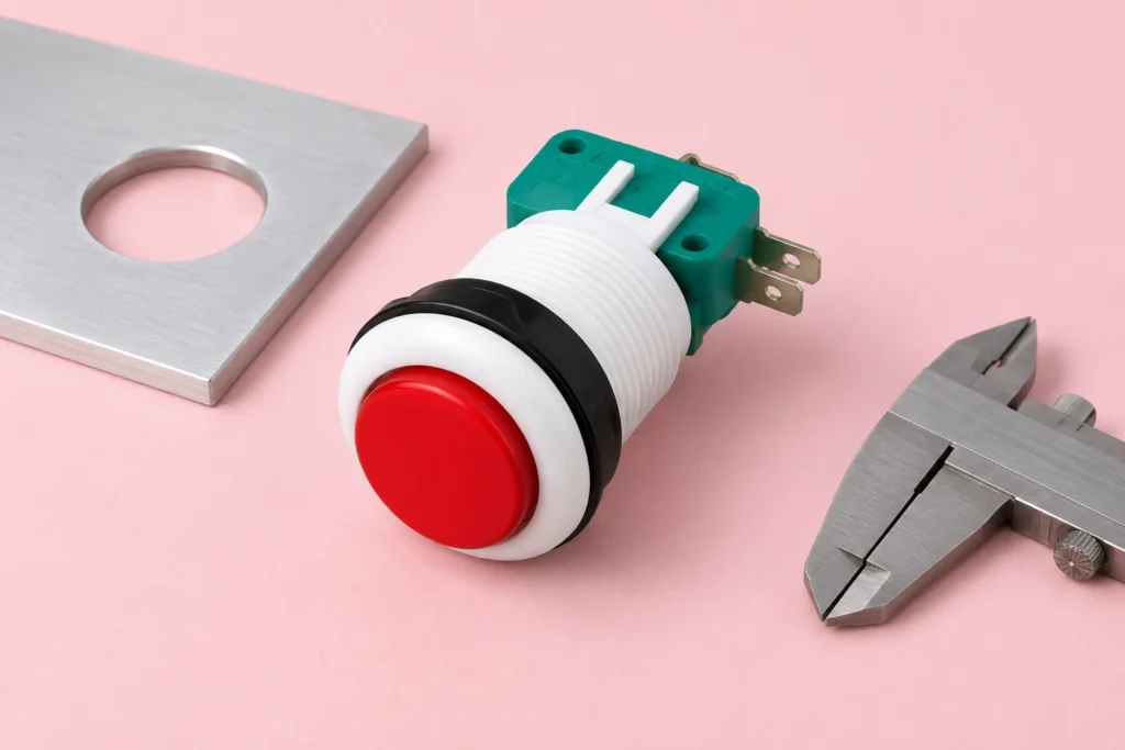
An industrial push button panel cutout size comes from the approved mounting drawing for the exact operator, not from its cap diameter or a generic product-family name. Check the opening shape and tolerance, finished panel thickness, anti-rotation features, retaining hardware and rear clearance together before cutting a production panel. A button that enters the hole can still be poorly retained or impossible to wire. This guide explains how an OEM turns the drawing into a fabrication and sample-inspection record without transferring another manufacturer's dimensions to a LEMA PBS product. Separate the actuator, bezel, mounting body and hole A front-view photograph contains several circles, and only one may describe the mounting interface. The visible actuator is the surface an operator presses. The bezel surrounds it. A threaded body or mounting collar passes through the panel. The drawing specifies the opening that accepts that body, sometimes with a flat, keyway or secondary notch. Measuring the largest visible circle therefore does not identify the required hole. Keep those dimensions in separate fields. Label the front clearance envelope, mounting opening and rear envelope explicitly on your panel layout. The bezel can overlap the opening while the contact block extends sideways behind it. Adjacent operators may clear each other on the front yet interfere through their terminals, clips or cable bends. A complete mounting review follows the whole assembly through the panel. LEMA's PBS original includes front and side views with several different dimensions. Treat those views as product-reference information and request the current drawing for the ordered variant. This article intentionally gives no universal PBS hole diameter: a depicted head measurement, a body dimension and a manufacturing cutout are different quantities. Copying one number...

Leer más
Push Button Switch Current Rating: Match the Contact to the Load
Blog LEMA Electric

Interruptor de botón pulsador: Clasificación de corriente: Seleccione el contacto según la carga

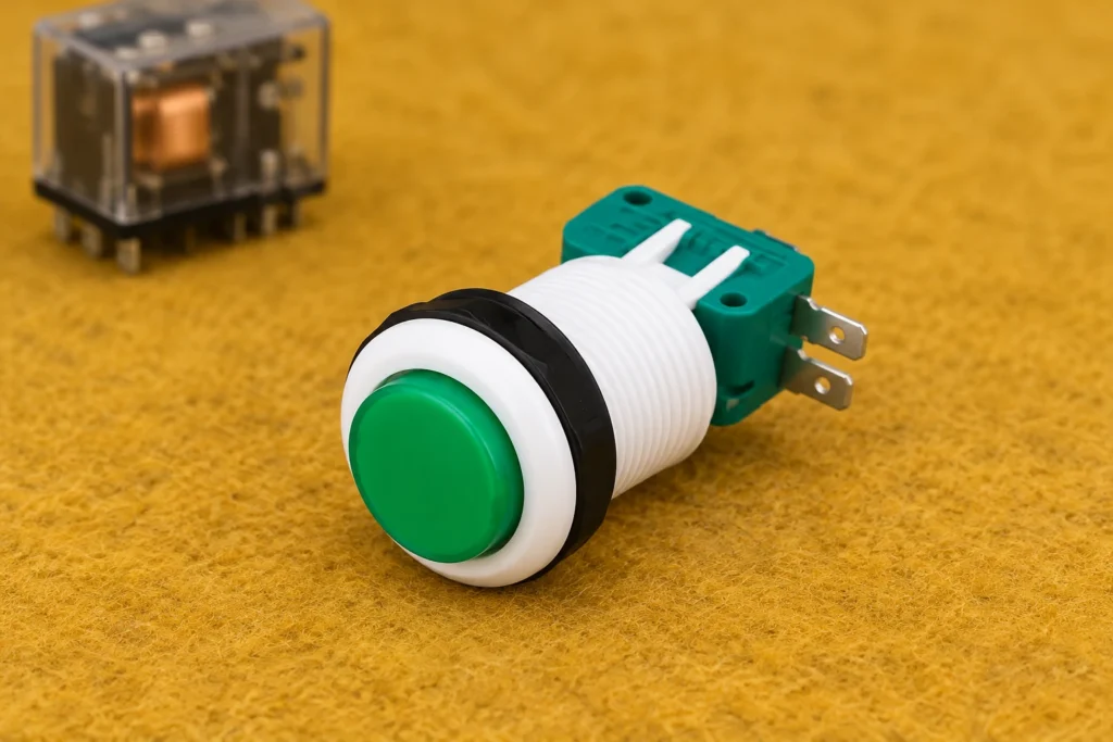
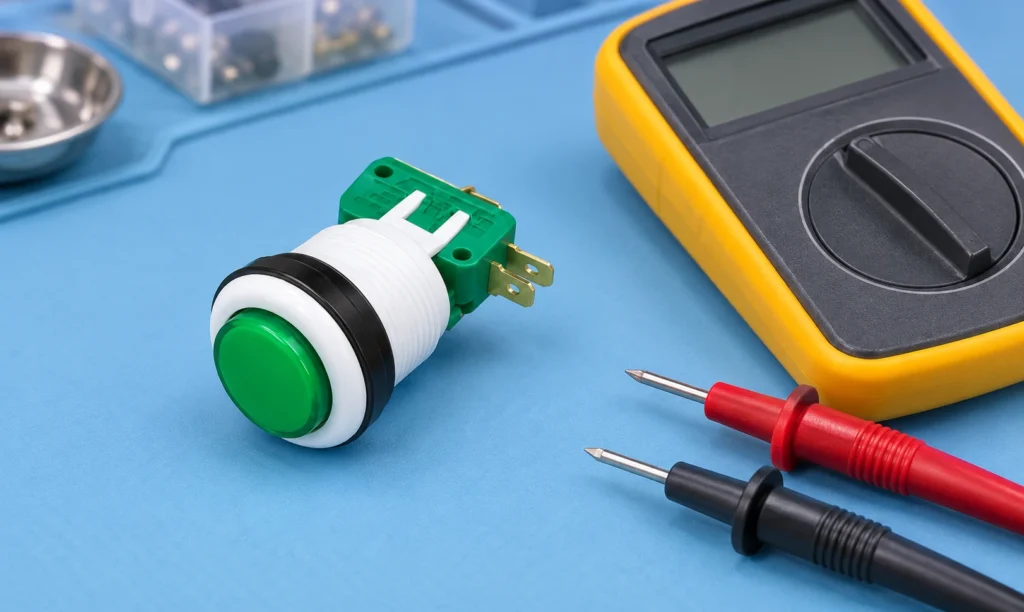
A push button switch current rating applies to a defined electrical duty, not to every load drawing fewer amperes. Match the exact contact's voltage, AC or DC conditions, load type, making and breaking duty, operating frequency and installation conditions. A resistive rating does not automatically approve a motor, solenoid or electronic power supply. A high-current contact is also not necessarily the best choice for a low-level controller input. This guide explains how to collect and compare those requirements before purchasing a push button or approving a component substitution. The focus is contact-load compatibility for equipment controls. Mechanical operation, button colour and terminal count remain separate selection questions. The pictured LEMA PBS-001 button is a physical product reference; no current, voltage or protective-function rating is inferred from its appearance. Electrical measurements and circuit modifications belong to qualified personnel using an approved equipment procedure. Identify what the button actually switches Begin at the schematic. A button may connect directly to a load, operate a relay coil, signal a controller input or perform another defined function. Those arrangements can place very different demands on the contact. Record the electrical component immediately downstream of the button rather than assuming that the machine's motor power flows through the operator control. Trace the actual contact circuit independently of any lamp circuit. An illuminated button can have separate terminals and supply conditions for its indicator. A lamp specification does not describe the switching contact. Equally, the presence of several terminals does not establish a particular internal diagram. Use the drawing for the exact order code and confirm its contact arrangement. The industrial push button selection guide provides the broader mechanical and functional context. This article concentrates on...

Leer más
IEC Inlet Temperature Ratings: Pin Limits, Ambient and Assembly Heat
Blog LEMA Electric

Calificaciones de temperatura de entrada IEC: límites de pin, calor ambiente y calor de montaje

An IEC inlet temperature rating is meaningful only when you know what temperature it describes. Maximum pin temperature, permitted ambient temperature and temperature rise are different quantities. A connector family associated with a higher pin temperature does not automatically approve an inlet for a hotter enclosure or a larger current. Identify the exact inlet, its mating connector and the applicable product documents, then review the thermal conditions of the complete equipment. This guide separates those checks so that buyers do not treat a housing photograph, a material description or a familiar connector name as thermal approval. The intended readers are equipment designers, purchasing teams and qualified maintenance personnel. Illustrations use a real LEMA IPZ snap-in inlet as a visual reference. They do not establish its connector classification, temperature limit or certification. Electrical and thermal testing must follow a procedure defined for the actual equipment; this article does not provide universal acceptance limits. Separate three temperatures before comparing products Pin temperature concerns a specified part of the connection. Ambient temperature concerns the surrounding air under defined conditions. Temperature rise is the measured increase above the reference ambient during a defined test. A document may discuss all three, but a number from one category should never replace a missing number in another. Record the measurement location and condition with every temperature value. Consider a hypothetical component described by a maximum pin temperature. That statement alone does not tell you its permitted local ambient, how much rise it develops at a particular current or whether nearby equipment can expose its plastic body to additional heat. Similarly, a housing material's laboratory property is not a rating for the assembled inlet. Ask for the finished...

Leer más
10A vs 15A IEC Inlet: Compare Approval and the Complete Power Path
Blog LEMA Electric

IEC Inlet 10A vs 15A: Compare la homologación y el recorrido completo de la energía

A 10A vs 15A IEC inlet comparison must start with the exact component approval, its voltage and its intended market. Two numbers on a catalogue page do not necessarily describe two physically different products, and a higher number does not automatically increase the permissible load of the complete equipment. Identify which rating applies to the purchased variant and the matching cord set. Then check the internal wiring, terminals, protective devices and equipment requirements. This guide explains that decision process without assigning a regional current rating or certification to an inlet based on its photograph. It is intended for equipment designers, purchasing teams and competent service personnel. The illustrated LEMA inlet provides a product reference for discussing mounting and identity; it is not an approval certificate. Any live measurements or equipment modifications require qualified personnel following an approved procedure. This article concerns detachable equipment power interfaces rather than replacing domestic wall outlets. Read the rating together with its approval context A useful rating record includes more than amperes. Record the manufacturer, exact order code, voltage, applicable approval scheme, temperature conditions, terminal version and any installation conditions. When a supplier lists both 10A and 15A, ask whether the values come from different certification evaluations or refer to different variants. Do not combine a current from one line with a voltage from another to create a rating that was never declared. The IEC 60320-1 catalogue entry identifies the standard family for appliance coupler general requirements. That entry establishes the subject of the standard, not the approval of a particular purchased inlet. The related standard sheets and the product's certification documents provide the details needed for a specific comparison. Keep the edition used in...

Leer más
How to Test a Push Button Switch With a Multimeter
Blog LEMA Electric

Cómo probar un interruptor de botón pulsador con un multímetro

To test a push button switch with a multimeter, first establish a safe de-energized condition and isolate the contacts from other circuit paths. Identify the intended contact pair from the exact switch drawing, check the meter and leads, then record the reading with the button released, pressed and released again. A normally open pair should change from open to closed when operated; a normally closed pair should do the reverse, according to its documented mechanism. This procedure checks contact-state behavior. It does not prove load capacity, endurance, safety certification or the complete machine response. This guide is a bench measurement and recordkeeping workflow for ordinary discrete push button contacts. Electronic touch buttons, illuminated assemblies and protective devices may require different procedures. The product illustrations show a LEMA PBS example for identification; they are not universal pin-number diagrams or instructions for live testing. Define the question before selecting a meter function Decide whether you need to identify a contact pair, confirm released and operated states, investigate an unstable reading or compare a sample against an approved requirement. These are related questions but have different conclusions. A continuity test can reveal an open connection or a state change. It cannot establish the correct electrical duty for a motor, determine an endurance rating or approve a protective control. For a machine that fails to respond, use the separate push button troubleshooting guide to distinguish actuator, wiring and controller faults. This article focuses on repeatable isolated measurements. Do not remove a working button from its circuit merely because the controller’s response is unfamiliar; start with the equipment schematic and documented command sequence. Have the exact order code, terminal drawing and action description available. Identify...

Leer más
Industrial Foot Switch Replacement: Match Action, Cable and Interface
Blog LEMA Electric

Reemplazo del interruptor de pie industrial: ajuste de acción, cable e interfaz

An industrial foot switch replacement must preserve the original command behavior, electrical interface and installation requirements. A similar pedal shape or matching plug is not enough. Record the original part and machine response, compare the candidate against the approved documentation, and validate the finished assembly before return to service. This guide covers ordinary industrial command pedals and their replacement evidence. It does not approve substitutions in emergency-stop, enabling, guarding or other protective functions, and it does not address guitar effects, sewing-machine speed controllers or household lamp foot switches. For equipment builders and maintenance buyers, the practical question is whether a proposed substitute reproduces the complete approved function. The pedal, cable, connector and receiving input all matter. Keep that comparison separate from a catalogue search so availability does not silently override the machine requirements. Capture the original configuration before removal Record the full pedal order code, visible markings, cable identification, connector details and machine drawing revision. Photograph the as-installed location and routing before moving anything. Note whether the unit is loose on the floor, fixed to a support or part of a guarded station. Include any secondary command, indicator or mechanical feature that participates in normal operation. Write down what the machine does when the operator presses and releases the pedal. Distinguish a momentary command from a maintained state and from a controller that retains a command after a short press. Observe the documented sequence rather than conducting an unsafe experiment. If the machine is already faulty, use the approved description and records; the failed behavior is not the reference that the replacement should reproduce. Consult the industrial electric foot switch selection guide when reconstructing the initial requirements. A replacement review...

Leer más
Equipment Power Socket Polarity: Verify the Complete Supply Path
Blog LEMA Electric

Equipment Power Socket Polarity: Verify the Complete Supply Path

Equipment power socket polarity means the intended line, neutral and protective conductor paths remain correctly identified through the cord, connector, inlet and internal assembly. Alternating current does not make those conductor roles interchangeable. Verify the exact connector drawing and equipment circuit before interpreting a photograph or performing a test. A connector that fits, a machine that powers on, or a three-light socket tester alone does not prove the complete assembly is correct. This guide focuses on equipment inlet identity and verification records, rather than household receptacle repair or a universal pin-position diagram. The intended readers are equipment builders, procurement teams and competent maintenance personnel. Electrical inspection and testing must follow the actual equipment requirements and workplace procedures. The illustrated product is a visual reference, not a verified wiring assignment. Do not infer a terminal function from the location shown in an illustration. Separate polarity from protective earthing In a supply system that distinguishes line and neutral, polarity concerns the connection of those conductors to their intended points. Protective earth, when required by the equipment design, serves a different purpose. It is part of a protective path rather than a substitute return conductor. Do not connect neutral to an enclosure inside the equipment simply because both conductors may have an earth-related relationship elsewhere in a particular supply system. The design determines how the inlet, protective devices and internal circuit relate. A correct inlet termination does not establish that the complete cord assembly or upstream installation is correct. Equally, a correct supply socket cannot compensate for a miswired internal harness. Review these as connected parts of one path, with each boundary clearly identified in the verification record. For the protective-path design itself,...

Leer más