LEMA NEWS CENTER

News & Blog

News Center

Limit Switch Accessories Selection and Integration Guide
Blog LEMA Electric

Auswahl- und Integrationshandbuch für Endschalterzubehör

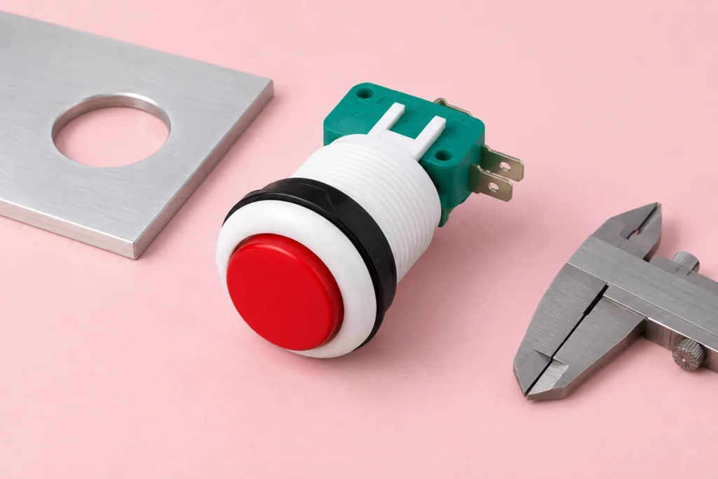
limit switch accessories selection starts by defining the required machine or equipment function, then matching the electrical interface, mechanical mounting and environment to one exact component. This guide explains selecting levers, rollers, rods, brackets, glands, connectors and target cams while preserving mechanical and electrical compatibility. An accessory is part of the sensing system, not a cosmetic add-on. A lever length, roller diameter, bracket stiffness or cable gland can change operating force, travel, sealing, repeatability and service access. Treat every terminal diagram, rating and dimension as model-specific, and validate the assembled system before production use. What the term means in an equipment designAn accessory is part of the sensing system, not a cosmetic add-on. A lever length, roller diameter, bracket stiffness or cable gland can change operating force, travel, sealing, repeatability and service access. This distinction matters because search results often mix replacement parts, hobby wiring examples, complete control assemblies and bare industrial components. An OEM design needs a controlled specification rather than a visual match. Record the intended function in plain language, the normal and actuated states, the equipment supply, the connected load or controller input, and the consequence of a disconnected wire.The component should be considered together with its mating part, mounting structure, conductors, enclosure and controller logic. A correct component installed in an unsuitable cutout or connected to an incompatible load is still an incorrect system. When a seller offers several variants under one family name, request the variant drawing and do not transfer ratings or terminal positions from a neighboring model. Industrial limit switch and actuator hardware for accessory planning. Verify the exact model drawing before production use. Selection decisions that prevent redesignAccessory groupPurposeCompatibility checkActuator head or...

Mehr lesen
Momentary Micro Switch Selection and Actuation Guide
Blog LEMA Electric

Auswahl- und Betätigungsleitfaden für Kurzwahlschalter

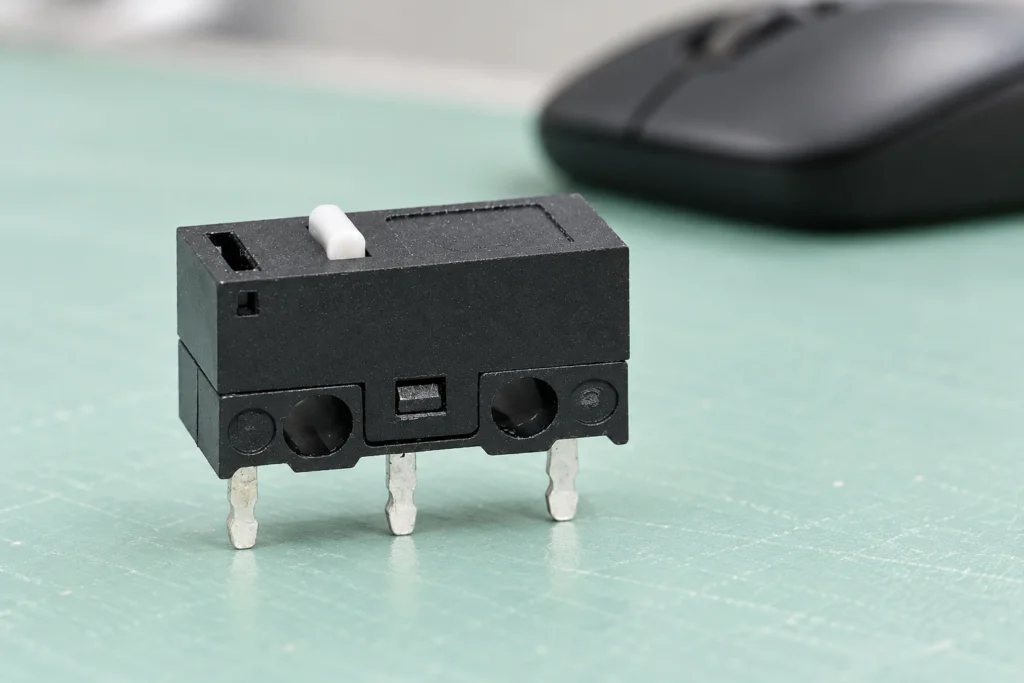
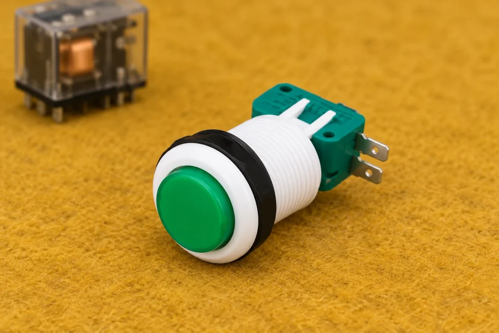
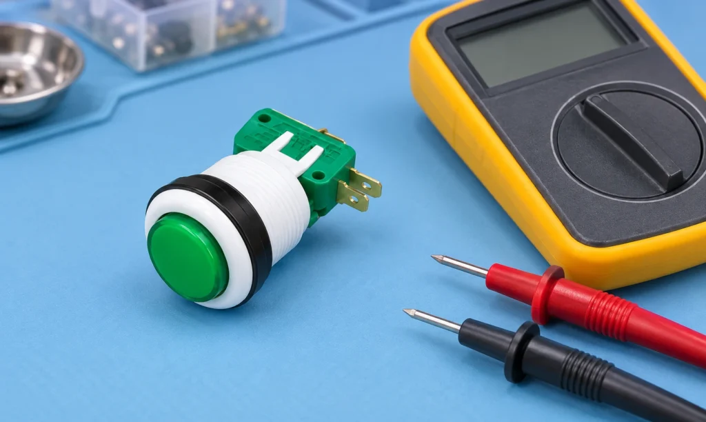
micro switch momentary selection starts by defining the required machine or equipment function, then matching the electrical interface, mechanical mounting and environment to one exact component. This guide explains matching operating and release points to machine travel, choosing an actuator, allowing overtravel, controlling contact logic and testing repeatability. Momentary describes automatic return after force is removed. Snap action describes how the internal contacts change state. The two ideas are related in many micro switches, but they are not interchangeable specifications. Treat every terminal diagram, rating and dimension as model-specific, and validate the assembled system before production use. What the term means in an equipment designMomentary describes automatic return after force is removed. Snap action describes how the internal contacts change state. The two ideas are related in many micro switches, but they are not interchangeable specifications. This distinction matters because search results often mix replacement parts, hobby wiring examples, complete control assemblies and bare industrial components. An OEM design needs a controlled specification rather than a visual match. Record the intended function in plain language, the normal and actuated states, the equipment supply, the connected load or controller input, and the consequence of a disconnected wire.The component should be considered together with its mating part, mounting structure, conductors, enclosure and controller logic. A correct component installed in an unsuitable cutout or connected to an incompatible load is still an incorrect system. When a seller offers several variants under one family name, request the variant drawing and do not transfer ratings or terminal positions from a neighboring model. Momentary micro switch mechanism and actuator area. Verify the exact model drawing before production use. Selection decisions that prevent redesignParameterQuestionFailure avoidedOperating pointWhere must...

Mehr lesen
3-Pin Power Socket Symbol and Schematic Reading Guide
Blog LEMA Electric

3-poliges Stromdosen-Symbol und Anleitung zum Lesen von Schaltplänen

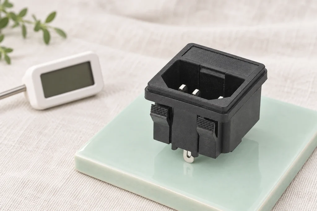
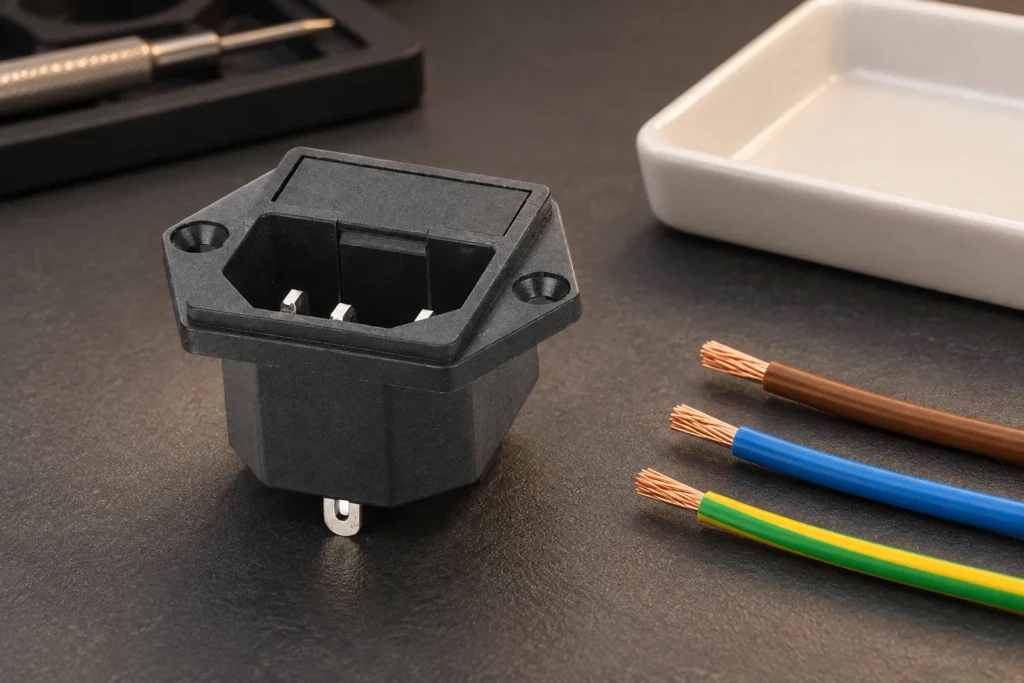
3 pin power socket symbol selection starts by defining the required machine or equipment function, then matching the electrical interface, mechanical mounting and environment to one exact component. This guide explains reading line, neutral and protective-earth indications, separating schematic symbols from physical pin layouts, and cross-checking drawings before wiring. A schematic symbol communicates electrical function. It is not a front-view or rear-view photograph, and it cannot replace the terminal markings and manufacturer drawing for the exact socket. Treat every terminal diagram, rating and dimension as model-specific, and validate the assembled system before production use. What the term means in an equipment designA schematic symbol communicates electrical function. It is not a front-view or rear-view photograph, and it cannot replace the terminal markings and manufacturer drawing for the exact socket. This distinction matters because search results often mix replacement parts, hobby wiring examples, complete control assemblies and bare industrial components. An OEM design needs a controlled specification rather than a visual match. Record the intended function in plain language, the normal and actuated states, the equipment supply, the connected load or controller input, and the consequence of a disconnected wire.The component should be considered together with its mating part, mounting structure, conductors, enclosure and controller logic. A correct component installed in an unsuitable cutout or connected to an incompatible load is still an incorrect system. When a seller offers several variants under one family name, request the variant drawing and do not transfer ratings or terminal positions from a neighboring model. Three-terminal appliance inlet for schematic cross-checking. Verify the exact model drawing before production use. Selection decisions that prevent redesignMarkingTypical design roleDo not assumeL or lineEnergized conductor pathTerminal position without the...

Mehr lesen
Sealed Toggle Switch Selection for Dust, Moisture and Panels
Blog LEMA Electric

Auswahl versiegelter Kippschalter für Staub, Feuchtigkeit und Paneele

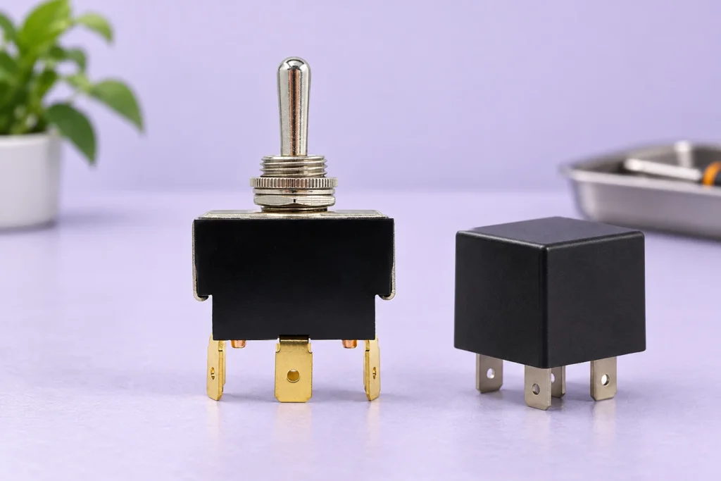
sealed toggle switch selection starts by defining the required machine or equipment function, then matching the electrical interface, mechanical mounting and environment to one exact component. This guide explains defining the real exposure, separating front-of-panel sealing from complete-device protection, selecting boots and gaskets, and validating the assembled panel. A sealed toggle switch does not automatically make an enclosure sealed. Protection depends on the switch construction, panel joint, boot or gasket, rear terminals, mounting quality and every other opening in the enclosure. Treat every terminal diagram, rating and dimension as model-specific, and validate the assembled system before production use. What the term means in an equipment designA sealed toggle switch does not automatically make an enclosure sealed. Protection depends on the switch construction, panel joint, boot or gasket, rear terminals, mounting quality and every other opening in the enclosure. This distinction matters because search results often mix replacement parts, hobby wiring examples, complete control assemblies and bare industrial components. An OEM design needs a controlled specification rather than a visual match. Record the intended function in plain language, the normal and actuated states, the equipment supply, the connected load or controller input, and the consequence of a disconnected wire.The component should be considered together with its mating part, mounting structure, conductors, enclosure and controller logic. A correct component installed in an unsuitable cutout or connected to an incompatible load is still an incorrect system. When a seller offers several variants under one family name, request the variant drawing and do not transfer ratings or terminal positions from a neighboring model. Toggle switch with sealing boot and panel hardware. Verify the exact model drawing before production use. Selection decisions that prevent redesignIngress...

Mehr lesen
SPST Micro Switch Selection and Circuit Integration Guide
Blog LEMA Electric

Auswahl und Schaltungsintegration von SPST-Mikroschaltern

micro switch spst selection starts by defining the required machine or equipment function, then matching the electrical interface, mechanical mounting and environment to one exact component. This guide explains distinguishing SPST-NO from SPST-NC, matching the actuator to the mechanism, checking load conditions, tolerances and life expectations. SPST identifies one pole and one controlled path, but many familiar snap-action micro switches expose COM, NO and NC as an SPDT contact. Confirm the actual terminal diagram instead of choosing from the product silhouette. Treat every terminal diagram, rating and dimension as model-specific, and validate the assembled system before production use. What the term means in an equipment designSPST identifies one pole and one controlled path, but many familiar snap-action micro switches expose COM, NO and NC as an SPDT contact. Confirm the actual terminal diagram instead of choosing from the product silhouette. This distinction matters because search results often mix replacement parts, hobby wiring examples, complete control assemblies and bare industrial components. An OEM design needs a controlled specification rather than a visual match. Record the intended function in plain language, the normal and actuated states, the equipment supply, the connected load or controller input, and the consequence of a disconnected wire.The component should be considered together with its mating part, mounting structure, conductors, enclosure and controller logic. A correct component installed in an unsuitable cutout or connected to an incompatible load is still an incorrect system. When a seller offers several variants under one family name, request the variant drawing and do not transfer ratings or terminal positions from a neighboring model. Compact micro switch body for contact and actuator review. Verify the exact model drawing before production use. Selection decisions...

Mehr lesen
Power Socket Panel Mount Installation and Selection Guide
Blog LEMA Electric

Installations- und Auswahlhandbuch für Gerätesteckdosen zur Frontmontage

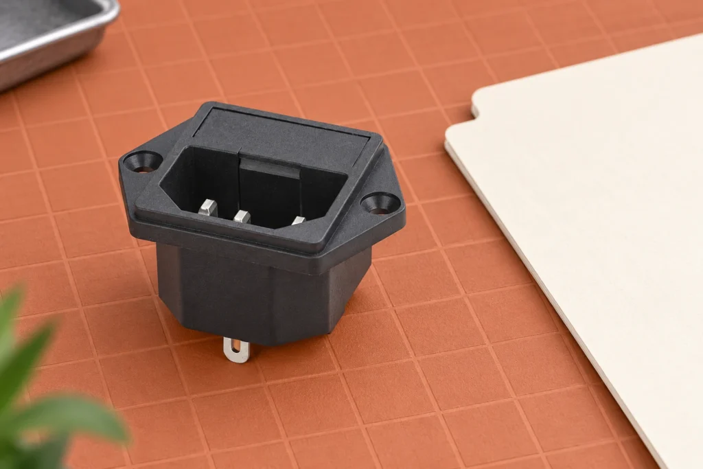
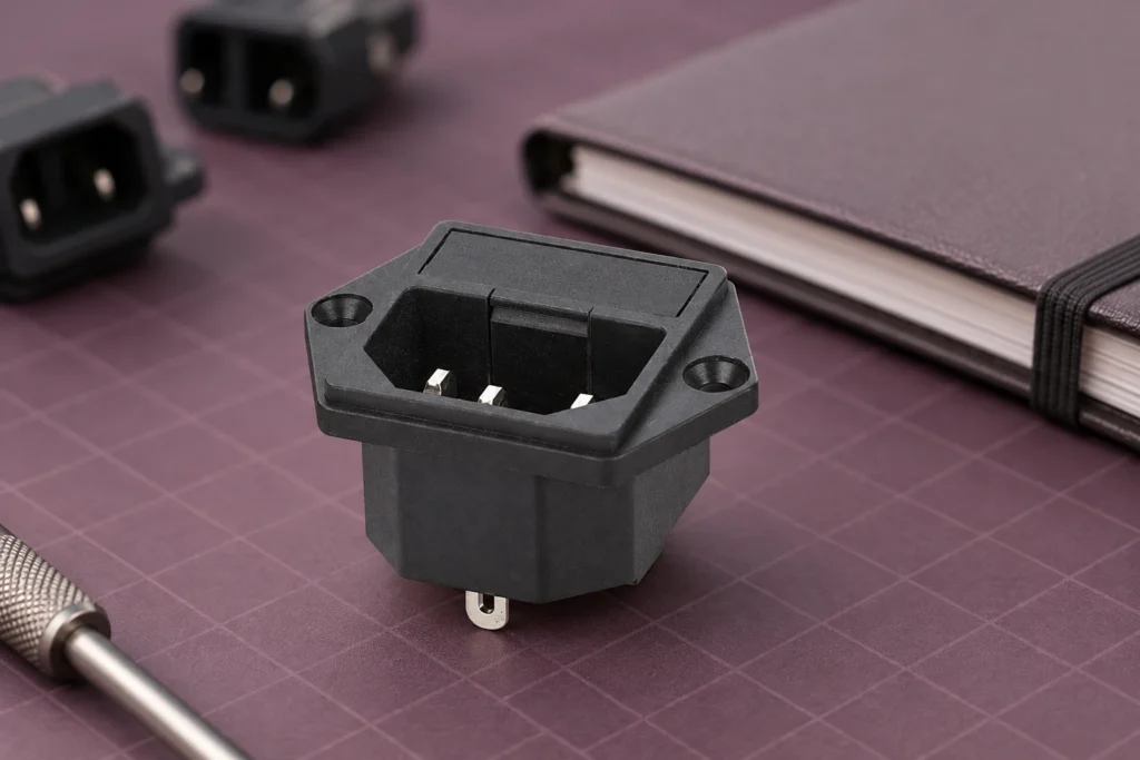
power socket panel mount selection starts by defining the required machine or equipment function, then matching the electrical interface, mechanical mounting and environment to one exact component. This guide explains translating a socket drawing into a correct panel cutout, selecting retention style, managing rear clearance and inspecting the finished installation. Panel mount is a mechanical description rather than a connector standard. Two sockets that look similar from the front can require different cutouts, panel thicknesses, terminal clearances and mating connectors. Treat every terminal diagram, rating and dimension as model-specific, and validate the assembled system before production use. What the term means in an equipment designPanel mount is a mechanical description rather than a connector standard. Two sockets that look similar from the front can require different cutouts, panel thicknesses, terminal clearances and mating connectors. This distinction matters because search results often mix replacement parts, hobby wiring examples, complete control assemblies and bare industrial components. An OEM design needs a controlled specification rather than a visual match. Record the intended function in plain language, the normal and actuated states, the equipment supply, the connected load or controller input, and the consequence of a disconnected wire.The component should be considered together with its mating part, mounting structure, conductors, enclosure and controller logic. A correct component installed in an unsuitable cutout or connected to an incompatible load is still an incorrect system. When a seller offers several variants under one family name, request the variant drawing and do not transfer ratings or terminal positions from a neighboring model. Panel-mounted power inlet viewed from the equipment exterior. Verify the exact model drawing before production use. Selection decisions that prevent redesignMounting issueDrawing checkInstallation checkCutoutNominal size,...

Mehr lesen
Momentary Foot Switch Selection Guide for Industrial Controls
Blog LEMA Electric

Auswahlleitfaden fürmomentane Fußschalter in der Industriesteuerung

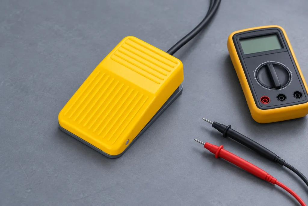
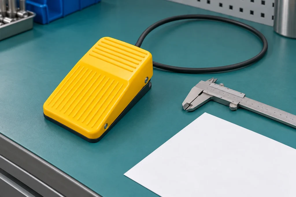
momentary foot switch selection starts by defining the required machine or equipment function, then matching the electrical interface, mechanical mounting and environment to one exact component. This guide explains choosing momentary action, guarding, contact logic, pedal force, cable arrangement and commissioning checks for hands-free control. Momentary action describes how the contact returns after the operator releases the pedal. It does not by itself define safe-stop behavior, electrical rating, enclosure protection or whether the machine may use the pedal as a cycle-start device. Treat every terminal diagram, rating and dimension as model-specific, and validate the assembled system before production use. What the term means in an equipment designMomentary action describes how the contact returns after the operator releases the pedal. It does not by itself define safe-stop behavior, electrical rating, enclosure protection or whether the machine may use the pedal as a cycle-start device. This distinction matters because search results often mix replacement parts, hobby wiring examples, complete control assemblies and bare industrial components. An OEM design needs a controlled specification rather than a visual match. Record the intended function in plain language, the normal and actuated states, the equipment supply, the connected load or controller input, and the consequence of a disconnected wire.The component should be considered together with its mating part, mounting structure, conductors, enclosure and controller logic. A correct component installed in an unsuitable cutout or connected to an incompatible load is still an incorrect system. When a seller offers several variants under one family name, request the variant drawing and do not transfer ratings or terminal positions from a neighboring model. Momentary foot switch body and guarded pedal area. Verify the exact model drawing before production use....

Mehr lesen
C14 Power Socket Selection Guide for Equipment Panels
Blog LEMA Electric

Auswahlleitfaden für C14-Gerätesteckdosen für Gerätepaneele

c14 power socket selection starts by defining the required machine or equipment function, then matching the electrical interface, mechanical mounting and environment to one exact component. This guide explains identifying the C14 interface, selecting panel retention and terminals, coordinating the mating cord, and verifying the complete equipment inlet assembly. C14 describes the appliance inlet interface, not the entire power-entry system. The cord, mating connector, fuse, switch, filter, wiring and protective earth arrangement remain separate design decisions. Treat every terminal diagram, rating and dimension as model-specific, and validate the assembled system before production use. What the term means in an equipment designC14 describes the appliance inlet interface, not the entire power-entry system. The cord, mating connector, fuse, switch, filter, wiring and protective earth arrangement remain separate design decisions. This distinction matters because search results often mix replacement parts, hobby wiring examples, complete control assemblies and bare industrial components. An OEM design needs a controlled specification rather than a visual match. Record the intended function in plain language, the normal and actuated states, the equipment supply, the connected load or controller input, and the consequence of a disconnected wire.The component should be considered together with its mating part, mounting structure, conductors, enclosure and controller logic. A correct component installed in an unsuitable cutout or connected to an incompatible load is still an incorrect system. When a seller offers several variants under one family name, request the variant drawing and do not transfer ratings or terminal positions from a neighboring model. Rear terminal side of an AC appliance inlet for panel integration. Verify the exact model drawing before production use. Selection decisions that prevent redesignSelection pointQuestion for the drawing or supplierEngineering consequenceMating interfaceIs...

Mehr lesen
Foot Pedal Foot Switch Wiring Diagram: Terminals and Connection Checks
Blog LEMA Electric

Schaltplan für Fußschalter: Klemmen und Anschlussprüfungen

foot pedal foot switch wiring diagram selection starts by defining the required machine or equipment function, then matching the electrical interface, mechanical mounting and environment to one exact component. This guide explains how to identify terminals, choose NO or NC behavior, route the cable, test continuity and commission the machine input safely. A foot pedal is only the field input. The control circuit, relay, PLC or machine controller determines what the pedal actually starts, stops or enables. Treat every terminal diagram, rating and dimension as model-specific, and validate the assembled system before production use. What the term means in an equipment designA foot pedal is only the field input. The control circuit, relay, PLC or machine controller determines what the pedal actually starts, stops or enables. This distinction matters because search results often mix replacement parts, hobby wiring examples, complete control assemblies and bare industrial components. An OEM design needs a controlled specification rather than a visual match. Record the intended function in plain language, the normal and actuated states, the equipment supply, the connected load or controller input, and the consequence of a disconnected wire.The component should be considered together with its mating part, mounting structure, conductors, enclosure and controller logic. A correct component installed in an unsuitable cutout or connected to an incompatible load is still an incorrect system. When a seller offers several variants under one family name, request the variant drawing and do not transfer ratings or terminal positions from a neighboring model. Industrial foot switch housing and cable entry for wiring inspection. Verify the exact model drawing before production use. Selection decisions that prevent redesignCheckWhat to verifyWhy it mattersContact logicCOM, NO and NC identified from...

Mehr lesen
CNC Limit Switch Selection, Installation and Homing Guide
Blog LEMA Electric

CNC-Endschalter: Leitfaden für Auswahl, Installation und Referenzfahrt

A CNC limit switch is a position-sensing device used to tell the controller that an axis has reached a defined reference or travel boundary. A reliable installation is not simply a switch placed near the end of a rail: the sensor type, contact logic, mounting rigidity, actuator geometry, cable routing, controller input, and stopping distance must work as one system. For most industrial builds, mechanical roller-lever or plunger switches remain practical choices when they are protected from chips and coolant and are actuated by a repeatable cam. The final circuit and safety functions must always be validated against the machine builder's risk assessment, controller documentation, and applicable regulations. A rigid cam should contact the roller progressively before the carriage reaches the mechanical hard stop. What a CNC limit switch actually does The phrase “limit switch” is often used for three related but different functions. A home switch gives the controller a repeatable reference for the machine coordinate system. A travel limit signals that an axis has reached the permitted physical travel boundary. A soft limit is a software boundary calculated after a successful homing cycle. LinuxCNC documentation makes the relationship clear: homing establishes the machine origin, while soft limits are defined relative to that origin and stop commanded movement before the physical limit switches. One physical switch can sometimes serve as both home and limit input, but that is a controller-design decision rather than a universal wiring rule. The homing sequence may need to ignore or reinterpret a limit input while the axis approaches, trips, reverses, and moves to its final home position. Use the machine controller's documented input scheme instead of copying a generic diagram. A travel switch also...

Mehr lesen
Custom Push Button Switch: OEM RFQ and Sample Checklist
Blog LEMA Electric

Kundenspezifischer Drucktastenschalter: OEM-Anfrage und Muster-Checkliste

A Custom Push Button Switch RFQ only works when you tell the supplier which changes are true engineering modifications—and which fields are still open—instead of sending a photo and a quantity. This page separates catalog configuration from custom work, shows what to write for contact changes, mounting dimensions, wire length, legend or imprint, and sealing, and ends with a sample gate so production does not inherit a bench-only approval. ContentsCustom Configuration vs Custom ModificationWhat a Custom Push Button Switch RFQ Must LockMechanical Interface Fields Buyers ForgetCustom Modification Fields Beyond Catalog OptionsAction, Contacts, and Control-Circuit LanguageWhen Illumination Belongs in the RFQEnvironment, Vibration, and Sealing in the RFQSample Checklist Before You Freeze the BOMMapping the Checklist to PBS Series Product OptionsSend a Complete Package via Contact UsFAQ Custom Configuration vs Custom Modification Buyers say “custom push button” for two different jobs. Suppliers quote the wrong part when those jobs are mixed in one email. Catalog configuration picks published options on an existing family—head color, LED on or off, contact arrangement offered on that series, terminal style already tooled. The supplier maps your checklist to a stock or lightly configured SKU. Custom modification asks for a change that is not a simple option code: a different actuator geometry, a non-standard panel cutout or thread length, a pre-wired harness length, a laser-etched legend, a contact block not offered on the catalog page, or extra sealing beyond the published description. That path needs drawings, tolerances, approval samples, and explicit “feasibility TBD” flags—not a color code alone. Write the RFQ in two labeled blocks: Configuration fields (what you can select from published options) and Modification fields (what must be engineered or tooled). If every line sits...

Mehr lesen
Flush Push Button Switch: Panel Clearance and Actuation
Blog LEMA Electric

Bündiger Drucktastenschalter: Ausschnitt und Betätigung

A Flush Push Button Switch keeps the actuator near the panel face so routine start and reset commands need a deliberate finger press rather than a casual bump. This guide compares flush and projected heads, turns that choice into drawing checks for cutout, thickness, and rear keep-out, and shows when supplier colour or LED options matter—only after head geometry is proven on a sample or approved drawing. What a flush push button switch changes on the panel A flush head sits close to the bezel or panel plane, so sleeves, tools, and leaning operators are less likely to trigger a command by accident. Industrial flush-versus-projected guides describe that near-level profile as a way to keep start and reset actions intentional on busy doors and operator stations—not as a guarantee that every family publishes the same front height. That change is mechanical, not cosmetic. The same panel can look tidy while still failing if the rear body fights a cable duct, or if the operator cannot feel a clean press through gloves. Treat the flush silhouette as one input in a larger clearance and actuation package. On a packaging line start station beside a narrow walkway, a low-profile head reduces “lean and go” mistakes. The trade-off appears in cold-storage panels where thick gloves make a shallow face hard to find: the same profile that blocks accidental hits can slow intentional ones. Flush vs projected heads: choosing actuation intent Choose a flush head when the command should take a conscious finger press; choose a projected / extended head when the operator must find and hit the control quickly, including with gloves. The Wikipedia push-button overview notes that regular flush-mounted buttons can be...

Mehr lesen