LEMA NACHRICHTENZENTRUM

Nachrichten & Blog

Nachrichtenzentrum

Push Button Cap Gloss Inspection: Compare Appearance Consistently
Blog LEMA Electric

Push Button Cap Gloss Inspection: Compare Appearance Consistently

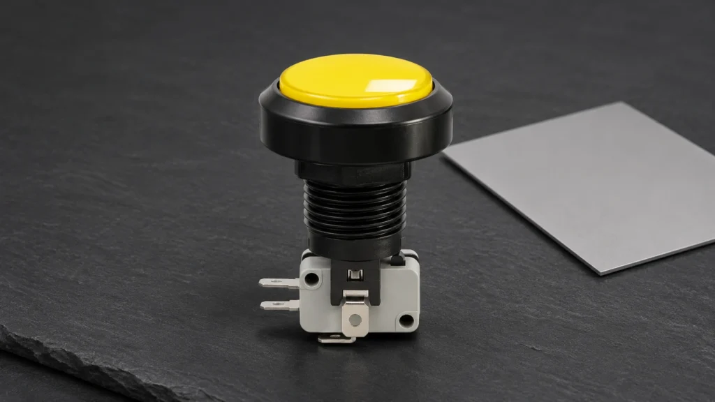
Push button cap specular gloss inspection needs an agreed reference, a defined viewing or measurement method, and identification of the exact cap being assessed. Compare clean, identified samples under consistent conditions before deciding whether an appearance difference is a production issue. A numerical gloss result is useful only when the instrument and specimen are suitable for the comparison. Do not accept or reject a curved button cap using an unexplained number from a flat material plaque. This guide helps OEM buyers specify the evidence they need; it establishes no universal gloss limit or particular resin for Lemaele PBS caps.Define the appearance question before ordering a testGloss is the subject of this inspection, rather than cap colour consistency, scratches or electrical operation. A cap may look different because of the lighting, its orientation or a change in surface condition. Describe the complaint with identified samples and photographs before assigning a cause. Ask whether the purchase requirement concerns a visual match or an instrumental quantity. Those decisions can require different evidence.The PBS series push button product page provides the product family for this discussion. Confirm the selected cap shape, colour, finish and ordering configuration with Lemaele. A family photograph is not a material declaration or approved appearance master. The industrial push button selection guide covers the broader application decisions surrounding that choice.Identify the user-visible surface. The centre of the operating face, a rounded edge and the surrounding bezel can present different geometries. Do not combine observations from these surfaces into one unexplained verdict. Mark the inspection region on a reference photograph and state which areas are excluded, such as the threaded mounting body or the underside contact assembly.Use the same conditions for...

Mehr lesen
Power Inlet Molding Shrinkage: Request Finished-Part Dimensional Evidence
Blog LEMA Electric

Power Inlet Molding Shrinkage: Request Finished-Part Dimensional Evidence

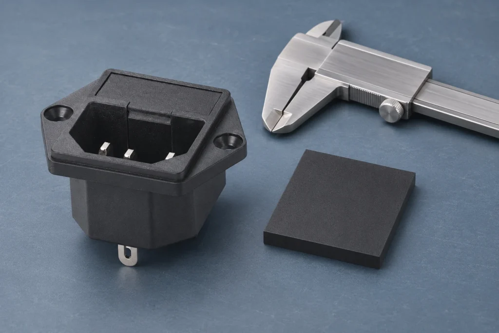
Power inlet molding shrinkage dimensional evidence should connect the identified material and production process to measurements of the finished inlet housing. A resin datasheet value is useful background, but it does not prove that a delivered flange, cavity or mounting feature meets its drawing. Request the selected inlet configuration, material identification, controlled dimensions and representative inspection records. Keep material-specimen shrinkage separate from actual component acceptance and from panel fit. This guide helps OEM buyers ask for relevant evidence; it does not identify the IPZ housing polymer, specify a shrinkage percentage or infer dimensional conformity from a catalog image.Separate material data from the component requirementThe finished housing is the purchasing subject. A material test specimen is a different object made under its own defined conditions. Start by listing the inlet features that matter to the intended assembly, using the supplier drawing and the equipment design. Do not turn every available resin property into an acceptance requirement without an application reason.The IPZ Series AC Power Socket is the relevant family reference. Confirm the exact mounting version and supplied drawing because the family image includes different mounting arrangements. The snap-in versus screw-mount inlet guide explains that selection boundary. This article concerns dimensional evidence from molding, rather than choosing the mounting system.Ask the supplier to identify the housing material under the applicable disclosure arrangement. Do not presume a polymer from color, hardness by touch or an unrelated product in the same catalog. Where detailed formulation is confidential, agree which controlled material identifier and conformity record are sufficient for the order.Understand what a shrinkage standard can establishThe public scope of ASTM D955 concerns shrinkage measurements on molded thermoplastic specimens. It expressly limits transferring those specimen...

Mehr lesen
Micro Switch Terminal Coplanarity: Verify the Drawing Before Measuring
Blog LEMA Electric

Micro Switch Terminal Coplanarity: Verify the Drawing Before Measuring

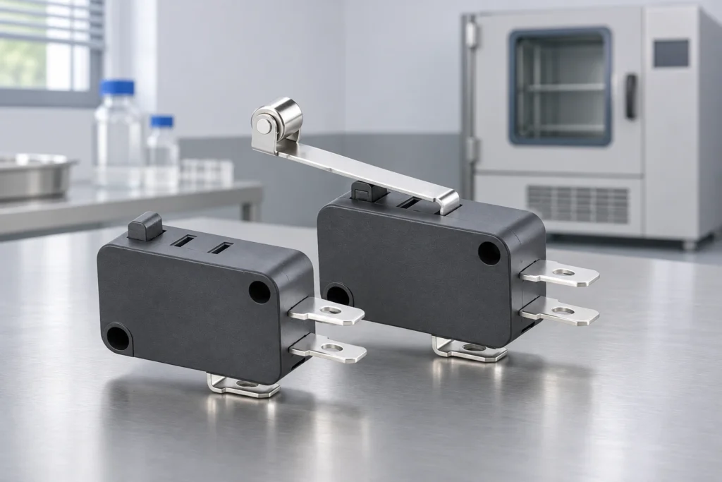
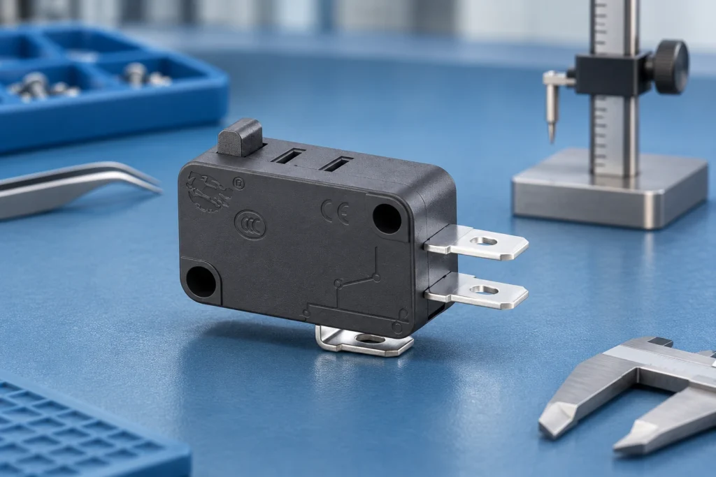
Micro switch terminal coplanarity inspection is useful only when the selected terminal configuration and assembly drawing define which surfaces should share a plane. First confirm the switch variant, intended connection and reference features. Then measure the specified terminal locations using a method that does not bend them into an apparent pass. Spade tabs, solder terminals and board-mount leads should not inherit the same assumed requirement. For an OEM order, request the controlled terminal drawing and acceptance criteria before buying a generic coplanarity test. This guide explains how to organize that evidence without inventing a KW7 tolerance or treating every microswitch as a surface-mount component.Confirm that coplanarity is the actual assembly concernTerminal position relative to an intended common plane is separate from terminal strength, solderability and contact resistance. Identify the assembly feature that needs alignment. A harness using individual receptacles may have a different concern from a rigid board interface. Do not choose the test merely because the terminal ends look uneven in a perspective photograph.The KW7 Series Micro Switch KW7-0 Black Switch with CE CQC presents a family with different actuator and terminal options. Confirm the purchased version with the supplier rather than treating one catalog image as a complete dimensional drawing. The micro switch terminal types guide helps organize those connection choices before a dimensional review.If the assembly interference is actually caused by terminal spacing, angle or clearance, call it that. A coplanarity report may not capture those characteristics. Mark the specific contact region or lead feature on the approved drawing and explain how it interacts with the mating part. The inspection request should answer that interface question.Establish the reference before collecting heightsAsk which features locate the switch in...

Mehr lesen
Toggle Switch Handle Surface Roughness: Define a Repeatable Inspection
Blog LEMA Electric

Toggle Switch Handle Surface Roughness: Define a Repeatable Inspection

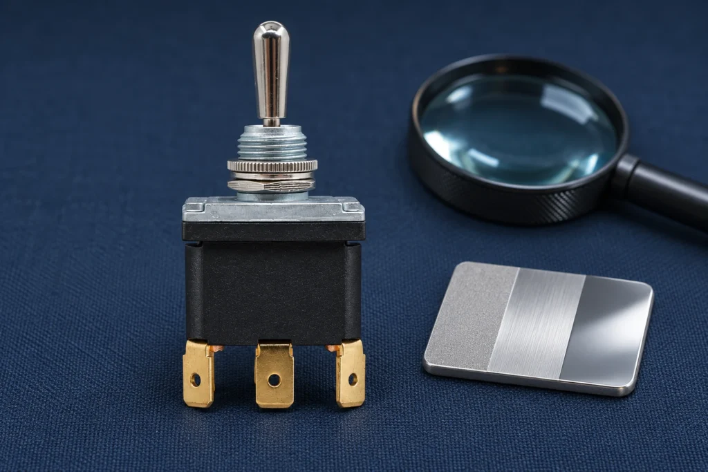
Toggle switch handle surface roughness inspection should begin with a defined surface, an agreed finish requirement and a method that can examine the curved handle without damaging it. A shiny appearance or a smooth feel does not establish a numerical roughness value. Separate visible burrs and coating defects from measured texture, then compare each finding with the approved drawing or sample. For an OEM purchase, ask which handle variant and finish were supplied before requesting a test. This guide organizes that inspection and its records; it does not prescribe a universal roughness limit or claim a particular finish for every Lemaele toggle switch.Identify the handle surface covered by the requirementThe user-contact handle surface is a different inspection subject from the mounting thread, pivot mechanism or electrical contacts. Define whether the requirement covers the rounded tip, the sides, a seam, or another identified region. A result from an easy-to-reach patch cannot automatically represent the entire handle. Include an annotated drawing or photograph that identifies the area without concealing it with labels.The LT3230C Spade Terminal Heavy Duty Toggle Switch DPDT ON-OFF-ON provides a concrete product reference for the inquiry. Use the selected ordering configuration and current drawing to confirm the handle geometry and finish. Do not infer a coating material, roughness value or polishing process from the product photograph. The broader metal toggle switch selection guide addresses the surrounding purchasing decisions.Ask why surface condition matters in the application. A cosmetic match, comfortable manual contact, resistance to snagging and a controlled manufacturing finish can require different evidence. Translate the actual concern into an inspectable requirement. A single roughness number may not describe a sharp isolated edge or a visible scratch that matters to...

Mehr lesen
Limit Switch Cam Target Hardness: Ask for Evidence Before Specifying a Value
Blog LEMA Electric

Limit Switch Cam Target Hardness: Ask for Evidence Before Specifying a Value

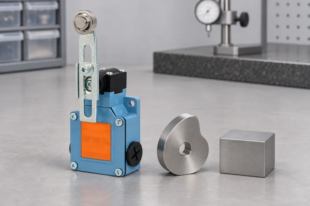
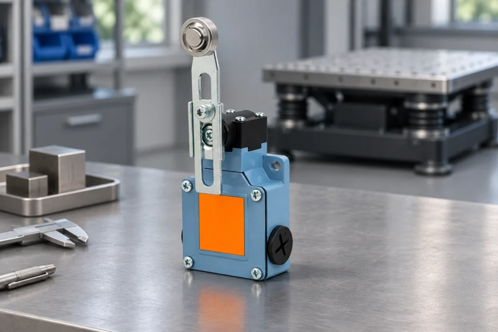
Limit switch cam target surface hardness evidence should identify the separate mating cam, its material and condition, the test method and scale, and the locations actually tested. A bare hardness number is not enough to approve the interface. Confirm whether the result concerns the working surface, an underlying region or a representative coupon. Then review it together with cam shape, alignment and application conditions. No universal hardness value can be assigned to every roller limit switch, and a harder target does not by itself demonstrate longer switch life or acceptable operation.Identify the part that the hardness report describesThe cam or dog is the external machine part that actuates the switch. The roller, lever and switch housing are different components. A hardness certificate for the cam stock does not establish the roller material or the switch’s durability. Begin the review by placing the cam drawing and switch ordering information beside the report, with each component identified separately.The Lemaele LZ1 series product page supplies product-family information, but it does not prescribe the material or surface hardness of every customer-designed cam. Request application guidance for the selected actuator and use the machine designer’s controlled cam drawing. Do not infer a target hardness from the visible silver roller or the switch housing description.This is an evidence review for an existing or proposed mating part. For the overall actuator choice, begin with the limit switch actuator types guide. For the shape and travel of the target, use the separate cam profile design review. Those decisions remain necessary even when the hardness documentation is complete.LZ1 roller lever limit switch beside a separate unattached cam target coupon. Product-reference illustration; not a test result or approved test fixture.Read...

Mehr lesen
Power Inlet Mounting Flange Flatness: Inspect Seating Before Tightening
Blog LEMA Electric

Power Inlet Mounting Flange Flatness: Inspect Seating Before Tightening

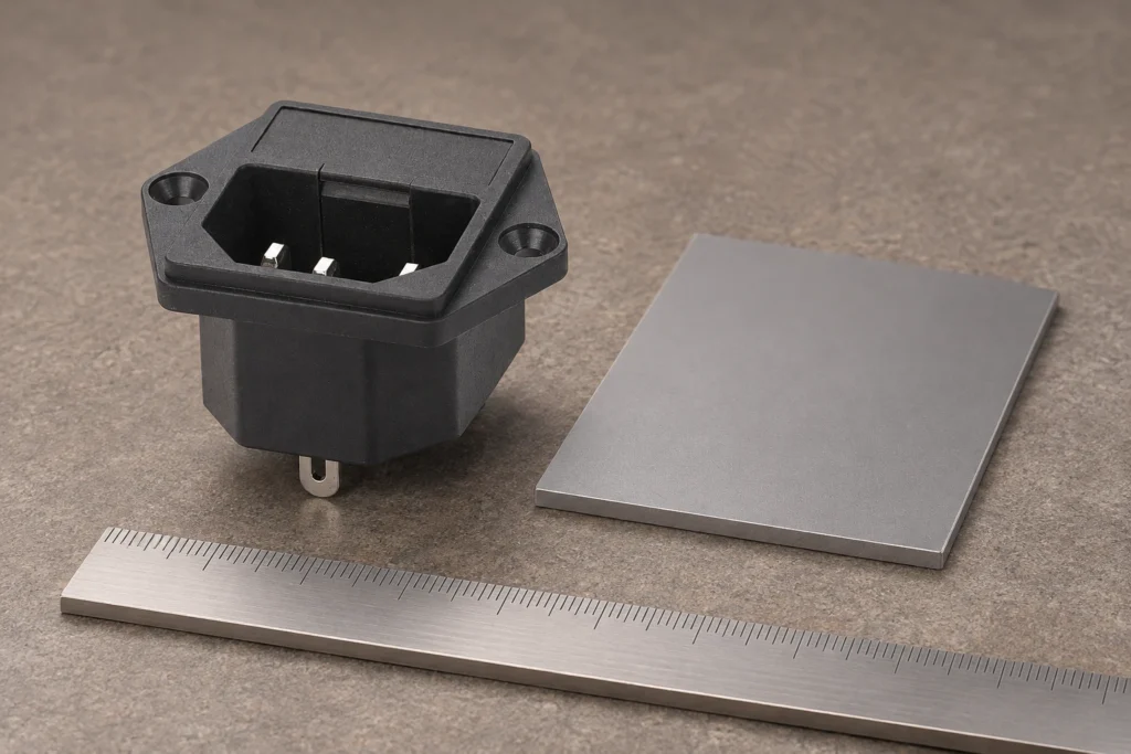
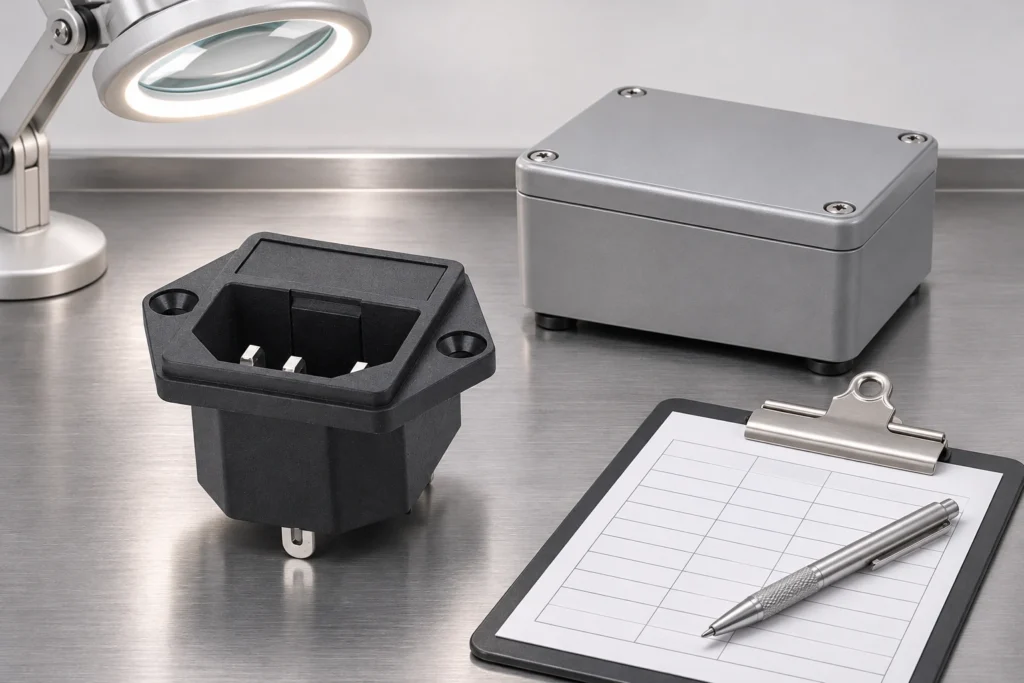
Power inlet mounting flange flatness inspection begins by identifying the intended seating surface and the condition in which it must be checked. Examine the loose inlet and panel separately before tightening screws. Remove only permitted loose contamination, record rocking or visible gaps, and compare measurements with the approved drawing and agreed method. A flange that pulls down when screws are tightened has not automatically passed a flatness check. The assembly may be deforming to match the panel. Distinguish the inlet’s own form from panel distortion, surface obstruction and the fit of the complete mounted equipment.Decide whether you are checking form or assembled fitFlatness concerns the form of a defined surface. Seating concerns how two real parts contact in a particular arrangement. These questions overlap, but they are not interchangeable. A flat flange can sit poorly on a distorted panel, and an uneven flange can appear flush after forced assembly. State which question the inspection is intended to answer before selecting a fixture.A mounting flange may contain ribs, recessed regions, molded features or local contact pads. Do not treat every visible exterior face as the intended mounting plane. Obtain the supplier drawing and identify the functional seating regions. If the drawing does not specify a flatness requirement, ask for the relevant assembly acceptance criteria rather than inventing a numerical limit.The IPZ series product page shows mounting variants. Confirm the exact screw-mount version before planning a flange check. A snap-in body has a different retention interface, so a procedure developed for screw ears should not be transferred without review. The mounting style comparison helps distinguish those interfaces.Close view of IPZ inlet flange seating edge beside an unattached panel sample. Product-reference illustration; not...

Mehr lesen
Foot Switch Cable Conductor Strand Verification: Check the Ordered Construction
Blog LEMA Electric

Foot Switch Cable Conductor Strand Verification: Check the Ordered Construction

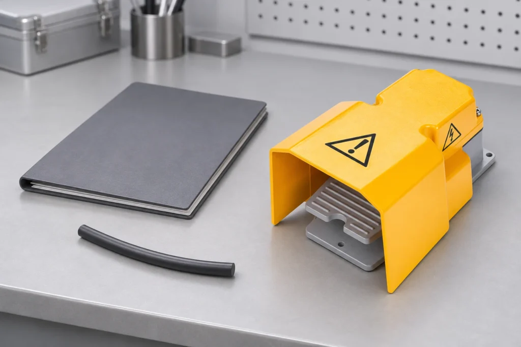
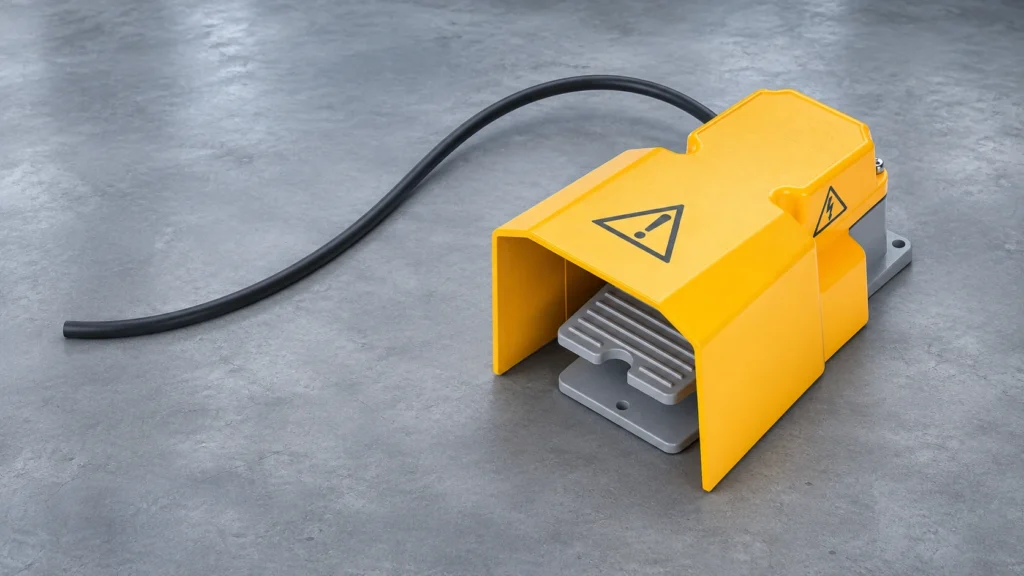
Foot switch cable conductor strand verification starts with the approved cable construction, not with how flexible the finished cord feels. Match the ordered cable part number and revision to supplier records, identify the conductor material and declared stranding, and use a traceable sacrificial sample when a physical examination is required. Record which conductor was examined and how the sample was prepared. A continuity reading can support an electrical check, but it does not identify the number or condition of individual strands. Keep construction acceptance separate from bend-life qualification, terminal approval and the safety assessment of the finished machine.Define the cable being purchased before counting strandsA purchasing description such as “flexible black cable” leaves important questions unanswered. Request the cable manufacturer or controlled supplier code, conductor count, nominal conductor size, insulation and jacket identification, and the drawing revision supplied with the foot switch. If stranding matters to the design, ask for the declared construction and its permitted variation. Do not infer these details from an outer diameter, a photograph or a general product family name.The Lemaele LF series product page describes customizable wiring. It does not establish one universal strand count or cable compound for every delivered configuration. Use the selected LF ordering record to connect the approved cable to the actual pedal assembly. This article concerns that identification task; the foot switch selection guide covers the wider application review.Separate the individual conductor from the complete cable. A multicore cable can contain several insulated conductors, each containing multiple metal strands. A braid or shield is another construction feature and should not be counted as a power conductor. Photograph the sample with identifiers that make this distinction clear, especially when a supplier...

Mehr lesen
Limit Switch Seismic Qualification Evidence: Review Function and Mounting
Blog LEMA Electric

Limit Switch Seismic Qualification Evidence: Review Function and Mounting

Limit switch seismic qualification evidence must connect the exact switch, its mounting and required function to an applicable equipment assessment. A general vibration rating, an impact value or an ingress protection code does not establish earthquake performance. Before an OEM accepts a seismic claim, identify the installed configuration, the demand defined by the project and the function that must be preserved. This guide provides a report review framework for an LZ1 enquiry. It does not claim that the Lemaele LZ1 series is seismically qualified, suitable for nuclear service or approved to a particular seismic standard. Define what must work and when Begin with the equipment function rather than a request for the strongest switch. Does the application require a position indication during an event, a functioning control after an event, or another specifically defined behavior? Have the responsible system engineer state the requirement. Physical survival and functional performance are different questions. A housing that remains attached does not by itself demonstrate the intended electrical state or actuator relationship. Record the role of the switch in the control system and any associated acceptance criteria. If the function has a safety significance, its suitability needs the project's complete assessment and approved equipment selection process. Do not infer a safety function from the presence of normally closed contacts or from the general term limit switch. Keep component marketing descriptions separate from the system's documented requirements. Establish the actual LZ1 configuration The Lemaele LZ1 series limit switch page describes the family, including operating and environmental characteristics. It is a starting point for component identification, not a seismic qualification report. Confirm the ordering code, actuator head, roller arm setting, terminal arrangement and drawing revision. A...

Mehr lesen
Push Button Clear Cap Abrasion Haze: Specify Useful Evidence
Blog LEMA Electric

Push Button Clear Cap Abrasion Haze: Specify Useful Evidence

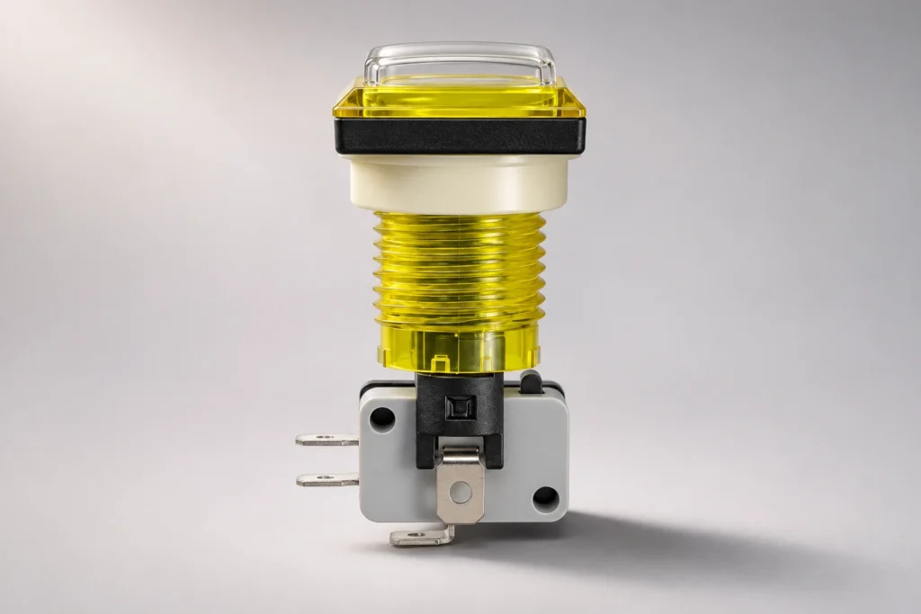
Push button clear cap abrasion haze is a surface and visibility issue that should be assessed separately from electrical switching life. Repeated contact, abrasive contamination or an unsuitable cleaning process may change the appearance of a transparent part, but a cloudy photograph alone does not identify the cause. For an OEM purchase, define the actual cap material and finish, the exposure to be evaluated, and the visibility requirement in the installed panel. This guide explains how to request and review evidence without inventing a universal haze limit, cleaning approval or abrasion rating for the Lemaele PBS series. Define the part and the visual task Start with the exact button configuration and its drawing. The Lemaele PBS series push button page is the product reference, and the selected product image shows a transparent top on a yellow assembly. That appearance does not establish its resin, coating or abrasion resistance. Confirm those characteristics for the ordered version instead of assigning a material from its color or clarity. Describe what the operator must see through or on the cap. The task may involve identifying a legend, distinguishing a state or recognizing the control among neighboring buttons. These tasks do not all impose the same visual requirement. Record the intended viewing distance and panel arrangement in the equipment review. If the control is illuminated, assess that configuration rather than assuming that an unlit cap sample represents it. Keep haze, scratches, dirt and color differences distinct Document the observed condition before naming the mechanism. A surface can look cloudy because of deposits, distributed fine damage or other changes requiring investigation. A distinct scratch is a different observation from a broad loss of clarity. Color variation...

Mehr lesen
Power Inlet Accessibility Test Finger: Review the Installed Equipment
Blog LEMA Electric

Power Inlet Accessibility Test Finger: Review the Installed Equipment

Power inlet accessibility test finger evidence should describe the protection offered by the finished equipment, using the probe and conditions required by the applicable product standard. A recessed connector opening, a current rating or a photograph does not establish that hazardous parts are inaccessible. For an OEM review, identify the inlet, its mounting and the equipment configuration before requesting a laboratory assessment. This guide explains what to ask and how to read the result. It does not prescribe a universal probe, test force or pass criterion for the Lemaele IPZ series, and it is not an instruction to insert objects into energized equipment. Begin with the equipment requirement Accessibility is a question about a person or object reaching a defined hazard through a particular opening. Start by identifying the finished product, intended users and applicable assessment requirements with the responsible compliance team. A mains connector mounted in one enclosure may present a different access path from the same connector mounted in another. The relevant assessment cannot be selected from the appearance of the inlet alone. The official IEC 61032 scope page describes probes used to verify enclosure protection against access to hazardous parts and entry of solid objects. That public summary identifies the subject of the standard; it does not provide the complete application rules for an IPZ installation. Obtain the applicable product standard and its referenced method through the team or laboratory responsible for the equipment assessment. Identify the supplied IPZ configuration The Lemaele IPZ series AC power socket is the product reference for this enquiry. Its family information and electrical characteristics do not establish a completed equipment accessibility result. Confirm the exact ordering code, mounting style, drawing revision...

Mehr lesen
Thermische Ermüdung von Lötverbindungen bei Mikroschaltern: Überprüfung der installierten Baugruppe
Blog LEMA Electric

Thermische Ermüdung von Lötverbindungen bei Mikroschaltern: Überprüfung der installierten Baugruppe

Die thermische Ermüdung von Lötverbindungen bei Mikroschaltern ist eine Frage der Zuverlässigkeit der Baugruppe: Wiederholte Temperaturänderungen können eine Lötverbindung belasten, wenn sich die miteinander verbundenen Teile unterschiedlich ausdehnen. Die mechanische Lebensdauer eines Schalters gibt keinen Aufschluss über die Lebensdauer seiner eingebauten Lötverbindungen. Um das Risiko zu bewerten, müssen die tatsächliche Anschluss- und Lötstellenkonstruktion identifiziert, die thermische Vorgeschichte des Geräts beschrieben und ein Prüf- und Inspektionsplan für die fertige Baugruppe abgestimmt werden. Dieser Leitfaden unterstützt OEM-Teams dabei, aussagekräftige Nachweise für eine KW7-Installation anzufordern. Er sagt weder eine bestimmte Anzahl von Ausfallzyklen voraus noch schreibt er ein Temperaturprofil vor oder behauptet, dass NASA-Forschung ein Produkt von Lemaele qualifiziert. Lötbarkeit der Anschlüsse, prozessbedingte Schäden und Ermüdung getrennt betrachten Bei der Lötbarkeit geht es darum, ob die Oberfläche des Anschlusses unter dem freigegebenen Prozess eine geeignete Lötverbindung bilden kann. Prozessbedingte Schäden betreffen Vorgänge während der Herstellung der Lötverbindung, einschließlich ungeeigneter Erwärmung oder mechanischer Belastung. Die thermische Ermüdung betrifft hingegen die im Anschluss an die Montage durch wiederholte Temperaturänderungen verursachten kumulativen Schäden. Diese Fragestellungen können miteinander zusammenhängen, sind jedoch nicht gleichzusetzen. Ein erfolgreicher Benetzungstest weist keine jahrelange Einsatzdauer im Feld nach, und ein Riss im Feldeinsatz lässt für sich genommen nicht auf die ursprüngliche Fertigungsursache schließen. Verwenden Sie den Leitfaden zur Lötbarkeit von Anschlüssen nach der Lagerung, um Nachweise zum Oberflächenzustand bei Wareneingang zu erhalten. Verwenden Sie den Leitfaden zu Lötvorkehrungen bei Mikroschaltern für die Überprüfung des Fertigungsprozesses. Hier liegt der gesonderte Schwerpunkt auf der Verbindung nach dem Einbau und der wiederholten thermischen Belastung. Durch diese Unterscheidung wird verhindert, dass ein Einkaufsteam ein Prozesszertifikat als Nachweis für eine Anforderung an die Lebensdauer im Einsatz akzeptiert, die damit nie geprüft wurde. Was die verfügbaren Forschungsergebnisse belegen Die Veröffentlichung von Sandia zur Zuverlässigkeit von Lötverbindungen identifiziert die thermomechanische Ermüdung als einen Mechanismus, der mit Temperaturwechseln und unterschiedlichen Wärmeausdehnungen innerhalb des Verbindungssystems zusammenhängt. Dies spricht dafür, die verbundenen Materialien und ihre mechanischen Randbedingungen gemeinsam zu untersuchen. Dies...

Mehr lesen
Installation des Fußschalterkabels bei Kaltbiegebeanspruchung: Einhaltung der zulässigen Handhabungsgrenzen bestätigen
Blog LEMA Electric

Installation des Fußschalterkabels bei Kaltbiegebeanspruchung: Einhaltung der zulässigen Handhabungsgrenzen bestätigen

Die Installation des Kabels eines Fußschalters bei kalten Temperaturen und mit engen Biegungen erfordert spezifische Handhabungsvorgaben für das jeweilige Kabel. Die Betriebstemperatur eines Pedals gibt nicht an, bei welcher Temperatur sein Kabel sicher abgewickelt, gebogen oder verlegt werden kann. Bevor Sie eine Montage bei niedrigen Temperaturen durchführen, identifizieren Sie das tatsächliche Kabel, beschaffen Sie Angaben zur Mindestinstallationstemperatur und zu den Biegevorschriften und stellen Sie sicher, dass die geplante Verlegung diese Anforderungen erfüllt. Biegen Sie ein steifes Kabel nicht gewaltsam um eine Kante, nur weil das Gehäuse des Fußschalters für den Raum geeignet erscheint. Dieser Leitfaden unterstützt Käufer und Installateure von Geräten bei der Vorbereitung dieser Entscheidung, ohne einen universellen Temperaturwert, eine Aufwärmzeit oder einen Biegeradius für die Lemaele-LF-Serie zu erfinden. Unterscheiden Sie zwischen Kälte im Betrieb und Kälte bei der Handhabung. Ein fest installiertes Kabel in einer laufenden Maschine und ein Kabel, das in eine neue Verlegung eingezogen wird, sind unterschiedlichen mechanischen Bedingungen ausgesetzt. Der Installateur muss das Kabel möglicherweise abwickeln, um eine Ecke führen, durch eine Öffnung ziehen und in der Nähe des Kabeleingangs am Fußschalter befestigen. Jede dieser Handlungen kann Biegungen oder Zugbelastungen verursachen. Eine Angabe zur Temperaturbeständigkeit bei niedrigen Temperaturen muss daher immer im Zusammenhang mit den genannten Prüf- und Einsatzbedingungen betrachtet werden. Ein aufgedruckter Temperaturwert auf einem Kabel stellt noch keine vollständige Installationsanweisung dar. Beginnen Sie bei einer LF-Baugruppe mit der tatsächlich gelieferten Konfiguration. Die Produktseite der Fußschalter der Lemaele-LF-Serie beschreibt die Produktfamilie und weist auf individuell anpassbare Verdrahtungen hin. Sie legt jedoch weder einen einheitlichen Kabelwerkstoff noch eine einheitliche Konstruktion oder Mindesttemperatur für die Handhabung bei allen Bestellungen fest. Fragen Sie nach der Kabelidentifikation, die dem Kaufauftrag und der Montagezeichnung zugeordnet ist. Versuchen Sie nicht, das Mantelmaterial anhand seiner schwarzen Farbe oder seines Flexibilitätsgefühls in Innenräumen zu bestimmen. Warum die Steifigkeit bei niedrigen Temperaturen besondere Aufmerksamkeit verdient: Die Temperatur kann das Verhalten eines Polymers unter Belastung verändern. Die Erklärung des MIT zur Kältesprödigkeit beschreibt, wie eine eingeschränkte Molekülbeweglichkeit die Duktilität verringern kann, indem sie in ...

Mehr lesen