CENTRO DE NOTÍCIAS LEMA

Notícias e Blog

Centro de Notícias

Limit Switch Housing Coating Adhesion: Specify Useful Inspection Evidence
Blog LEMA Electric

Limit Switch Housing Coating Adhesion: Specify Useful Inspection Evidence

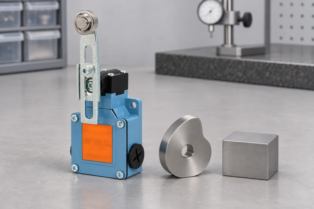
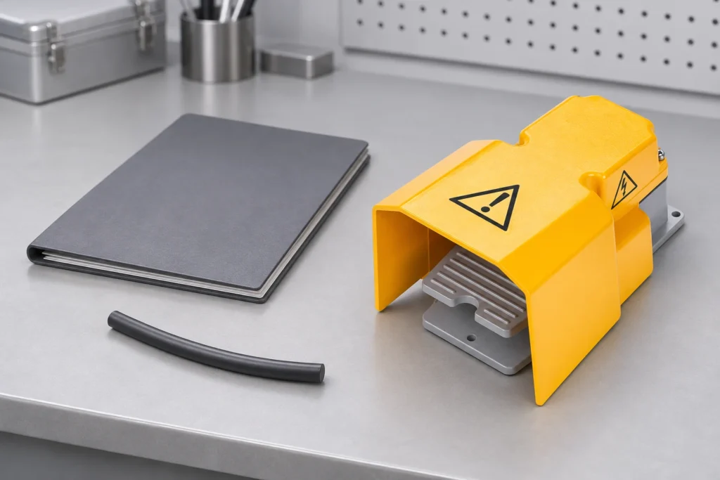
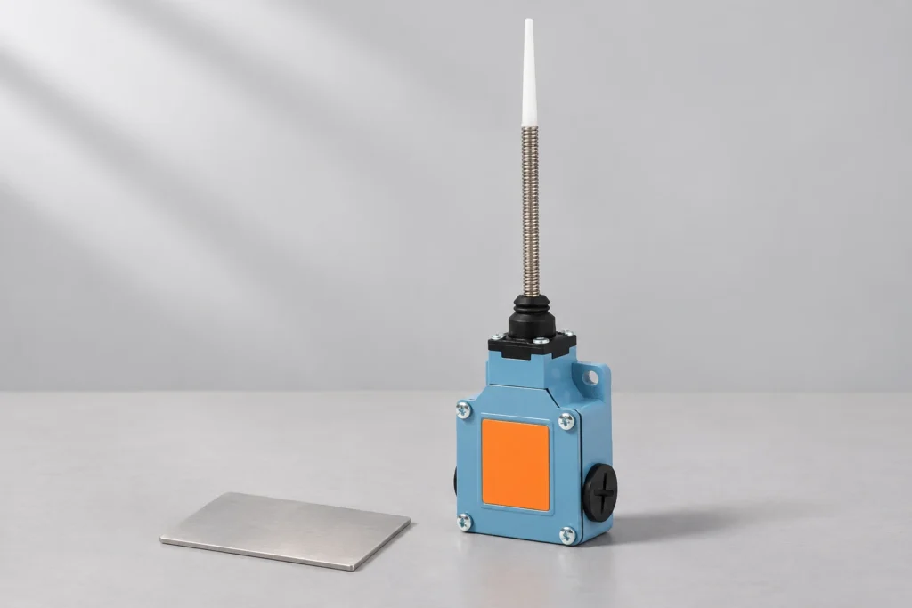
Limit switch housing coating adhesion evidence should identify the actual substrate, coating system, test specimen and method before a buyer accepts a result. A good-looking finish does not prove attachment, and a tape-test rating does not establish corrosion life or enclosure sealing. For an LZ1 series inquiry, confirm the selected housing finish and the requirement that the evidence must answer. This guide helps OEM buyers request interpretable coating records without damaging installed equipment or borrowing unrelated acceptance limits. It establishes no Lemaele coating chemistry, mandatory adhesion class, test approval or environmental performance claim.Confirm which housing and finish the report coversUse the LZ1 series limit switch product page to identify the relevant product family, then confirm the ordered version and drawing with the supplier. A blue housing in a photograph does not identify the coating chemistry, preparation process or layer structure. Request the controlled finish description for the actual order before choosing a test method.Identify the surface of interest. The main enclosure, removable cover, mounting ears, screws and actuator assembly may not share one finish or substrate. A result from one of those surfaces should not be relabelled as a result for every exposed part. Mark the location on a drawing or photograph and retain the connection between that location and the reported specimen.The heavy-duty limit switch selection guide covers the broader sourcing decision. Keep actuator arrangement, electrical configuration, mounting and operating environment in the specification. Coating attachment is a useful quality question within that decision. It cannot replace evidence that the selected switch version meets the functional and installation requirements of the machine.Separate visible condition from adhesion evidenceInspect and photograph the as-received finish before any destructive work. Record chips, scratches,...

Ler mais
Foot Switch Cable Jacket Durometer: Read Hardness Reports Correctly
Blog LEMA Electric

Foot Switch Cable Jacket Durometer: Read Hardness Reports Correctly

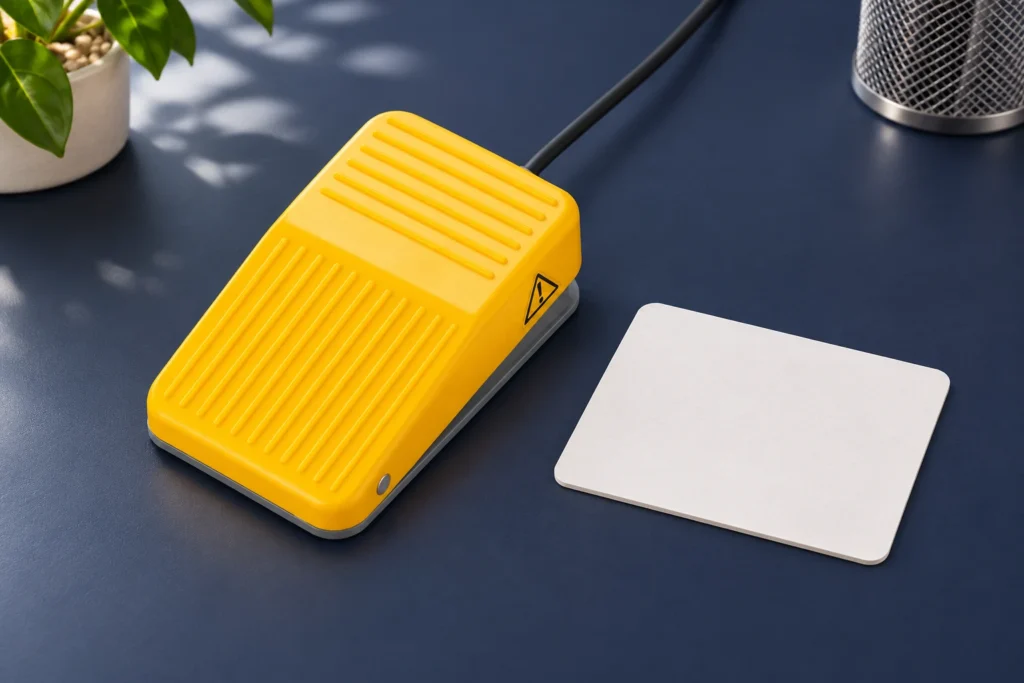
Foot switch cable jacket durometer evidence is useful only when the report identifies the material, specimen, hardness scale and measurement conditions. A bare number does not prove that a cable is flexible enough for repeated pedal movement or suitable for a particular machine. For an LF series inquiry, first confirm the ordered cable construction and ask how the tested specimen represents it. This guide explains how OEM buyers can review hardness information without mistaking a material result for complete cable qualification. It provides no assumed LF jacket polymer, Shore target, approved test setup or service-life prediction.Start with the cable actually being purchasedThe LF series foot switch product page is the product reference for this inquiry. Confirm whether the requested order includes a cable, its controlled construction identifier and the applicable drawing revision. A catalogue photograph cannot identify the polymer formulation or prove that every offered wiring configuration uses the same jacket. Obtain the information for the version being quoted.Explain why you need hardness information. You may be comparing approved incoming material, investigating a noticeably changed jacket feel or documenting a specified cable construction. Those questions require traceable comparisons. They do not justify choosing an arbitrary hardness target and asking the supplier to match it. Start with the application requirement and the evidence already available for the selected construction.The electric foot switch selection guide places the cable question within the wider control selection. Keep the pedal, contacts, enclosure, connection and machine application in scope. A good material report cannot compensate for an unsuitable electrical configuration or installation. Record who owns cable approval and who approves the complete control for the equipment.Read the scale with the numberDurometer hardness describes resistance to a...

Ler mais
Push Button Cap Sink Marks: A Practical Incoming Inspection Guide
Blog LEMA Electric

Push Button Cap Sink Marks: A Practical Incoming Inspection Guide

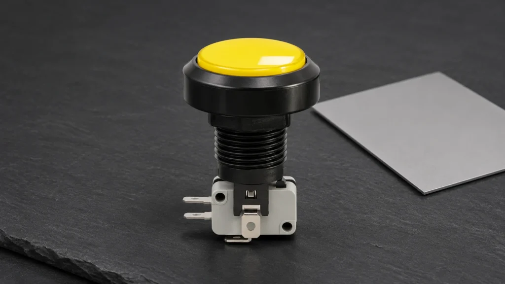
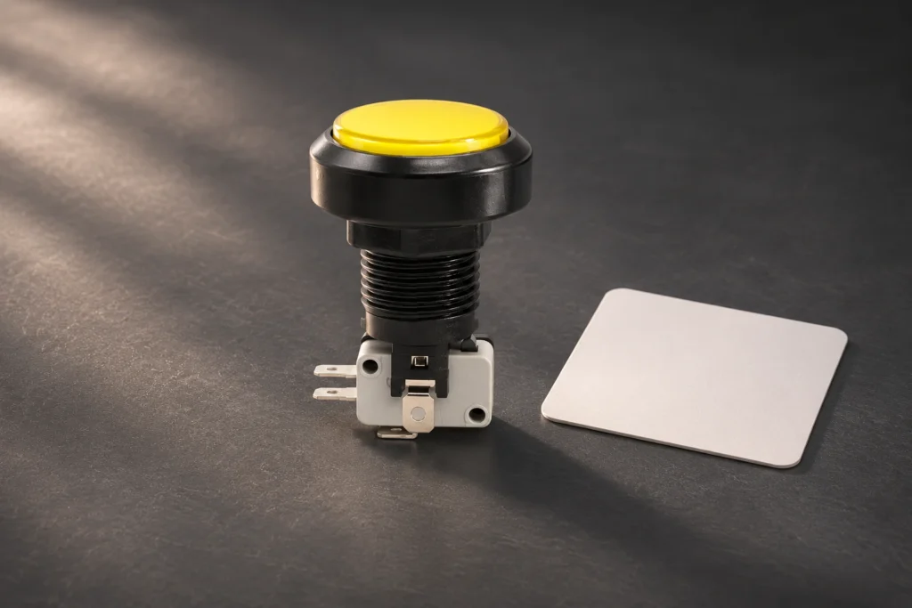
Push button cap sink mark inspection begins with a controlled comparison of the actual cap surface, an approved reference and the agreed cosmetic requirement. A suspected sink mark is a local depression; a dark reflection alone does not establish a depression or its manufacturing cause. Record the location, viewing conditions and sample identity before deciding whether measurement or supplier investigation is needed. This guide gives OEM buyers an inspection workflow for a PBS series inquiry. It does not claim that a pictured PBS product has a defect, identify its resin or prescribe a universal permissible sink depth.Identify the cap and the surface that mattersStart with the exact configuration on the order. The PBS series push button switch page identifies the relevant Lemaele family, but a family image cannot replace the approved cap drawing or cosmetic reference. Confirm cap colour, shape, operating face and revision. Compare the delivered version with the same version, since differences between designs may be intentional.Define the inspection zone on a photograph or drawing. An operator-visible cap face may have a different cosmetic requirement from a concealed underside. State whether the bezel is included. Keep a moulded depression distinct from an intentional recess, lettering feature or curved profile. An inspector should not have to guess which surfaces the purchasing agreement treats as appearance-critical.Use the industrial push button selection guide for the wider selection decisions. Appearance review is one part of that process. Contact arrangement, mounting fit and application suitability need their own records. A cosmetic approval should never silently become approval of the complete control or permission to omit the functional checks required by the equipment design.Make a suspected depression repeatably visibleInspect the reference and suspect sample...

Ler mais
Micro Switch Mounting Hole Position: Inspect Against the Correct Drawing
Blog LEMA Electric

Micro Switch Mounting Hole Position: Inspect Against the Correct Drawing

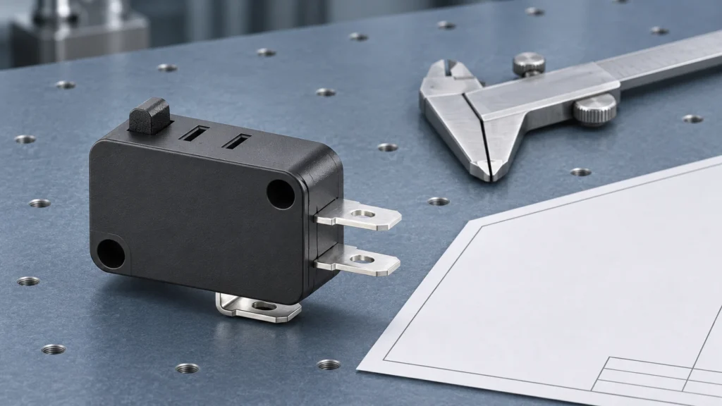
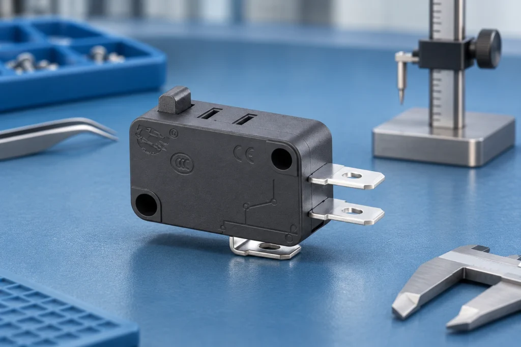
Micro switch mounting hole position inspection begins with the selected part drawing, its reference features and the requirement being checked. Identify the housing version before measuring, distinguish hole size from hole location, and use a method that can evaluate the specified relationship without distorting the switch. A successful screw insertion or one centre-spacing measurement does not prove every positional requirement. For an OEM purchase, request a report tied to the actual part and drawing revision. This guide uses the KW7 family as a product reference, while establishing no universal hole spacing, positional tolerance, datum scheme or mounting torque for that family.Identify the ordered housing and drawing firstThe Lemaele KW7 series product page shows the family relevant to this inspection. Confirm the exact actuator, terminal and housing configuration with the ordering record. Similar switches can share a general silhouette while differing in mounting or operating geometry. Use the supplier-approved drawing for the actual configuration rather than measurements taken from a catalog photograph.Check units and drawing revision before comparing the part with a bracket or replacement component. Keep an overall photograph and a specimen identifier with the inspection request. The KW7 product selection guide provides surrounding product context, but a general guide is not a substitute for the controlled drawing that defines the order.Write down the immediate decision: incoming dimensional acceptance, an assembly-fit investigation or approval of a replacement. These are related tasks with different evidence needs. A report suitable for screening a shipment may not explain a machine alignment problem, while a successful trial assembly may leave the contractual dimensional requirement unassessed.Separate hole diameter, spacing and positionHole diameter describes a size characteristic. Spacing describes a relationship between identified features. Position may...

Ler mais
Power Inlet Housing Water Absorption: Review the Right Material Evidence
Blog LEMA Electric

Power Inlet Housing Water Absorption: Review the Right Material Evidence

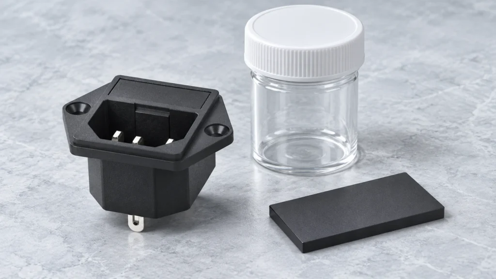
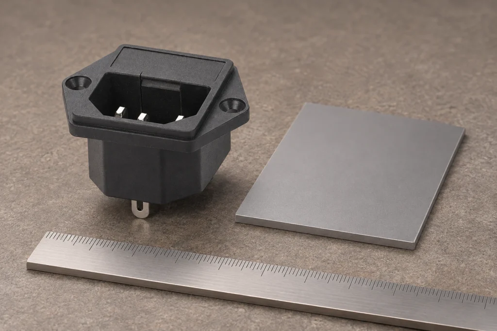
Power inlet housing water absorption evidence should identify the actual material, specimen and exposure conditions before a buyer compares any reported value. A generic polymer datasheet does not establish the behaviour of an unidentified finished inlet, and low material water uptake does not prove a waterproof assembly. Ask what was tested, how it relates to the supplied configuration and which application decision the report supports. This guide helps equipment buyers review those records for an IPZ series inquiry. It does not identify the IPZ housing resin, prescribe an immersion test for an assembled inlet or establish an electrical safety approval.Identify the material behind the requested evidenceStart with the selected component and current ordering record. The Lemaele IPZ series AC power socket is the product reference here. Confirm the mounting version, drawing revision and controlled housing material identifier with the supplier. Similar-looking black housings can have different formulations; appearance alone is not a material identification method.Ask whether the material designation applies to the supplied production or to an earlier development sample. If a compound has fillers, colourants or a controlled grade suffix, retain the full identifier needed to connect its evidence to the order. Where detailed formulation is confidential, agree which supplier declaration and traceable identifier will answer the purchasing question.Write down why water uptake matters to the equipment project. The concern could involve dimensional stability, material comparison or a request from the responsible compliance engineer. These questions should not be collapsed into a vague demand for a waterproof certificate. A clear purpose helps the supplier provide relevant evidence instead of an unrelated material brochure.Separate absorption data from water content and sealingWater absorption describes uptake under defined exposure conditions. A water-content...

Ler mais
Push Button Cap Gloss Inspection: Compare Appearance Consistently
Blog LEMA Electric

Push Button Cap Gloss Inspection: Compare Appearance Consistently

Push button cap specular gloss inspection needs an agreed reference, a defined viewing or measurement method, and identification of the exact cap being assessed. Compare clean, identified samples under consistent conditions before deciding whether an appearance difference is a production issue. A numerical gloss result is useful only when the instrument and specimen are suitable for the comparison. Do not accept or reject a curved button cap using an unexplained number from a flat material plaque. This guide helps OEM buyers specify the evidence they need; it establishes no universal gloss limit or particular resin for Lemaele PBS caps.Define the appearance question before ordering a testGloss is the subject of this inspection, rather than cap colour consistency, scratches or electrical operation. A cap may look different because of the lighting, its orientation or a change in surface condition. Describe the complaint with identified samples and photographs before assigning a cause. Ask whether the purchase requirement concerns a visual match or an instrumental quantity. Those decisions can require different evidence.The PBS series push button product page provides the product family for this discussion. Confirm the selected cap shape, colour, finish and ordering configuration with Lemaele. A family photograph is not a material declaration or approved appearance master. The industrial push button selection guide covers the broader application decisions surrounding that choice.Identify the user-visible surface. The centre of the operating face, a rounded edge and the surrounding bezel can present different geometries. Do not combine observations from these surfaces into one unexplained verdict. Mark the inspection region on a reference photograph and state which areas are excluded, such as the threaded mounting body or the underside contact assembly.Use the same conditions for...

Ler mais
Power Inlet Molding Shrinkage: Request Finished-Part Dimensional Evidence
Blog LEMA Electric

Power Inlet Molding Shrinkage: Request Finished-Part Dimensional Evidence

Power inlet molding shrinkage dimensional evidence should connect the identified material and production process to measurements of the finished inlet housing. A resin datasheet value is useful background, but it does not prove that a delivered flange, cavity or mounting feature meets its drawing. Request the selected inlet configuration, material identification, controlled dimensions and representative inspection records. Keep material-specimen shrinkage separate from actual component acceptance and from panel fit. This guide helps OEM buyers ask for relevant evidence; it does not identify the IPZ housing polymer, specify a shrinkage percentage or infer dimensional conformity from a catalog image.Separate material data from the component requirementThe finished housing is the purchasing subject. A material test specimen is a different object made under its own defined conditions. Start by listing the inlet features that matter to the intended assembly, using the supplier drawing and the equipment design. Do not turn every available resin property into an acceptance requirement without an application reason.The IPZ Series AC Power Socket is the relevant family reference. Confirm the exact mounting version and supplied drawing because the family image includes different mounting arrangements. The snap-in versus screw-mount inlet guide explains that selection boundary. This article concerns dimensional evidence from molding, rather than choosing the mounting system.Ask the supplier to identify the housing material under the applicable disclosure arrangement. Do not presume a polymer from color, hardness by touch or an unrelated product in the same catalog. Where detailed formulation is confidential, agree which controlled material identifier and conformity record are sufficient for the order.Understand what a shrinkage standard can establishThe public scope of ASTM D955 concerns shrinkage measurements on molded thermoplastic specimens. It expressly limits transferring those specimen...

Ler mais
Micro Switch Terminal Coplanarity: Verify the Drawing Before Measuring
Blog LEMA Electric

Micro Switch Terminal Coplanarity: Verify the Drawing Before Measuring

Micro switch terminal coplanarity inspection is useful only when the selected terminal configuration and assembly drawing define which surfaces should share a plane. First confirm the switch variant, intended connection and reference features. Then measure the specified terminal locations using a method that does not bend them into an apparent pass. Spade tabs, solder terminals and board-mount leads should not inherit the same assumed requirement. For an OEM order, request the controlled terminal drawing and acceptance criteria before buying a generic coplanarity test. This guide explains how to organize that evidence without inventing a KW7 tolerance or treating every microswitch as a surface-mount component.Confirm that coplanarity is the actual assembly concernTerminal position relative to an intended common plane is separate from terminal strength, solderability and contact resistance. Identify the assembly feature that needs alignment. A harness using individual receptacles may have a different concern from a rigid board interface. Do not choose the test merely because the terminal ends look uneven in a perspective photograph.The KW7 Series Micro Switch KW7-0 Black Switch with CE CQC presents a family with different actuator and terminal options. Confirm the purchased version with the supplier rather than treating one catalog image as a complete dimensional drawing. The micro switch terminal types guide helps organize those connection choices before a dimensional review.If the assembly interference is actually caused by terminal spacing, angle or clearance, call it that. A coplanarity report may not capture those characteristics. Mark the specific contact region or lead feature on the approved drawing and explain how it interacts with the mating part. The inspection request should answer that interface question.Establish the reference before collecting heightsAsk which features locate the switch in...

Ler mais
Toggle Switch Handle Surface Roughness: Define a Repeatable Inspection
Blog LEMA Electric

Toggle Switch Handle Surface Roughness: Define a Repeatable Inspection

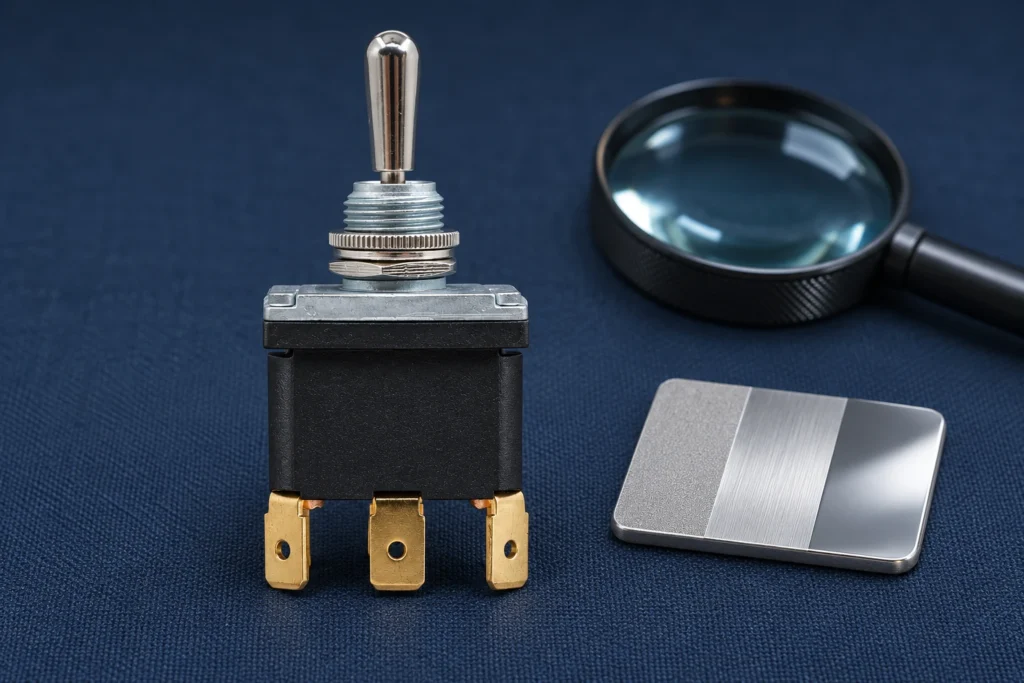
Toggle switch handle surface roughness inspection should begin with a defined surface, an agreed finish requirement and a method that can examine the curved handle without damaging it. A shiny appearance or a smooth feel does not establish a numerical roughness value. Separate visible burrs and coating defects from measured texture, then compare each finding with the approved drawing or sample. For an OEM purchase, ask which handle variant and finish were supplied before requesting a test. This guide organizes that inspection and its records; it does not prescribe a universal roughness limit or claim a particular finish for every Lemaele toggle switch.Identify the handle surface covered by the requirementThe user-contact handle surface is a different inspection subject from the mounting thread, pivot mechanism or electrical contacts. Define whether the requirement covers the rounded tip, the sides, a seam, or another identified region. A result from an easy-to-reach patch cannot automatically represent the entire handle. Include an annotated drawing or photograph that identifies the area without concealing it with labels.The LT3230C Spade Terminal Heavy Duty Toggle Switch DPDT ON-OFF-ON provides a concrete product reference for the inquiry. Use the selected ordering configuration and current drawing to confirm the handle geometry and finish. Do not infer a coating material, roughness value or polishing process from the product photograph. The broader metal toggle switch selection guide addresses the surrounding purchasing decisions.Ask why surface condition matters in the application. A cosmetic match, comfortable manual contact, resistance to snagging and a controlled manufacturing finish can require different evidence. Translate the actual concern into an inspectable requirement. A single roughness number may not describe a sharp isolated edge or a visible scratch that matters to...

Ler mais
Limit Switch Cam Target Hardness: Ask for Evidence Before Specifying a Value
Blog LEMA Electric

Limit Switch Cam Target Hardness: Ask for Evidence Before Specifying a Value

Limit switch cam target surface hardness evidence should identify the separate mating cam, its material and condition, the test method and scale, and the locations actually tested. A bare hardness number is not enough to approve the interface. Confirm whether the result concerns the working surface, an underlying region or a representative coupon. Then review it together with cam shape, alignment and application conditions. No universal hardness value can be assigned to every roller limit switch, and a harder target does not by itself demonstrate longer switch life or acceptable operation.Identify the part that the hardness report describesThe cam or dog is the external machine part that actuates the switch. The roller, lever and switch housing are different components. A hardness certificate for the cam stock does not establish the roller material or the switch’s durability. Begin the review by placing the cam drawing and switch ordering information beside the report, with each component identified separately.The Lemaele LZ1 series product page supplies product-family information, but it does not prescribe the material or surface hardness of every customer-designed cam. Request application guidance for the selected actuator and use the machine designer’s controlled cam drawing. Do not infer a target hardness from the visible silver roller or the switch housing description.This is an evidence review for an existing or proposed mating part. For the overall actuator choice, begin with the limit switch actuator types guide. For the shape and travel of the target, use the separate cam profile design review. Those decisions remain necessary even when the hardness documentation is complete.LZ1 roller lever limit switch beside a separate unattached cam target coupon. Product-reference illustration; not a test result or approved test fixture.Read...

Ler mais
Power Inlet Mounting Flange Flatness: Inspect Seating Before Tightening
Blog LEMA Electric

Power Inlet Mounting Flange Flatness: Inspect Seating Before Tightening

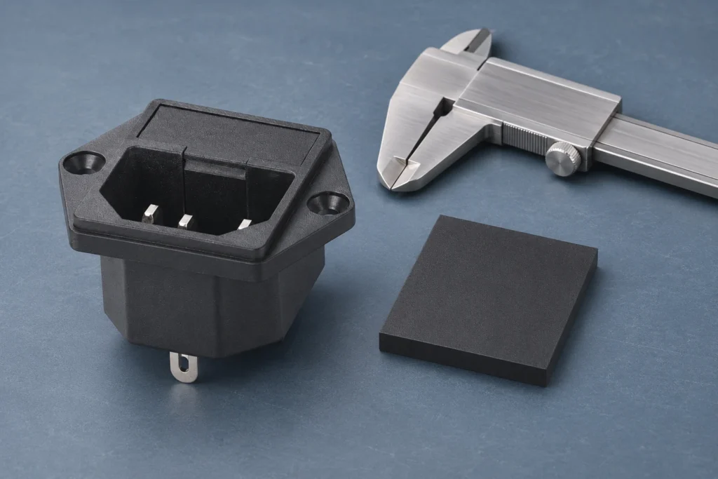
Power inlet mounting flange flatness inspection begins by identifying the intended seating surface and the condition in which it must be checked. Examine the loose inlet and panel separately before tightening screws. Remove only permitted loose contamination, record rocking or visible gaps, and compare measurements with the approved drawing and agreed method. A flange that pulls down when screws are tightened has not automatically passed a flatness check. The assembly may be deforming to match the panel. Distinguish the inlet’s own form from panel distortion, surface obstruction and the fit of the complete mounted equipment.Decide whether you are checking form or assembled fitFlatness concerns the form of a defined surface. Seating concerns how two real parts contact in a particular arrangement. These questions overlap, but they are not interchangeable. A flat flange can sit poorly on a distorted panel, and an uneven flange can appear flush after forced assembly. State which question the inspection is intended to answer before selecting a fixture.A mounting flange may contain ribs, recessed regions, molded features or local contact pads. Do not treat every visible exterior face as the intended mounting plane. Obtain the supplier drawing and identify the functional seating regions. If the drawing does not specify a flatness requirement, ask for the relevant assembly acceptance criteria rather than inventing a numerical limit.The IPZ series product page shows mounting variants. Confirm the exact screw-mount version before planning a flange check. A snap-in body has a different retention interface, so a procedure developed for screw ears should not be transferred without review. The mounting style comparison helps distinguish those interfaces.Close view of IPZ inlet flange seating edge beside an unattached panel sample. Product-reference illustration; not...

Ler mais
Foot Switch Cable Conductor Strand Verification: Check the Ordered Construction
Blog LEMA Electric

Foot Switch Cable Conductor Strand Verification: Check the Ordered Construction

Foot switch cable conductor strand verification starts with the approved cable construction, not with how flexible the finished cord feels. Match the ordered cable part number and revision to supplier records, identify the conductor material and declared stranding, and use a traceable sacrificial sample when a physical examination is required. Record which conductor was examined and how the sample was prepared. A continuity reading can support an electrical check, but it does not identify the number or condition of individual strands. Keep construction acceptance separate from bend-life qualification, terminal approval and the safety assessment of the finished machine.Define the cable being purchased before counting strandsA purchasing description such as “flexible black cable” leaves important questions unanswered. Request the cable manufacturer or controlled supplier code, conductor count, nominal conductor size, insulation and jacket identification, and the drawing revision supplied with the foot switch. If stranding matters to the design, ask for the declared construction and its permitted variation. Do not infer these details from an outer diameter, a photograph or a general product family name.The Lemaele LF series product page describes customizable wiring. It does not establish one universal strand count or cable compound for every delivered configuration. Use the selected LF ordering record to connect the approved cable to the actual pedal assembly. This article concerns that identification task; the foot switch selection guide covers the wider application review.Separate the individual conductor from the complete cable. A multicore cable can contain several insulated conductors, each containing multiple metal strands. A braid or shield is another construction feature and should not be counted as a power conductor. Photograph the sample with identifiers that make this distinction clear, especially when a supplier...

Ler mais