LEMA NEWS CENTER

News & Blog

News Center

Center-Off Toggle Switch: ON-OFF-ON Circuit Uses
Blog LEMA Electric

Center-Off Toggle Switch: ON-OFF-ON Circuit Uses

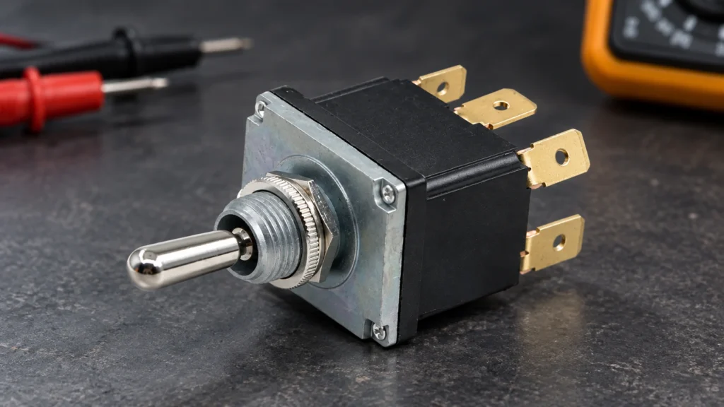
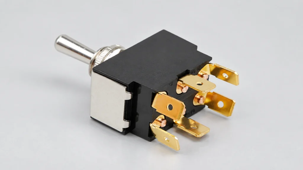
A center-off toggle switch has three stable lever positions—ON, OFF and ON—so the middle position disconnects the controlled path while either outer position selects a different circuit state. It is commonly used for forward/stop/reverse requests, raise/stop/lower controls, source selection and manual mode commands. The label describes lever behavior, not the internal terminal map. Pole count, maintained or momentary action, contact sequence, voltage, load and interlocking must all be verified before wiring. This guide explains how to specify an ON-OFF-ON switch without confusing it with ON-ON-ON or momentary variants. LEMA LT3130A images are real product references. Always use the exact model drawing and continuity table for the selected ordering code. Center-off patterns compared MarkingCenter stateOuter positionsTypical use ON-OFF-ONMaintained open/neutral stateTwo maintained selectionsDirection or source selection with a stop position (ON)-OFF-(ON)Maintained centerMomentary both sidesRaise/lower or jog commands (ON)-OFF-ONMaintained centerOne momentary, one maintainedMixed command functions after risk review ON-ON-ONConnected center patternTwo additional connected patternsMulti-circuit selection; not center-off ON-OFFNo third positionOne connected, one disconnectedSimple two-position control Parentheses conventionally indicate spring-return positions, but markings vary. Confirm the mechanical action and circuit diagram instead of ordering from punctuation alone. What happens in the center position In a true center-off function, the relevant moving contact is not connected to either outer throw in the center position. In a single-pole version, a common terminal usually selects one of two throws. In a double-pole version, two independent commons change together. The center may disconnect both poles, but terminal numbering and physical layout differ between families. Center-off does not guarantee galvanic isolation for every circuit or a safety-rated stop. Contact spacing, leakage through other components, shared commons and downstream electronics still matter. If isolation or hazardous-motion stopping is required, use...

Read More
Limit Switch Mounting Position and Repeatability Guide
Blog LEMA Electric

Limit Switch Mounting Position and Repeatability Guide

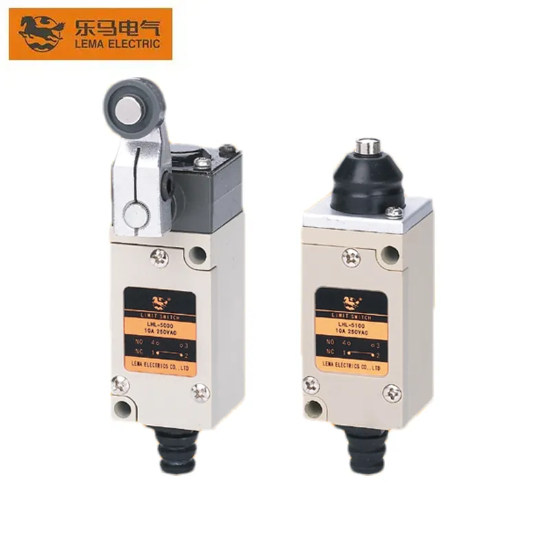
Correct limit switch mounting places the actuator where the machine target reaches the operating point consistently, travels far enough to create margin, and stops before the switch is mechanically overloaded. Repeatability depends on the complete system: bracket stiffness, target geometry, approach direction, speed, actuator type, bearing play, temperature, contamination and electrical response. A precise switch on a flexible bracket will not produce a precise machine reference. This guide gives an OEM mounting and validation process using LEMA HL-series products as real visual references. Product photos show the physical family only. Confirm the exact operating position, movement differential, overtravel, allowable force, approach angle and enclosure data from the controlled model drawing. Mounting decisions at a glance DecisionPreferred practiceRisk if ignoredVerification BracketRigid, located by repeatable datumsPosition drift and vibrationDeflection check and torque record ApproachFollow permitted actuator directionSide load, impact or lever damageSlow-motion observation Operating marginTarget passes operating point without exceeding limitIntermittent actuation or overtravelWorst-case tolerance test Target surfaceSmooth, durable and correctly profiledWear, bounce and inconsistent releaseInspection after cycling CableSupported with strain relief and service loopTerminal load or water pathPull and routing inspection Machine referenceDefined independently of switch housingUncontrolled calibration changesGauge or fixture measurement Define what “repeatability” means Repeatability is the spread of switching positions when the same mechanism approaches under the same conditions. It is not the same as absolute accuracy. A switch can repeat closely but actuate at an offset from the desired machine coordinate. A system may also change with approach direction because mechanical backlash, lever friction and movement differential create hysteresis. Write an acceptance statement with units and test conditions. For example: “input changes state within the approved position band during ten forward approaches at production speed and releases...

Read More
Micro Switch for Inductive Loads: Rating and Protection Guide
Blog LEMA Electric

Micro Switch for Inductive Loads: Rating and Protection Guide

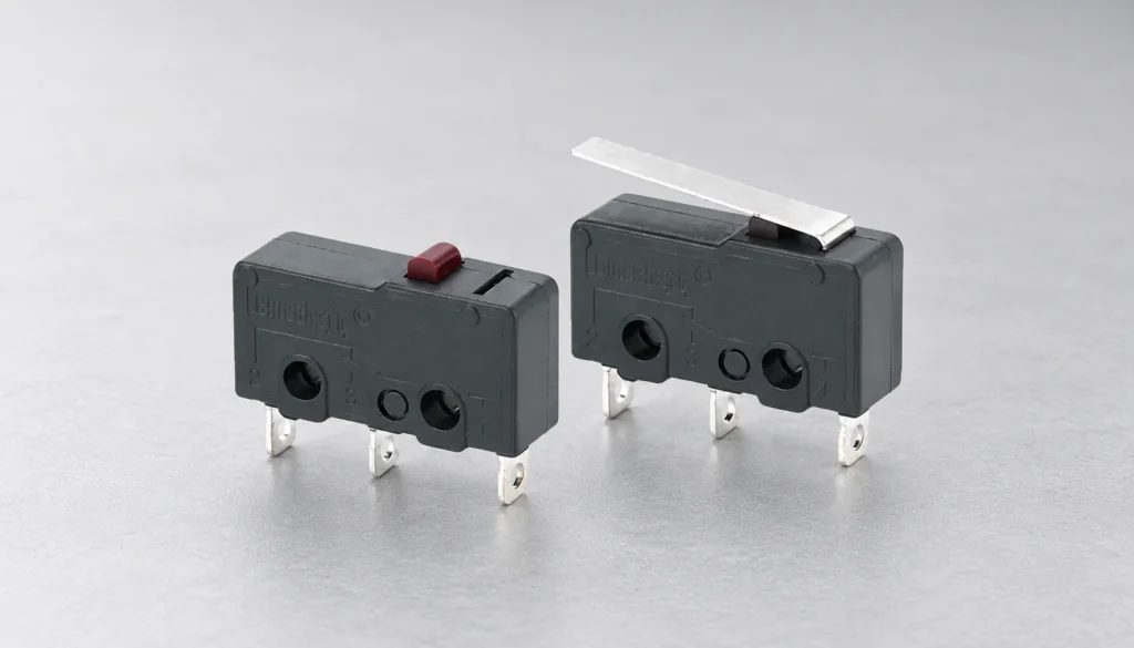
A micro switch for an inductive load must be selected from the load’s making and breaking behavior, not from a resistive current number alone. Solenoids, relays, contactors and small motors can draw inrush current and create a voltage spike when the circuit opens. Those effects can erode or weld contacts, produce electrical noise and shorten service life. The safe method is to identify the actual load, check the exact switch rating for that load category, keep margin, and use a suitable suppression or interface device when the switch data does not directly cover the duty. This guide explains the engineering questions behind that choice. LEMA KW12-series images are used as real product references, but the photographed appearance does not prove a particular inductive-load rating. Confirm the ordering code, datasheet, circuit voltage, current, operating rate and environmental conditions before approval. Why an inductive load is harder on contacts An energized coil stores energy in its magnetic field. When a mechanical contact opens, current tries to continue flowing. The resulting voltage across the opening gap can create an arc. At closing, a motor or transformer may also draw a current higher than its steady-state value. A switch that carries a small resistive heater current comfortably can therefore fail early when used at the same nameplate current with a coil or motor. The problem is not solved by looking only at watts. AC and DC arcs behave differently, coil time constants differ, and the contact material, gap, speed and enclosure all affect interruption. Treat “inductive” as a prompt to obtain the exact switching category and test conditions rather than as a universal derating percentage. Selection table for common inductive duties LoadMain stressInformation requiredTypical...

Read More
AC Power Inlet Fuse Sizing for OEM Equipment
Blog LEMA Electric

AC Power Inlet Fuse Sizing for OEM Equipment

An AC power inlet fuse cannot be selected from the inlet current rating or appliance wattage alone. Start with the equipment’s maximum steady input current at the lowest permitted supply voltage, then evaluate startup inrush, abnormal-load behavior, conductor capacity, fuse time-current curve, voltage rating, breaking capacity, ambient temperature, holder rating and applicable equipment standard. The selected fuse must carry normal operation without nuisance opening while interrupting defined faults safely. A licensed or otherwise qualified designer must confirm the final protective scheme. This guide provides an OEM selection process for a fused AC inlet. It does not prescribe a universal multiplier or a fuse value for a specific machine. LEMA IPZ-series images are product references only; the exact inlet, fuse holder and fuse must be checked as a coordinated assembly. Inputs required before choosing a fuse Design inputWhy it mattersEvidence to collect Supply voltage and frequency rangeChanges operating current and must remain within fuse voltage ratingEquipment input specification Maximum steady input currentEstablishes the normal thermal loadWorst-case measurement and calculation Startup or inrush waveformMay open a fast fuse despite acceptable steady currentPeak current, duration, repetition and temperature Fault current availableMust not exceed the fuse’s interrupting capabilityInstallation or supply-system study Internal conductor and component limitsThe fuse must protect the intended weak pointsWire, PCB, switch, filter and load ratings Ambient and enclosure temperatureChanges fuse carrying capacity and holder heatingWorst-case thermal test Applicable standard and approvalDefines construction, spacing, testing and replacement markingCompliance plan and certified component records If any of these inputs is unknown, the correct action is to measure or obtain it, not to increase the fuse rating until nuisance opening stops. An oversized fuse may leave the cord, inlet, switch, filter or internal...

Read More
Push Button Switch Symbols: NO, NC and Illuminated Types
Blog LEMA Electric

Push Button Switch Symbols: NO, NC and Illuminated Types

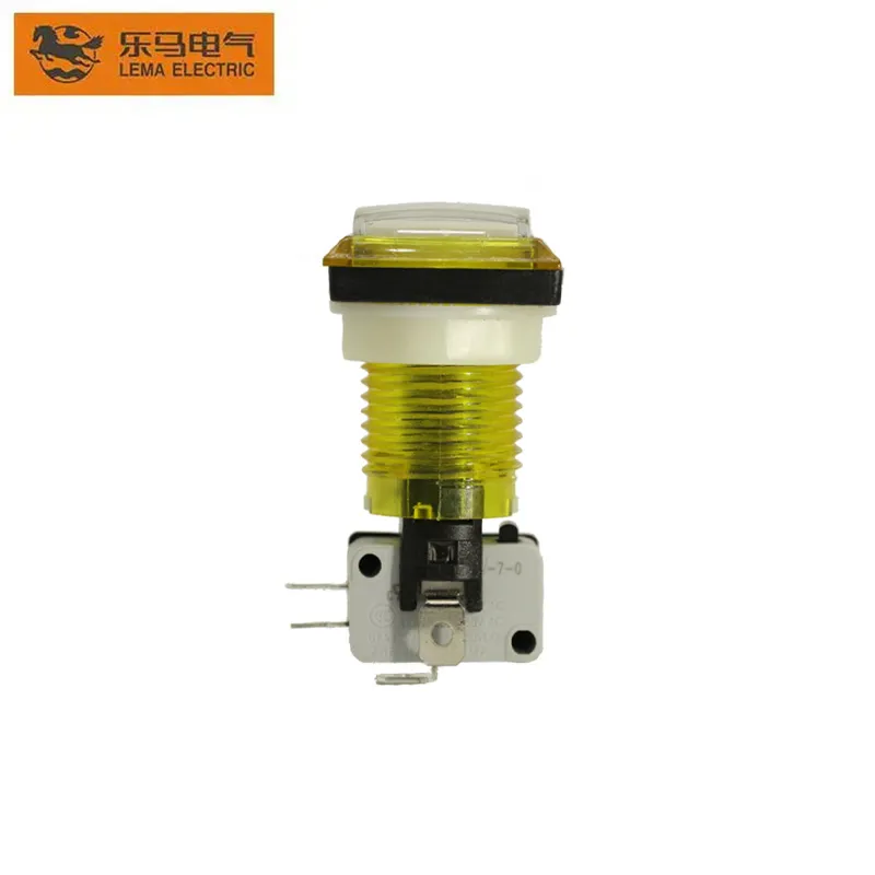
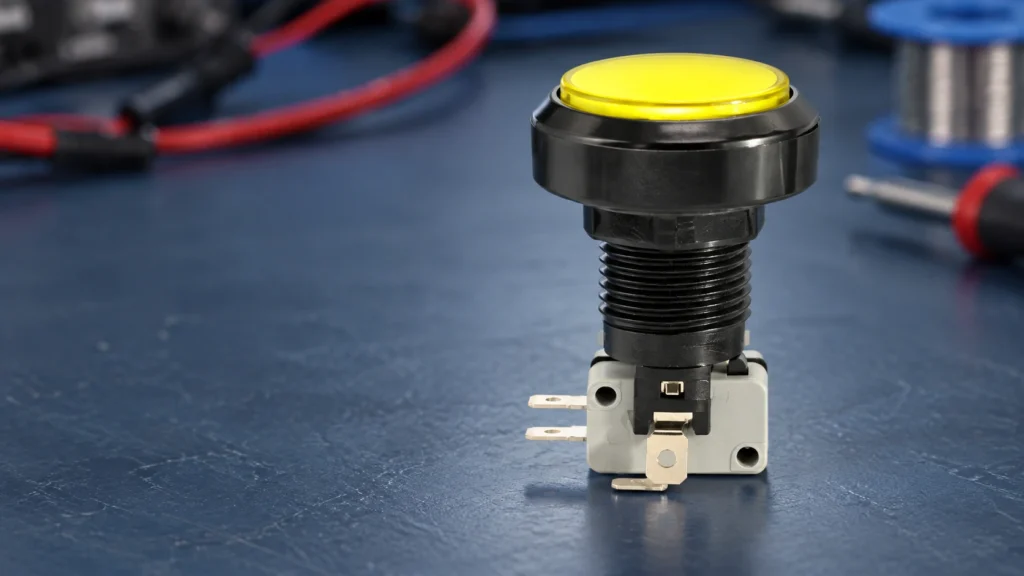
A push button switch symbol combines two separate ideas: the actuator that a person presses and the electrical contact state that changes. Read the contact in its normal, unactuated and de-energized condition unless the drawing states otherwise. A normally open contact is open at rest and closes when actuated; a normally closed contact is closed at rest and opens when actuated. An illuminated push button also has a lamp or LED circuit, which must be shown and wired separately from the contact circuit. This guide explains how engineers, panel builders and buyers should interpret NO, NC, changeover, maintained, momentary and illuminated push-button symbols. It does not replace the symbol legend, applicable drawing standard or terminal diagram for the exact product. Common push-button symbol meanings Drawing elementMeaning at normal stateChange when pressedTypical verification NO make contactCurrent path is openContact closesCOM–NO continuity appears NC break contactCurrent path is closedContact opensCOM–NC continuity disappears Changeover contactCOM is connected to NCCOM transfers to NOMeter both paths in both states Momentary actuatorReturns when releasedOperates only while force is appliedRelease test through full travel Maintained actuatorRemains in selected stateRequires another action to resetOperate and reset according to drawing Lamp or LEDIndependent indicator circuitIlluminates when its supply is presentCheck rated voltage and LED polarity Graphic details vary among IEC, ANSI and company-specific drawing systems. The project legend governs the drawing. The functional questions remain the same: what is the normal state, what mechanical action causes transfer, which terminals belong to each contact, and what returns the device to normal? LEMA PBS-001 product reference. A product photograph shows construction, while the schematic symbol and terminal drawing define electrical behavior. Start from the normal state “Normal” usually means the device...

Read More
Single-Pedal vs Dual-Pedal Foot Switch
Blog LEMA Electric

Single-Pedal vs Dual-Pedal Foot Switch

A single-pedal foot switch is usually the clearer choice when an operator needs one deliberate command. A dual-pedal foot switch is appropriate when two distinct commands must remain available at the same workstation, such as raise/lower or clamp/release. Pedal count alone does not make either design safer. The machine risk assessment, control logic, guarding, pedal spacing, operating force, cable arrangement and validation determine whether the selected control is suitable. For purchasing, define what each pedal must do in every machine state before choosing the enclosure. This guide compares single- and dual-pedal layouts for industrial and OEM equipment. It uses LEMA LF-series product shapes as real construction references, but it does not assign an unverified safety function, ingress rating or electrical rating to a photographed model. Always confirm the exact ordering code, drawing and test record. Single pedal versus dual pedal at a glance Decision pointSingle pedalDual pedalWhat to verify Number of commandsOne command or one hold-to-run functionTwo clearly separated commandsMachine operating narrative and I/O list Operator choiceLower selection burdenRequires reliable left/right or front/rear identificationPedal spacing, labels and usability trial Control contactsOne contact set or one control channelIndependent contacts or circuits may be requiredExact schematic and continuity test Cable and connectorUsually fewer conductorsMay need separate returns, commons or connector pinsHarness drawing and connector pinout Failure analysisOne actuator to diagnoseCross-wiring and command confusion must be consideredFMEA, commissioning and fault tests Best fitStart, jog, enable or one-direction requestTwo-direction or two-stage operator requestsApplication-specific risk assessment A dual pedal should not be selected merely because it leaves room for future functions. An unused pedal can still be pressed, misunderstood or wired incorrectly. If the equipment only needs one command, a single pedal normally makes the...

Read More
ON-ON-ON Toggle Switch: Circuit Logic and Wiring
Blog LEMA Electric

ON-ON-ON Toggle Switch: Circuit Logic and Wiring

An ON-ON-ON toggle switch is a three-position selector with an active contact combination in all three lever positions. In the common DPDT six-terminal version, the two poles do not necessarily transfer in the same way at the center position: one pole may connect toward one end while the other connects toward the opposite end. That staggered center logic is what makes series/split/parallel and other three-mode circuits possible. Never wire it from an ON-OFF-ON diagram; identify every continuity pair on the exact switch first. This guide explains ON-ON-ON toggle switch logic, terminal mapping, bench testing and OEM selection. LEMA product photos illustrate the physical DPDT toggle form and six-terminal layout. The referenced LT3230C listing is ON-OFF-ON, so its exterior photograph must not be treated as proof of ON-ON-ON internal contacts. ON-ON-ON is a contact sequence, not an appearance Three-position toggles can share the same lever, bushing and terminal footprint while having different internal sequences. ON-OFF-ON opens both poles in the center. ON-ON uses two maintained positions. Momentary functions are shown with parentheses, such as (ON)-OFF-(ON). ON-ON-ON maintains a defined connection in every position. The ordering code and contact table, not the number of detents or terminals, distinguish them. MarkingLever positionsCenter behaviorDo not assumeON-ONTwo maintainedNo center detentNot a three-mode selectorON-OFF-ONThree maintained or mixedBoth poles normally openCenter is not an active routeON-ON-ONThree maintainedStaggered or defined active contactsCenter pattern is not universal(ON)-OFF-(ON)Momentary endsOpen centerLever does not stay at the ends Some suppliers publish more than one ON-ON-ON center-contact pattern. A guitar-wiring source may call them Type I and Type II; industrial datasheets may use a contact truth table. Both descriptions mean the assembler must verify the exact variant. A familiar six-lug drawing from another...

Read More
IEC C20 Inlet vs C14 Inlet for Equipment Power
Blog LEMA Electric

IEC C20 Inlet vs C14 Inlet for Equipment Power

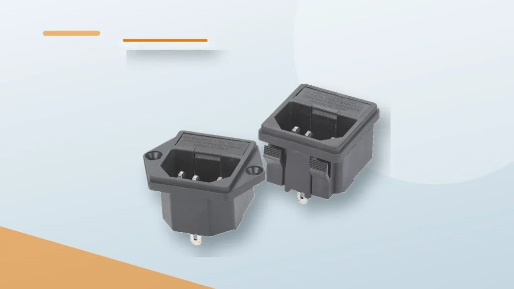
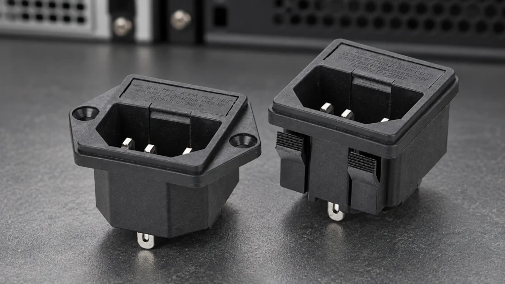
IEC C14 and C20 are grounded appliance inlets from the IEC 60320 family, but they are different interfaces and are not interchangeable. C14 mates with a C13 cord connector; C20 mates with a C19 connector. C20 is the larger choice used when the equipment input current exceeds what an approved C14 implementation can provide. The final rating is never selected by shape alone: check the exact inlet, cord set, fuse, wiring, terminal, ambient temperature, approvals and destination-market rules as one power-entry system. This C20 vs C14 inlet comparison is for OEM equipment design. LEMA’s current product-image library provides a C14-style IPZ inlet reference, so the photographs below deliberately do not claim to show a LEMA C20 product. Connector identities and mating pairs The equipment-side male appliance inlet is designated C14 or C20; the cord-side female connector is C13 or C19 respectively. The different outlines help prevent an unintended mating combination. IEC 60320-1 sets general appliance-coupler requirements, while IEC 60320-3 contains the standard sheets and gauges that define dimensional compatibility. The current IEC 60320-1 publication applies to appliance couplers integrated into equipment, and IEC 60320-3 covers the standard dimensions. Decision pointC14 inletC20 inletOEM actionMating cord connectorC13C19Specify both inlet and approved cord setPhysical interfaceSmaller standard-sheet geometryLarger, differently keyed geometryUse the exact manufacturer cutout drawingCurrent classCommon lower-current equipment inputHigher-current IEC 60320 optionUse the marked/approved rating for market and temperatureTypical system impactSmaller cutout and cord ecosystemLarger inlet, cord and conductor requirementsReview fuse, terminals, wire gauge and thermal rise togetherDirect substitutionNo; connector, cutout and cord set differRequalify the complete power-entry design A common shorthand describes C14 as a 10 A international interface and C20 as a 16 A international interface, with different approved values possible...

Read More
5-Pin Push Button Switch Wiring With LED
Blog LEMA Electric

5-Pin Push Button Switch Wiring With LED

A typical 5-pin illuminated push button contains two electrically separate parts: a three-terminal changeover switch marked COM, NO and NC, plus two lamp terminals. Wire and test those parts independently. With power isolated, identify COM–NO and COM–NC by continuity; then confirm the lamp’s rated voltage and, for an LED, its polarity. Do not copy a color code or terminal position from another brand. The exact LEMA drawing and markings for the selected PBS variant must control the final connection. This guide explains the logic behind a 5-pin push button switch wiring diagram without presenting one terminal layout as universal. It covers momentary control, constant and switched illumination, PLC inputs, commissioning and the information an OEM should place on its drawing. Separate the contact circuit from the light circuit The contact section is normally an SPDT changeover contact. COM is the moving common. At rest, COM is connected to NC and isolated from NO. When the mechanism is fully actuated, COM connects to NO and leaves NC. The two remaining terminals supply the lamp. Their voltage is not automatically the same as the load circuit, and an LED normally requires the specified polarity. Some illuminated devices include current limiting for a declared supply; others require an external circuit. Treat the product datasheet as the authority. Terminal functionState at restState while actuatedVerificationCOMCommon path to NCCommon path to NOContinuity meter with power isolatedNOOpen to COMClosed to COMRecord resistance in both positionsNCClosed to COMOpen to COMRecord resistance in both positionsLamp + / anodeDepends on the desired illumination behaviorDatasheet marking and controlled low-voltage testLamp − / cathodeReturns to the approved lamp supplyDatasheet marking; do not infer from wire color The table describes a common arrangement,...

Read More
Safety Foot Switch With Guard: Selection and Placement
Blog LEMA Electric

Safety Foot Switch With Guard: Selection and Placement

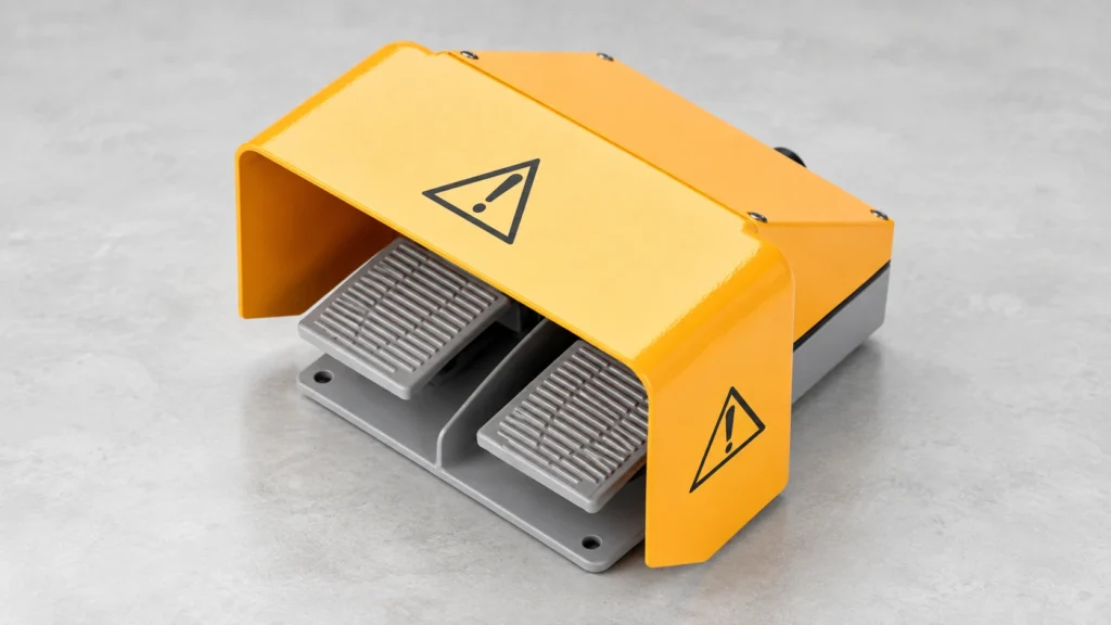
A safety foot switch is not defined by a yellow hood or a warning symbol. A guarded foot control can reduce unintended pedal activation, but safe machine operation depends on the whole system: the machine's hazards, point-of-operation safeguarding, control logic, fault response, mounting position, operator access, and validation. For a buyer comparing guarded pedals, first specify what accidental actuation the cover must resist and what intentional foot movement it must allow. Then confirm the exact pedal's mechanical and electrical details and have the machine safety function assessed by a qualified person. This guide uses LEMA's real guarded LF-series foot-switch construction as a selection example without claiming an unverified safety certification. Original LEMA LF-62 product-and-dimension image. The visible yellow hood covers two gray pedals; it is a physical guard feature, not evidence of a certified safety function. What a guarded foot switch does A foot switch lets an operator initiate or control a machine function while keeping the hands free. A protective hood or shroud can make it harder for a falling object, another person's step, or an unintended sideways movement to press the pedal. The shape, opening, side walls, and location matter: a cover that looks substantial in a catalog may still allow an object to enter from the front or a shoe to reach the pedal unintentionally. The real risk must be tested at the intended installation. For mechanical power presses, the US OSHA foot-control guidance warns that foot controls leave the operator's hands free and do not themselves separate hands from the point of operation. It also identifies inadvertent pedal activation as a hazard and calls for guarding and other safeguards in relevant press applications. That is a...

Read More
6-Pin Toggle Switch Wiring: Verify a DPDT Terminal Layout
Blog LEMA Electric

6-Pin Toggle Switch Wiring: Verify a DPDT Terminal Layout

6-pin toggle switch wiring usually refers to a double-pole, double-throw (DPDT) switch: two independent changeover contact sets operated by one handle. Each pole has a common and two possible throws, giving six external terminals. Do not wire a switch from the pin count or a generic photograph alone. Identify the exact model and its ON-ON, ON-OFF-ON, momentary, or other action; then test the de-energized terminals for continuity in every handle position. Only after that map should a qualified person connect a circuit that fits the switch's ratings and the equipment's protection design. This guide focuses on terminal identification and verification, not an untested universal pinout. Original LEMA LT2220C product photo. Six flat terminals can be inspected from this angle; their functional mapping must still be verified from the exact drawing and continuity test. What six terminals mean—and what they do not A DPDT toggle is functionally two SPDT changeover contacts moved together. Pole A and pole B are electrically separate until an external circuit connects them. Each pole has a common terminal that connects to one throw in one position and the other throw in the opposite position. The switch can route two independent signals, or be arranged for another appropriate application after the circuit designer verifies ratings and fault behavior. Six terminals do not reveal which physical lug is common on a particular model, and they do not reveal whether the center position is OFF. The City Tech electronics lab manual treats a DPDT as a two-state input and explicitly tells students to check continuity because a real switch can differ from the illustrated pattern. A South African Department of Basic Education learner book explains a DPDT as two...

Read More
Micro Switch Electrical Life vs Mechanical Life: What the Ratings Mean
Blog LEMA Electric

Micro Switch Electrical Life vs Mechanical Life: What the Ratings Mean

Micro switch electrical life vs mechanical life compares two different endurance tests. Mechanical life counts operations at a stated speed and travel without an energized contact load. Electrical life counts operations while the contacts switch a specified voltage, current, and load type. The figures are not interchangeable, and neither is a calendar-life promise for a finished machine. A buyer should ask for the exact model's test conditions, then compare them with the machine's real actuation rate, overtravel, inrush, duty cycle, environment, and acceptable failure risk. This guide explains how to read those figures without inventing a life rating for a LEMA part that has not been tested in your assembly. Original LEMA KW12-series product photo. The plunger and lever affect how the switch is operated; the image itself does not establish a cycle-life rating. What is mechanical life? Mechanical life, also called mechanical durability, describes the number of full switch operations achieved under a stated mechanical test, normally with the contact circuit not energized. An operation means the actuator is moved through its specified operating and release sequence, not merely touched. The test must define operation frequency, stroke or overtravel, operating speed, mounting, and the criterion used to call the switch failed. A mechanism can lose its snap action, spring force, return behavior, or dimensional stability even if no electrical load is switched. The IEC 61020-1 publication description identifies electromechanical switches as devices that change an electrical connection through mechanical contact motion and says the generic specification addresses terminology and test methods. That is a useful framework, not evidence that any particular KW12 model meets a specific endurance value. For the mechanical side of a purchased model, request the manufacturer's...

Read More