DPST Toggle Switch Wiring for Two-Circuit Isolation
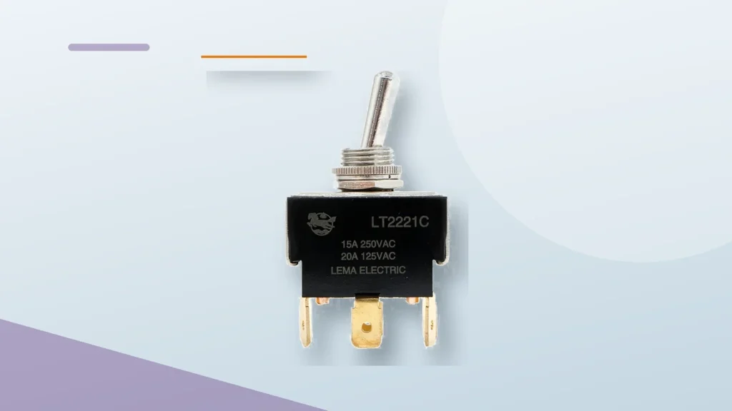
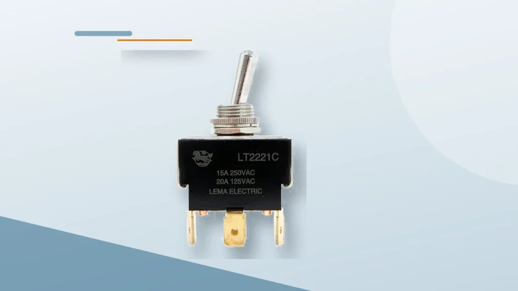
Dpst toggle switch wiring should be selected by matching the electrical function, mechanical interface, environment, and verification plan—not by copying a generic diagram or choosing from appearance alone. A DPST toggle contains two poles that change state together for simple two-circuit on/off isolation. It is not the same as DPDT, which provides two throws per pole. Terminal position varies by model, so continuity must be verified against the manufacturer's diagram before conductors are connected. This guide gives engineers and OEM buyers a practical way to define the requirement, compare samples, and avoid a part that works on the bench but fails after installation. Application-focused view using the matching LEMA product. What the term means in this application A DPST toggle contains two poles that change state together for simple two-circuit on/off isolation. It is not the same as DPDT, which provides two throws per pole. Terminal position varies by model, so continuity must be verified against the manufacturer's diagram before conductors are connected. The first job is to separate the switch's name from its required behavior. Product names are often shortened for search or purchasing, while an engineering drawing defines the contact state, terminal numbering, operating point, allowable travel, mounting reference, and ratings. If those details are missing, two parts with similar names may behave differently. Write the control requirement as a short sequence: the condition before actuation, the physical action that causes actuation, the electrical state after actuation, and the condition that resets it. This sequence prevents confusion between mechanical action and contact logic. It also gives the controls engineer, mechanical designer, buyer, and supplier one shared description to review. Do not treat a catalog current rating as a...
Read More