LEMA NACHRICHTENZENTRUM

Nachrichten & Blog

Nachrichtenzentrum

Schaltschalter-Motorsteuerung: Wenn ein Relais erforderlich ist
Blog LEMA Electric

Schaltschalter-Motorsteuerung: Wenn ein Relais erforderlich ist

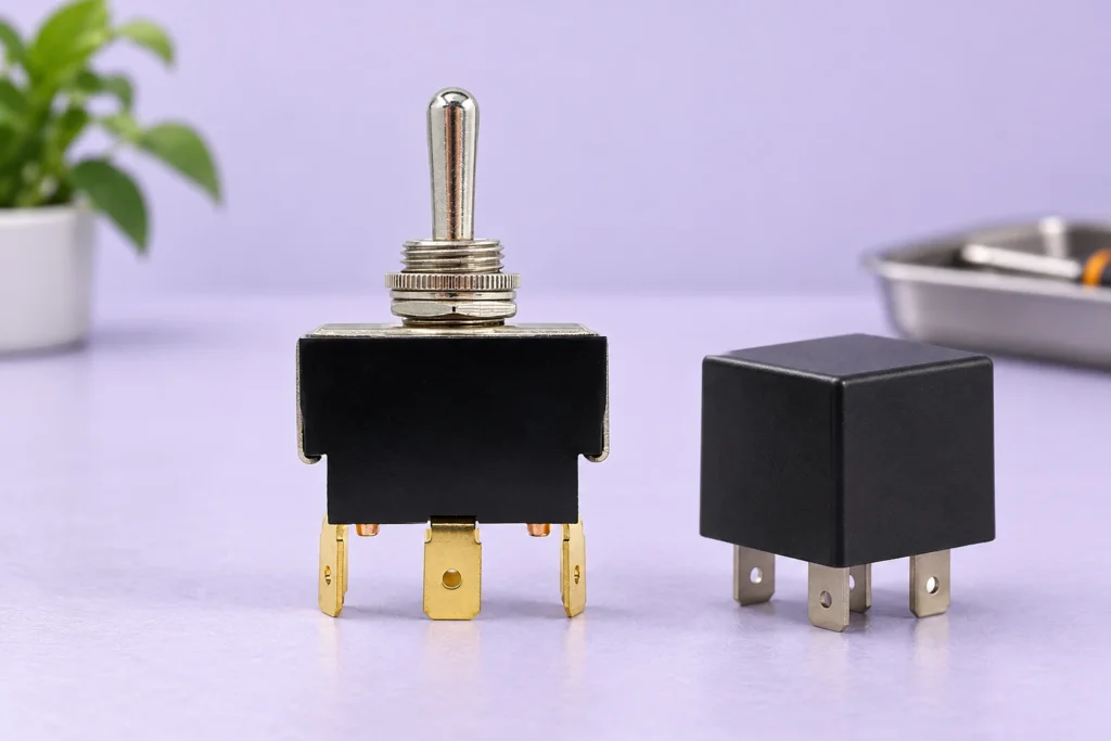
Ein Kippschalter zur Motorsteuerung darf den Motor nur dann direkt schalten, wenn für genau diesen Schalter dokumentiert ist, dass er für die Motorspannung, die Stromart, die Anlaufbelastung und die Schaltbedingungen geeignet ist. Andernfalls kann ein geeigneter Relais-, Schütz- oder elektronischer Motorregler die Leistung schalten, während der Kippschalter lediglich einen Steuerbefehl liefert. Das Hinzufügen eines Relais macht den Stromkreis nicht automatisch geeignet: Spule, Kontakte, Schutzmaßnahmen und Verhalten beim Wiederanlauf müssen weiterhin überprüft werden. Dieser Leitfaden hilft OEMs dabei, einen rastenden Schaltbefehl über einen Kippschalter vom Leistungspfad des Motors zu unterscheiden und eine vollständige Konstruktionsanfrage vorzubereiten. Zunächst feststellen, was der Kippschalter tatsächlich schaltet Verfolgen Sie den Stromkreis vom Bediener bis zur Last. Bei einer direkten Schaltung fließt der Motorstrom durch die Schaltkontakte des Kippschalters. Bei einer indirekten Schaltung kann der Kippschalter eine Relaisspule erregen oder einen Eingang an einem Motorregler umschalten. Diese Schnittstellen stellen unterschiedliche elektrische Anforderungen, selbst wenn derselbe Frontplattenhebel verwendet wird. Dokumentieren Sie die Versorgungsspannung, AC oder DC, den Motortyp und den vorgesehenen Betrieb. Anlaufen, Anhalten, Tippbetrieb und Umkehren der Drehrichtung sind unterschiedliche Belastungsarten. Geben Sie die erwartete Schalthäufigkeit und die Anlaufdaten des Motorherstellers an. Der Betriebsstrom allein beschreibt nicht die Kontaktbelastung beim Anlaufen eines Motors oder beim Unterbrechen eines induktiven Stromkreises. Wenn die Belastungsbedingungen unbekannt sind, beschaffen Sie vor der Bauteilauswahl gemessene oder vom Hersteller bestätigte Daten. Interpretieren Sie eine AC-Nennlast für ohmsche Verbraucher nicht als DC-Motornennlast. Ebenso wenig belegt ein auffälliger Stromwert auf einem Produktfoto eine Gebrauchskategorie oder eine zulässige Motorgröße. Die Abbildungen der LEMA-LT-Serie kennzeichnen eine Produktfamilie und zeigen deren sichtbare Konstruktion. Die Eignung für einen bestimmten Motorkreis muss sich aus der elektrischen Dokumentation der exakt bestellten Variante und der Geräteauslegung ergeben. Metallhebel der LT-Serie, Gewindebuchse und drei Messinganschlüsse auf einer ...

Mehr lesen
Abmessungen des Ausschneidebereichs des Drucktaster-Bedienfelds: Zeichnung und Passformkontrollen
Blog LEMA Electric

Abmessungen des Ausschneidebereichs des Drucktaster-Bedienfelds: Zeichnung und Passformkontrollen

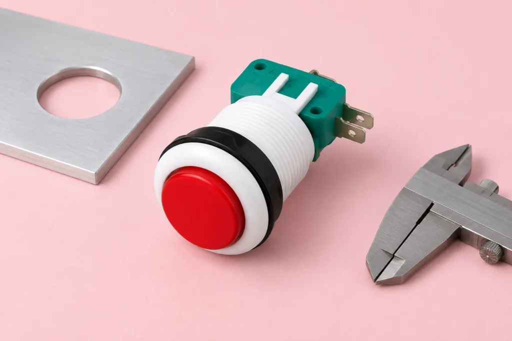
An industrial push button panel cutout size comes from the approved mounting drawing for the exact operator, not from its cap diameter or a generic product-family name. Check the opening shape and tolerance, finished panel thickness, anti-rotation features, retaining hardware and rear clearance together before cutting a production panel. A button that enters the hole can still be poorly retained or impossible to wire. This guide explains how an OEM turns the drawing into a fabrication and sample-inspection record without transferring another manufacturer's dimensions to a LEMA PBS product. Separate the actuator, bezel, mounting body and hole A front-view photograph contains several circles, and only one may describe the mounting interface. The visible actuator is the surface an operator presses. The bezel surrounds it. A threaded body or mounting collar passes through the panel. The drawing specifies the opening that accepts that body, sometimes with a flat, keyway or secondary notch. Measuring the largest visible circle therefore does not identify the required hole. Keep those dimensions in separate fields. Label the front clearance envelope, mounting opening and rear envelope explicitly on your panel layout. The bezel can overlap the opening while the contact block extends sideways behind it. Adjacent operators may clear each other on the front yet interfere through their terminals, clips or cable bends. A complete mounting review follows the whole assembly through the panel. LEMA's PBS original includes front and side views with several different dimensions. Treat those views as product-reference information and request the current drawing for the ordered variant. This article intentionally gives no universal PBS hole diameter: a depicted head measurement, a body dimension and a manufacturing cutout are different quantities. Copying one number...

Mehr lesen
Schalter mit Drucktaste: Strombelastung: Passen Sie den Kontakt an die Last an
Blog LEMA Electric

Schalter mit Drucktaste: Strombelastung: Passen Sie den Kontakt an die Last an

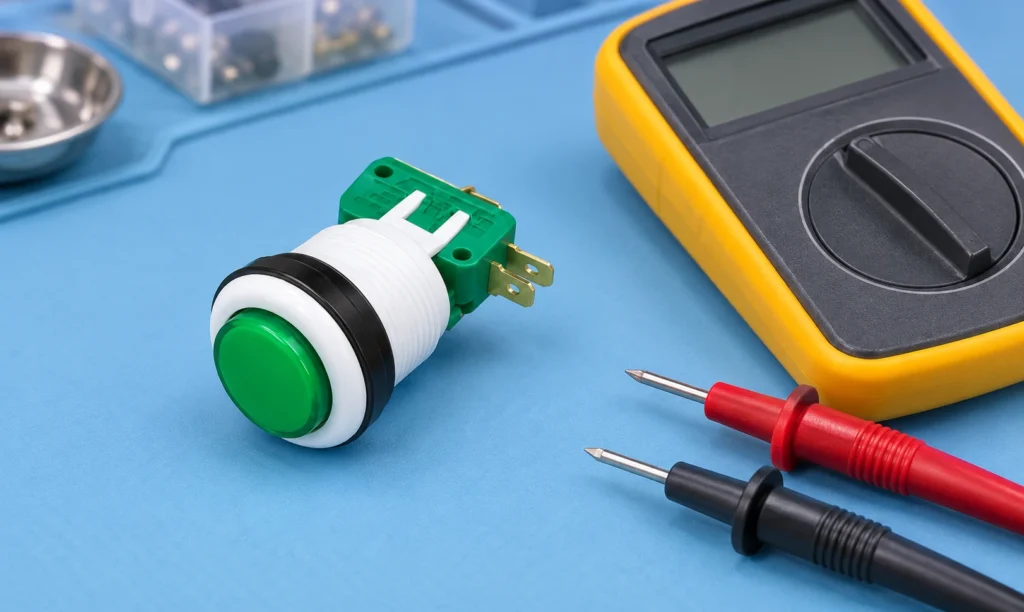
A push button switch current rating applies to a defined electrical duty, not to every load drawing fewer amperes. Match the exact contact's voltage, AC or DC conditions, load type, making and breaking duty, operating frequency and installation conditions. A resistive rating does not automatically approve a motor, solenoid or electronic power supply. A high-current contact is also not necessarily the best choice for a low-level controller input. This guide explains how to collect and compare those requirements before purchasing a push button or approving a component substitution. The focus is contact-load compatibility for equipment controls. Mechanical operation, button colour and terminal count remain separate selection questions. The pictured LEMA PBS-001 button is a physical product reference; no current, voltage or protective-function rating is inferred from its appearance. Electrical measurements and circuit modifications belong to qualified personnel using an approved equipment procedure. Identify what the button actually switches Begin at the schematic. A button may connect directly to a load, operate a relay coil, signal a controller input or perform another defined function. Those arrangements can place very different demands on the contact. Record the electrical component immediately downstream of the button rather than assuming that the machine's motor power flows through the operator control. Trace the actual contact circuit independently of any lamp circuit. An illuminated button can have separate terminals and supply conditions for its indicator. A lamp specification does not describe the switching contact. Equally, the presence of several terminals does not establish a particular internal diagram. Use the drawing for the exact order code and confirm its contact arrangement. The industrial push button selection guide provides the broader mechanical and functional context. This article concentrates on...

Mehr lesen
IEC-Eingangstemperaturen: Pinlimits, Umgebungstemperatur und Montagewärme
Blog LEMA Electric

IEC-Eingangstemperaturen: Pinlimits, Umgebungstemperatur und Montagewärme

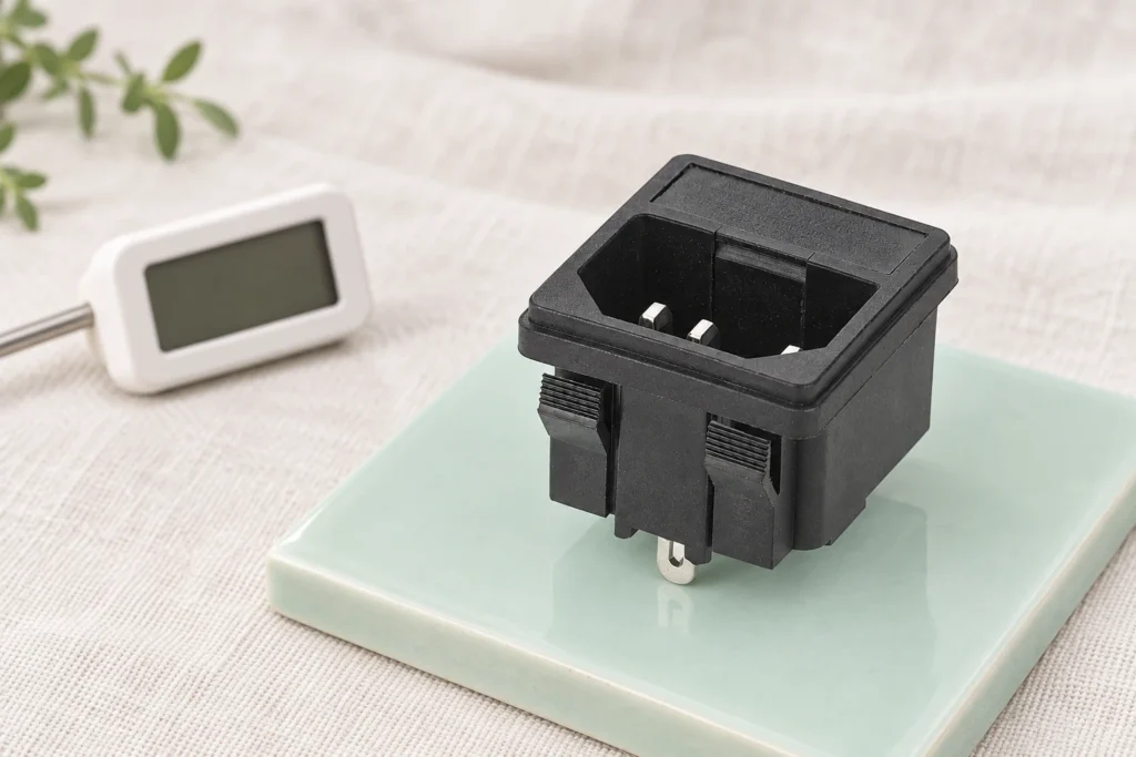
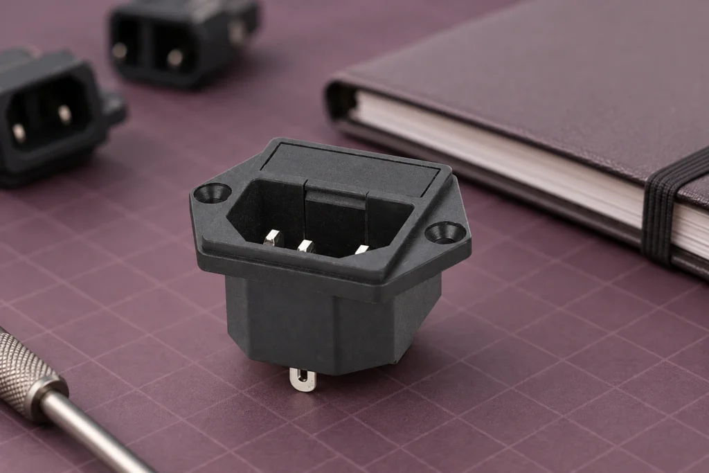
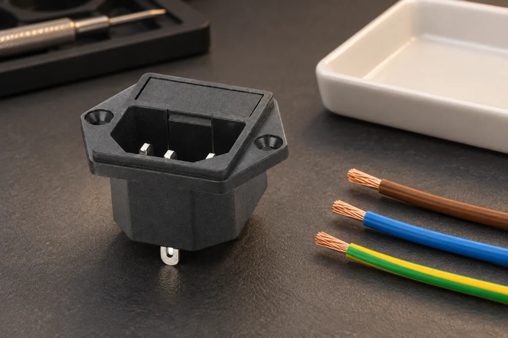
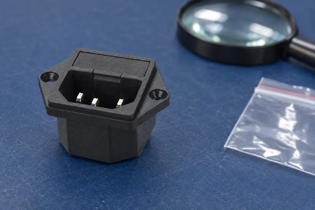
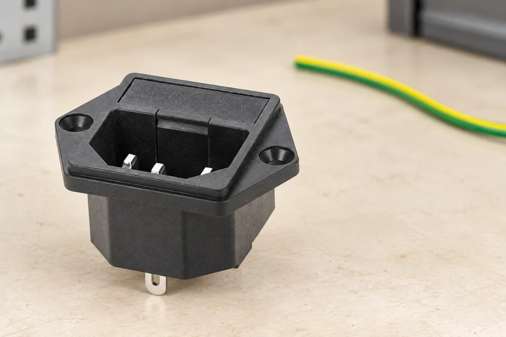
An IEC inlet temperature rating is meaningful only when you know what temperature it describes. Maximum pin temperature, permitted ambient temperature and temperature rise are different quantities. A connector family associated with a higher pin temperature does not automatically approve an inlet for a hotter enclosure or a larger current. Identify the exact inlet, its mating connector and the applicable product documents, then review the thermal conditions of the complete equipment. This guide separates those checks so that buyers do not treat a housing photograph, a material description or a familiar connector name as thermal approval. The intended readers are equipment designers, purchasing teams and qualified maintenance personnel. Illustrations use a real LEMA IPZ snap-in inlet as a visual reference. They do not establish its connector classification, temperature limit or certification. Electrical and thermal testing must follow a procedure defined for the actual equipment; this article does not provide universal acceptance limits. Separate three temperatures before comparing products Pin temperature concerns a specified part of the connection. Ambient temperature concerns the surrounding air under defined conditions. Temperature rise is the measured increase above the reference ambient during a defined test. A document may discuss all three, but a number from one category should never replace a missing number in another. Record the measurement location and condition with every temperature value. Consider a hypothetical component described by a maximum pin temperature. That statement alone does not tell you its permitted local ambient, how much rise it develops at a particular current or whether nearby equipment can expose its plastic body to additional heat. Similarly, a housing material's laboratory property is not a rating for the assembled inlet. Ask for the finished...

Mehr lesen
10A vs. 15A IEC-Eingang: Vergleich der Zulassung und des kompletten Stromverlaufs
Blog LEMA Electric

10A vs. 15A IEC-Eingang: Vergleich der Zulassung und des kompletten Stromverlaufs

A 10A vs 15A IEC inlet comparison must start with the exact component approval, its voltage and its intended market. Two numbers on a catalogue page do not necessarily describe two physically different products, and a higher number does not automatically increase the permissible load of the complete equipment. Identify which rating applies to the purchased variant and the matching cord set. Then check the internal wiring, terminals, protective devices and equipment requirements. This guide explains that decision process without assigning a regional current rating or certification to an inlet based on its photograph. It is intended for equipment designers, purchasing teams and competent service personnel. The illustrated LEMA inlet provides a product reference for discussing mounting and identity; it is not an approval certificate. Any live measurements or equipment modifications require qualified personnel following an approved procedure. This article concerns detachable equipment power interfaces rather than replacing domestic wall outlets. Read the rating together with its approval context A useful rating record includes more than amperes. Record the manufacturer, exact order code, voltage, applicable approval scheme, temperature conditions, terminal version and any installation conditions. When a supplier lists both 10A and 15A, ask whether the values come from different certification evaluations or refer to different variants. Do not combine a current from one line with a voltage from another to create a rating that was never declared. The IEC 60320-1 catalogue entry identifies the standard family for appliance coupler general requirements. That entry establishes the subject of the standard, not the approval of a particular purchased inlet. The related standard sheets and the product's certification documents provide the details needed for a specific comparison. Keep the edition used in...

Mehr lesen
So testen Sie einen Drucktaster mit einem Multimeter
Blog LEMA Electric

So testen Sie einen Drucktaster mit einem Multimeter

To test a push button switch with a multimeter, first establish a safe de-energized condition and isolate the contacts from other circuit paths. Identify the intended contact pair from the exact switch drawing, check the meter and leads, then record the reading with the button released, pressed and released again. A normally open pair should change from open to closed when operated; a normally closed pair should do the reverse, according to its documented mechanism. This procedure checks contact-state behavior. It does not prove load capacity, endurance, safety certification or the complete machine response. This guide is a bench measurement and recordkeeping workflow for ordinary discrete push button contacts. Electronic touch buttons, illuminated assemblies and protective devices may require different procedures. The product illustrations show a LEMA PBS example for identification; they are not universal pin-number diagrams or instructions for live testing. Define the question before selecting a meter function Decide whether you need to identify a contact pair, confirm released and operated states, investigate an unstable reading or compare a sample against an approved requirement. These are related questions but have different conclusions. A continuity test can reveal an open connection or a state change. It cannot establish the correct electrical duty for a motor, determine an endurance rating or approve a protective control. For a machine that fails to respond, use the separate push button troubleshooting guide to distinguish actuator, wiring and controller faults. This article focuses on repeatable isolated measurements. Do not remove a working button from its circuit merely because the controller’s response is unfamiliar; start with the equipment schematic and documented command sequence. Have the exact order code, terminal drawing and action description available. Identify...

Mehr lesen
Ersatz eines industriellen Fußschalters: Passende Schaltfunktion, Kabel und Schnittstelle
Blog LEMA Electric

Ersatz eines industriellen Fußschalters: Passende Schaltfunktion, Kabel und Schnittstelle

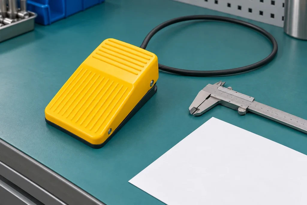
An industrial foot switch replacement must preserve the original command behavior, electrical interface and installation requirements. A similar pedal shape or matching plug is not enough. Record the original part and machine response, compare the candidate against the approved documentation, and validate the finished assembly before return to service. This guide covers ordinary industrial command pedals and their replacement evidence. It does not approve substitutions in emergency-stop, enabling, guarding or other protective functions, and it does not address guitar effects, sewing-machine speed controllers or household lamp foot switches. For equipment builders and maintenance buyers, the practical question is whether a proposed substitute reproduces the complete approved function. The pedal, cable, connector and receiving input all matter. Keep that comparison separate from a catalogue search so availability does not silently override the machine requirements. Capture the original configuration before removal Record the full pedal order code, visible markings, cable identification, connector details and machine drawing revision. Photograph the as-installed location and routing before moving anything. Note whether the unit is loose on the floor, fixed to a support or part of a guarded station. Include any secondary command, indicator or mechanical feature that participates in normal operation. Write down what the machine does when the operator presses and releases the pedal. Distinguish a momentary command from a maintained state and from a controller that retains a command after a short press. Observe the documented sequence rather than conducting an unsafe experiment. If the machine is already faulty, use the approved description and records; the failed behavior is not the reference that the replacement should reproduce. Consult the industrial electric foot switch selection guide when reconstructing the initial requirements. A replacement review...

Mehr lesen
Geräte-Steckdose – Polarität: Überprüfen Sie den kompletten Stromversorgungsweg
Blog LEMA Electric

Geräte-Steckdose – Polarität: Überprüfen Sie den kompletten Stromversorgungsweg

Equipment power socket polarity means the intended line, neutral and protective conductor paths remain correctly identified through the cord, connector, inlet and internal assembly. Alternating current does not make those conductor roles interchangeable. Verify the exact connector drawing and equipment circuit before interpreting a photograph or performing a test. A connector that fits, a machine that powers on, or a three-light socket tester alone does not prove the complete assembly is correct. This guide focuses on equipment inlet identity and verification records, rather than household receptacle repair or a universal pin-position diagram. The intended readers are equipment builders, procurement teams and competent maintenance personnel. Electrical inspection and testing must follow the actual equipment requirements and workplace procedures. The illustrated product is a visual reference, not a verified wiring assignment. Do not infer a terminal function from the location shown in an illustration. Separate polarity from protective earthing In a supply system that distinguishes line and neutral, polarity concerns the connection of those conductors to their intended points. Protective earth, when required by the equipment design, serves a different purpose. It is part of a protective path rather than a substitute return conductor. Do not connect neutral to an enclosure inside the equipment simply because both conductors may have an earth-related relationship elsewhere in a particular supply system. The design determines how the inlet, protective devices and internal circuit relate. A correct inlet termination does not establish that the complete cord assembly or upstream installation is correct. Equally, a correct supply socket cannot compensate for a miswired internal harness. Review these as connected parts of one path, with each boundary clearly identified in the verification record. For the protective-path design itself,...

Mehr lesen
Fehlerarten von Steckdosen: Lose Kontakte, Überhitzung und Lichtbogenbildung
Blog LEMA Electric

Fehlerarten von Steckdosen: Lose Kontakte, Überhitzung und Lichtbogenbildung

Power socket failure modes in equipment include a damaged mating interface, loose or unsuitable terminations, inadequate mechanical retention, contamination and deterioration associated with heat or electrical discharge. A darkened housing is evidence to investigate, not a diagnosis by itself. Remove affected equipment from use under its approved isolation procedure and preserve the inlet, mating connector and connection records before replacing parts. This guide concerns panel-mounted equipment power inlets such as the LEMA IPZ family, not household receptacle repair. Qualified personnel must establish the complete fault and validate the correction; reconnecting a damaged inlet to see whether it works is not an acceptable investigation method. Define which part of the power interface failed An equipment power interface includes the supply cord, mating connector, inlet contacts, housing, mounting and internal terminations. Some arrangements also contain a fuse drawer, switch or other component. The observed symptom may arise at any of those boundaries. Record the exact configuration and component order codes before calling every failure a socket fault. A replacement inlet cannot correct a defective cord connector or an incorrectly assembled internal termination. Separate loss of power, intermittent operation and visible damage as observations. A device that stops operating may have an open connection, a protective device operation or a fault elsewhere in the equipment. A connector that moves may reflect panel retention or a mismatched mating interface. Use the original machine documentation and approved diagnostic process to establish which boundary is involved rather than replacing the most accessible part first. The LEMA IPZ power inlet product page supplies the real reference shown in the illustrations. Its picture does not prove the operating history or cause of damage in a separate assembly. Request...

Mehr lesen
Metall- vs. Kunststoffgehäuse für Endschalter: Entscheidungsgrundlagen
Blog LEMA Electric

Metall- vs. Kunststoffgehäuse für Endschalter: Entscheidungsgrundlagen

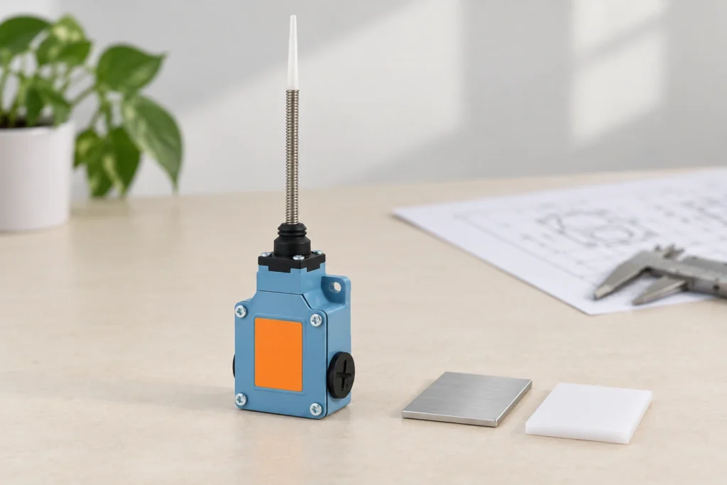
Choosing a metal vs plastic limit switch requires comparing the complete switch against its installation, not declaring one material universally superior. Housing material affects the engineering questions you ask about mechanical loading, conductivity, chemical exposure and assembly. It does not by itself prove an ingress rating, a temperature limit, a safety function or a longer service life. Start with the exact material and model, then request evidence for the conditions your machine creates. This guide compares enclosure-selection decisions for mechanical position switches. The illustrations show a real LEMA metal-body product reference; they do not depict or claim a verified plastic-body equivalent. Compare complete products with the same job A housing is only one part of a limit switch. The actuator transfers target movement, the contact assembly supplies the required electrical state, and the entries and cover form part of the installed enclosure. Two products with different housings may also differ in contact duty, mounting dimensions or actuator travel. A comparison that attributes every difference to metal or plastic can lead to an incompatible substitution. Define the position-detection job first: target approach, movement, repeatability requirement, electrical interface and installation environment. Then compare candidate models against those requirements. Keep the same acceptance criteria for both candidates. If one product has documented evidence and the other has only a general description, record the evidence gap rather than estimating its performance from appearance or price. RealPars' limit switch anatomy and operation lesson helps separate the actuator, enclosure and contact mechanism. The LEMA limit switch application guide provides the broader position-detection context. Use those principles to set up a comparison, then rely on order-code-specific drawings and test information for actual product approval. Name the metal...

Mehr lesen
AC Power Socket Grounding and Protective Earth for Equipment
Blog LEMA Electric

AC Power Socket Grounding and Protective Earth for Equipment

AC power socket grounding is the provision of an approved protective connection from the equipment's required exposed conductive parts through its power interface to the supply's protective system. At an equipment inlet, a third contact is only one part of that path. The mating cord, internal connection, enclosure bonding and installation must also be correct. Protective earth must not be confused with neutral or an electronic signal reference. This guide focuses on OEM equipment interfaces, not instructions for household wiring. Qualified designers and technicians must use the applicable equipment standard, installation requirements and manufacturer documentation when specifying or checking the complete protective arrangement. Identify the equipment protection concept first Determine whether the equipment uses protective earthing, double or reinforced insulation, or another approved protection concept. A plastic outer cover alone does not establish double insulation. A metal enclosure alone does not define the complete earthing arrangement. Obtain the equipment's approved documentation and markings before selecting its inlet or cord assembly. A component chosen only from its apparent contact count can conflict with the protection system already used by the equipment. For equipment that requires protective earth, document the complete path rather than a single green-and-yellow wire. Identify the supply interface, cord protective conductor, inlet contact, internal termination and required bonding points. Record removable covers or assemblies that require a defined connection. Do not rely on paint-covered mechanical fasteners or incidental touching between parts unless the approved design provides and verifies that function. The LEMA IPZ equipment power inlet family is the product reference used here. Its photographs show physical configurations, not proof of a particular assembled machine's safety. Request the selected order-code drawing, terminal identification and applicable component information. A...

Mehr lesen
Problembehandlung bei Limit-Schaltern: Kein Signal, Geräusche und Fehlposition
Blog LEMA Electric

Problembehandlung bei Limit-Schaltern: Kein Signal, Geräusche und Fehlposition

Limit switch troubleshooting should begin by locating where the expected position signal disappears: the machine target, actuator, contacts, cable or receiving controller. Secure the machine before inspection and compare the expected released and operated states with the approved drawing. Replacing the switch before making that comparison can hide a mounting or input fault. This guide concerns mechanical position switches on equipment. It does not cover furnace temperature-limit switches, whose protection function and diagnostic process are different. Never bypass a protective device to keep production running; unresolved safety-related faults require the machine's approved service and validation procedure. Preserve the fault before disturbing the installation Record the machine position, operating mode and symptom before loosening a bracket or disconnecting a cable. Note whether the missing signal occurs on every cycle, only at one travel direction or after a period of operation. Photograph the target-to-actuator relationship and any movement marks on the mounting surface. Keep controller messages and input observations with their timestamps so a later adjustment cannot erase the original evidence. Distinguish the process symptom from the electrical symptom. A carriage failing to stop is not, by itself, proof of a failed contact. The switch may not have been reached, its signal may not have reached the controller, or the control system may have recognised it without producing the expected response. Record what was observed at each boundary. The limit switch application guide explains the position-detection role; that role must be identified in the particular machine. Before hands-on work, follow the equipment's isolation process, including stored energy and motion hazards. OSHA hazardous-energy control requirements provide a United States workplace reference. A stopped drive or an off command is not necessarily an isolated...

Mehr lesen