LEMA NEWS CENTER

News & Blog

News Center

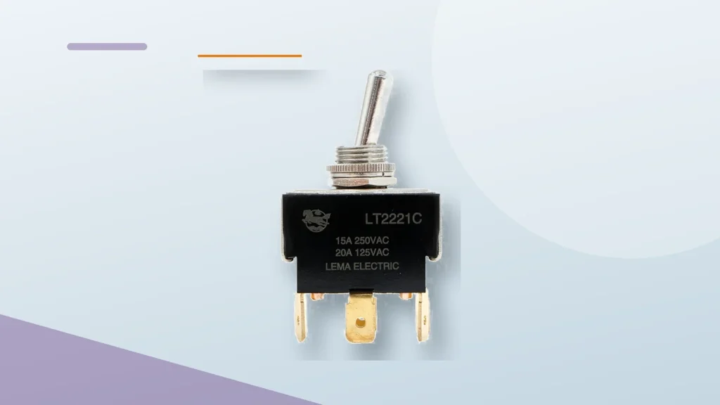
Identifying SPDT Toggle Switch Terminals for OEM Wiring
Blog LEMA Electric

Identifizierung der Anschlüsse eines einpoligen Umschalters (SPDT) für die OEM-Verkabelung

SPDT wiring fails when teams guess terminals from a lever photo. Lock the common and each throw on the schematic first, then assign harness pins. A clean panel still misbehaves when C and throw labels drift between drawing revisions. Important: Treat SPDT terminal identity as a drawing-controlled field, not a shop-floor nickname. Confirm contact paths against selected-model documentation before harness release. Source note: IEC 61058-1 publication scope and selected-model documentation. - FAQs ContentsPart 1. Which terminals define an SPDT toggle on the drawing?Part 2. How should common and throw pins be labeled in the harness?Part 3. When does SPDT wiring differ from simple ON-OFF slang?Part 4. Which load and panel notes still belong beside the pin map?Part 5. How do OEMs prevent terminal swaps during service?Part 6. How should SPDT wiring be validated before release?Part 7. How can LEMA support an SPDT wiring inquiry?Part 1. Which terminals define an SPDT toggle on the drawing? Start from the contact diagram: one common (C / COM) and two throws that the lever selects. Record which throw is ON in each maintained position and whether a center-off exists. Decision fieldInput to documentSend with quote Terminal mapC / throw labels on the drawingYes — labeled schematic Circuit formMaintained states the SPDT must expressYes — printed form Load pathWhich throw carries which loadYes — duty summary Panel fitCutout, thickness, clearanceYes — mounting envelope Browse the LEMA Toggle Switch product line only after the pin map exists. Part 2. How should common and throw pins be labeled in the harness? Harness labels should mirror the drawing characters exactly. If manufacturing uses color codes, keep a cross-reference table in the same package so service teams do not...

Mehr lesen
Selecting an Automotive Dashboard Toggle Switch
Blog LEMA Electric

Auswahl eines Kfz-Armaturenbrett-Kippschalters

An automotive dashboard toggle decision starts with the 12V accessory circuit, not a chrome lever. Document DC load and inrush, circuit form, cutout, and harness method before requesting samples for a vehicle or mobile-equipment panel. Important: A 12V panel label does not prove DC accessory suitability for lamps, motors, or inductive loads. Confirm voltage, current, inrush, and load type against selected-model documentation. Source note: IEC 61058-1 publication scope and selected-model documentation. - FAQs ContentsPart 1. What makes a dashboard toggle different from a generic panel switch?Part 2. How should 12V DC load and inrush be documented?Part 3. Which circuit forms fit vehicle accessory panels?Part 4. Which cutout and finish inputs control dash fit?Part 5. How should harness and vibration notes be captured?Part 6. How should dashboard toggles be validated before release?Part 7. How can LEMA support a dashboard toggle inquiry?Part 1. What makes a dashboard toggle different from a generic panel switch? Dashboard and mobile-equipment panels add vibration, limited depth, and operator gloves to ordinary panel rules. Appearance still does not prove DC contact suitability. Decision fieldInput to documentSend with quote DC load12V steady current and inrushYes — accessory duty Circuit formON-OFF, ON-OFF-ON, momentaryYes — state map CutoutHole, thickness, finish stackYes — dash drawing HarnessTerminal style and strain reliefYes — wiring note General low-voltage framing is expanded in the 12V OEM panel toggle planning guide. Browse families via the LEMA Toggle Switch product line. Part 2. How should 12V DC load and inrush be documented? Record lamp, motor, solenoid, or heater behavior at 12V DC. Cold inrush and inductive kick are the usual reasons a “12V” label disappoints in the field. Load noteCaptureRisk if missed ResistiveSteady currentOverstated margin Motor /...

Mehr lesen
Selecting a Mini Toggle Switch for Panel Mounting
Blog LEMA Electric

Auswahl eines Mini-Kippschalters für die Schalttafelfrontmontage

A mini toggle wins space only when the mounting envelope and load stay honest. Document cutout, rear clearance, and duty before treating a small body as a drop-in for a full-size control. Important: Compact body size does not prove cutout, panel thickness, or rear clearance. Confirm the model drawing against the panel stack before tooling. Source note: IEC 61058-1 publication scope and selected-model documentation. - FAQs ContentsPart 1. When is a mini toggle the right panel choice?Part 2. Which cutout and bushing inputs control front fit?Part 3. How should rear clearance and harness bends be planned?Part 4. How do load and circuit form stay realistic at mini size?Part 5. Which terminal styles fit compact assemblies?Part 6. How should mini panel toggles be validated?Part 7. How can LEMA support a mini-toggle inquiry?Part 1. When is a mini toggle the right panel choice? Mini toggles suit dense operator panels, handheld enclosures, and instruments where a full-size bushing will not fit. They are a poor shortcut for high-inrush loads that need a larger contact system. Decision fieldInput to documentSend with quote EnvelopeFront and rear space limitsYes — section view CutoutHole size and panel thicknessYes — mounting callout LoadVoltage, current, inrushYes — duty summary LogicCircuit formYes — state note Family browsing starts at the LEMA Toggle Switch product line. Part 2. Which cutout and bushing inputs control front fit? Confirm bushing thread and hole size from the model drawing. Compact hardware stacks leave less forgiveness for oversized holes or thick panels. Three-position mini packages still need a full state map; see the 3-position center-off selection guide. Part 3. How should rear clearance and harness bends be planned? Rear clearance is where mini programs fail....

Mehr lesen
Reviewing Seals and Terminals on an IP67 Waterproof Toggle Switch
Blog LEMA Electric

Überprüfung von Dichtungen und Anschlüssen an einem IP67-wasserdichten Kippschalter

An IP67 waterproof toggle switch is a sealing problem before it is a catalog label. Define the front-panel seal path, rear terminal exposure, washdown chemistry, mounting stack, and test method before requesting a model review. A stamped IP code does not describe an unfinished harness exit. Important: IP67 marks a defined dust and temporary-immersion test envelope. It does not by itself prove continuous underwater operation or chemical washdown resistance. Source note: IEC 60529 publication scope; confirm seal path and test method in the selected model documentation. ContentsPart 1. What does an IP67 claim cover on a toggle?Part 2. Which seal paths protect the front of the panel?Part 3. How should rear terminals and harness exits be treated?Part 4. Why must washdown chemistry be listed separately?Part 5. How does the mounting stack affect sealing?Part 6. How should sealing be validated before release?Part 7. How can LEMA support a waterproof toggle inquiry?Part 1. What does an IP67 claim cover on a toggle? IP67 is an enclosure test class for dust and temporary immersion under defined conditions. It is not a license for continuous underwater operation, and it does not automatically cover detergents, oils, or steam. Write the exposure target and the test method the project will accept. Claim languageWhat to verifyCommon overreadIP67Dust and temporary immersion envelope“Works underwater forever”WaterproofWhich surfaces are sealedWhole product including open terminalsWashdown readyPressure, angle, chemistryEquating water IP with chemical resistance Family options sit under the LEMA Toggle Switch product line; sealing still follows the selected model documentation. Part 2. Which seal paths protect the front of the panel? Front sealing usually combines a lever boot, bushing o-rings or washers, and a case-to-cover seal. Each interface is a leak path...

Mehr lesen
Selecting a 12V Toggle Switch for OEM Control Panels
Blog LEMA Electric

Auswahl eines 12V-Kippschalters für OEM-Bedienfelder

A 12V toggle switch decision starts with the panel circuit, not a voltage sticker. Define the switch function, DC load and inrush, cutout, terminals, and validation plan before requesting a model review. Similar levers can hide different contact forms and DC limits. Important: A 12V label or an AC amp printed for another voltage class does not prove DC accessory suitability. Confirm voltage, current, load type, and inrush against the selected model documentation before release. Source note: IEC 61058-1 publication scope and selected-model documentation. ContentsPart 1. What control job must the 12V toggle perform?Part 2. How do ON-OFF, ON-OFF-ON, and momentary functions differ?Part 3. How should DC load and inrush be documented?Part 4. Which panel cutout and clearance inputs control fit?Part 5. How should terminal style match the harness plan?Part 6. How is a 12V panel switch validated before release?Part 7. How can LEMA support a 12V toggle inquiry?Part 1. What control job must the 12V toggle perform? Write the operator action and the electrical result first. Note whether the switch must stay in position, return automatically, or select between two live paths. That description prevents buying a convenient lever that cannot express the required logic. Decision fieldInput to documentWhy it mattersFunctionMaintained or momentary statesControls circuit formLoadSteady current and inrush at 12V DCFrames contact reviewPanelCutout, thickness, rear clearanceControls mechanical fitHarnessTerminal style and conductor sizeControls production wiring Public family options are indexed in the LEMA Toggle Switch product line; the drawing still owns the selection. Part 2. How do ON-OFF, ON-OFF-ON, and momentary functions differ? ON-OFF is a simple maintained path. ON-OFF-ON adds a center or alternate maintained path. Momentary positions spring back and suit test or jog duties. Mixing these...

Mehr lesen
Selecting a Waterproof Toggle Switch Boot
Blog LEMA Electric

Selecting a Waterproof Toggle Switch Boot

A waterproof toggle boot is a matched seal accessory, not a universal rubber cap. Match bushing thread, panel face, and exposure intent first. Only then request a sealed-series review against the assembly drawing. Important: A rubber boot does not automatically deliver a rated ingress result. Confirm bushing fit, chemistry, and the sealed series documentation before washdown duty. Source note: NKK M series waterproof toggle datasheet and IEC 61058-1 publication scope. - FAQs ContentsPart 1. What job does a waterproof toggle boot perform?Part 2. How should bushing thread and panel stack be matched?Part 3. Which exposure and cleaning notes belong in the RFQ?Part 4. How do boots interact with guards and legends?Part 5. Which assembly mistakes break the seal in production?Part 6. How should booted toggles be validated?Part 7. How can LEMA support a waterproof-boot inquiry?Part 1. What job does a waterproof toggle boot perform? Boots protect the lever opening and help the panel gasket story when splash, wash-down spray, or dust is present at the front face. They do not automatically define an IP result for the whole enclosure. Decision fieldInput to documentSend with quote BushingThread / diameter from drawingYes — bushing callout Panel stackThickness and gasket faceYes — section view ExposureSplash, wash, dust, chemicalsYes — environment note Circuit formMaintained or momentary statesYes — logic note Sealed family browsing starts at the LEMA Toggle Switch product line and the waterproof series route below. Part 2. How should bushing thread and panel stack be matched? Most boot failures start at the thread and bushing interface. Confirm the boot against the selected bushing, nut stack, and panel thickness rather than ordering by a nominal “standard toggle” label. For sealed-switch context beyond the...

Mehr lesen
Selecting a Toggle Switch Safety Cover or Guard
Blog LEMA Electric

Selecting a Toggle Switch Safety Cover or Guard

A safety cover or guard is a panel geometry decision, not a sticker on the BOM. Define the accidental-actuation risk, how the operator must open the cover, and the swing envelope before locking a switch and accessory pair. Important: A cover or guard does not create a safety function by itself. Confirm actuator access, lockout needs, and seal stack against the panel drawing. Source note: IEC 61058-1 publication scope and selected-model documentation. - FAQs ContentsPart 1. When does a toggle need a safety cover or guard?Part 2. How do cover styles change operator access?Part 3. Which panel clearance inputs control fit?Part 4. How do boots and covers interact on sealed panels?Part 5. Which labeling and service notes belong on the drawing?Part 6. How should covered toggles be validated?Part 7. How can LEMA support a covered-toggle inquiry?Part 1. When does a toggle need a safety cover or guard? Covers and guards belong on toggles that can start motion, apply power, or change modes when brushed by clothing, tools, or vibration. Decision fieldInput to documentSend with quote Risk noteWhat accidental throw causesYes — hazard summary Cover styleFlip, lift, lockable, or shroudYes — accessory preference ClearanceSwing and adjacent controlsYes — envelope drawing Switch dutyCircuit form and loadYes — electrical summary Browse families via the LEMA Toggle Switch product line after the risk note exists. Part 2. How do cover styles change operator access? Flip covers slow casual bumps but still allow trained access. Lockable guards raise the bar for intentional operation. Deep shrouds reduce side hits but can complicate gloved use. Match cover behavior to the operator script used in the 12V OEM panel toggle planning context when the panel is low-voltage accessory...

Mehr lesen
Evaluating a Toggle Switch Manufacturer in China
Blog LEMA Electric

Evaluating a Toggle Switch Manufacturer in China

A toggle switch manufacturer shortlist should start with documentation discipline, not brochure breadth. Ask how series drawings, samples, and change control work before comparing unit prices. Missing process answers surface later as inconsistent lots. Important: A manufacturer shortlist is not a model approval. Ratings, terminals, and mounting still require selected-model documentation and sample validation. Source note: IEC 61058-1 publication scope and selected-model documentation. - FAQs ContentsPart 1. What should an OEM verify before shortlisting a factory?Part 2. Which series documentation proves real product scope?Part 3. How should samples and first-article gates be staged?Part 4. Which quality and change-control questions matter?Part 5. How do lead time and volume reshape the quote?Part 6. How should OEMs run a fair manufacturer comparison?Part 7. How can LEMA respond to a manufacturer-level RFQ?Part 1. What should an OEM verify before shortlisting a factory? Confirm the factory builds the circuit forms you need, can speak to panel mounting norms, and will quote from a drawing package rather than a photo. CheckEvidence to requestSend with quote Series scopeFamily drawings / option listYes — target family note Application fitEngineering questions back to youYes — duty summary SamplingStage plan and lead daysYes — sample timing Quality gatesInspection / change-control outlineYes — acceptance expectations Public product browsing can start at the LEMA Toggle Switch product line. Part 2. Which series documentation proves real product scope? Real scope shows up as consistent series pages, terminal options, and drawing fields—not as an endless unsorted catalog. Ask which options are standard versus configured. Panel programs may also need the practical framing in the 12V OEM panel toggle planning and IP67 waterproof toggle sealing review articles before the RFQ is complete. Part 3. How...

Mehr lesen
Selecting a Momentary Toggle Switch for OEM Duty
Blog LEMA Electric

Selecting a Momentary Toggle Switch for OEM Duty

A momentary toggle is a hold-to-run control, not a maintained on switch with a spring slogan. Define which positions return, how long the operator holds, and what load flows during that hold before requesting samples. Important: Do not substitute a maintained toggle for spring-return jog or test duty. Confirm return-to-center behavior against the model documentation before sampling. Source note: IEC 61058-1 publication scope and selected-model documentation. - FAQs ContentsPart 1. When does a panel need momentary toggle action?Part 2. How should spring-return positions be specified?Part 3. How do jog loads and hold time affect contact review?Part 4. Which mounting and guard inputs matter?Part 5. How should labeling prevent maintained substitutions?Part 6. How is momentary duty validated before release?Part 7. How can LEMA support a momentary toggle inquiry?Part 1. When does a panel need momentary toggle action? Momentary action fits jog, inch, test, reset, or start pulses where a maintained lever would leave a hazardous or unintended live path. Decision fieldInput to documentSend with quote Return mapWhich positions spring backYes — state diagram Hold dutyTypical hold time and rateYes — duty note LoadVoltage, current, inrush while heldYes — electrical summary PanelCutout and guard needsYes — mounting drawing Index public families through the LEMA Toggle Switch product line after the return map is clear. Part 2. How should spring-return positions be specified? State whether one side, both sides, or only the outer positions are momentary. Mixed maintained/momentary forms exist in industry catalogs and must be called out explicitly. If the panel actually needs a maintained path, stop and use the maintained logic comparison instead of ordering a spring-return part by habit. Part 3. How do jog loads and hold time affect contact...

Mehr lesen
Selecting a 3-Position Toggle Switch for OEM Panels
Blog LEMA Electric

Selecting a 3-Position Toggle Switch for OEM Panels

A 3-position toggle is a state map first and a hardware SKU second. Document what each lever position energizes, whether center is off, and how the operator should rest the control. Only then request samples against a mounting drawing. Important: A three-position lever does not prove center-off or maintained side paths. Confirm each rest position against the model drawing and the panel logic. Source note: IEC 61058-1 publication scope and selected-model documentation. - FAQs ContentsPart 1. What does a 3-position toggle add to a panel?Part 2. How should each lever state be documented?Part 3. When is center-off the required resting behavior?Part 4. Which cutout and clearance checks matter most?Part 5. How do terminals and load notes stay aligned?Part 6. How should three-position panels be validated?Part 7. How can LEMA support a 3-position inquiry?Part 1. What does a 3-position toggle add to a panel? Three positions give the panel two active directions or modes plus a middle rest. That package is useful for forward-off-reverse, mode A / off / mode B, or similar operator scripts. Decision fieldInput to documentSend with quote State mapAction at up, center, downYes — labeled schematic Center behaviorOff or maintained pathYes — explicit note Load pathWhich contacts carry which loadYes — contact assignment Panel fitCutout and clearanceYes — mounting drawing Start family browsing from the LEMA Toggle Switch product line after the state map exists. Part 2. How should each lever state be documented? Write each state in operator language and in electrical language. “Up = forward contactor,” “center = both off,” “down = reverse contactor” prevents ambiguous BOM text. If the panel only needs two maintained states without a true middle rest, compare against the ON-OFF...

Mehr lesen
Choosing ON-OFF vs ON-OFF-ON Toggle Switch Logic
Blog LEMA Electric

Choosing ON-OFF vs ON-OFF-ON Toggle Switch Logic

ON-OFF and ON-OFF-ON are different maintained logics, not interchangeable lever labels. Lock the operator states and the wiring diagram first, then request a model review. A convenient handle that cannot express the required paths creates field swaps and miswired panels. Important: Do not treat ON-OFF and ON-OFF-ON as interchangeable BOM labels. Confirm the printed circuit form against the wiring diagram before release. Source note: IEC 61058-1 publication scope and selected-model documentation. - FAQs ContentsPart 1. What operator result must the toggle express?Part 2. When is maintained ON-OFF the right circuit form?Part 3. When does ON-OFF-ON become necessary?Part 4. How should wiring and labeling prevent swaps?Part 5. Which load and panel inputs still belong in the file?Part 6. How should OEMs validate logic before release?Part 7. How can LEMA support a circuit-form inquiry?Part 1. What operator result must the toggle express? Write the operator action and the electrical result before shopping by appearance. Note how many maintained live paths exist, whether a center rest is intentional, and what happens if the lever is left mid-travel. Decision fieldInput to documentSend with quote Circuit formON-OFF or ON-OFF-ON statesYes — printed form on the drawing Safe stateDefault off or preferred live pathYes — fail-safe note LoadVoltage, current, inrushYes — duty summary PanelCutout, thickness, clearanceYes — mounting envelope Browse the LEMA Toggle Switch product line after the logic is written, not before. Part 2. When is maintained ON-OFF the right circuit form? Maintained ON-OFF suits a single live accessory path with a clear off position. The lever stays where the operator leaves it, so the wiring must treat that resting state as intentional. Panel programs that only need one on state should avoid ON-OFF-ON hardware;...

Mehr lesen
Planning Conveyor Belt Travel and Jam-Related Switch Inputs
Blog LEMA Electric

Planning Conveyor Belt Travel and Jam-Related Switch Inputs

Plan a limit switch for conveyor belt equipment from a defined travel or condition input, actuator geometry, trip point, circuit logic, mounting tolerance, and validation. It cannot detect every jam, guarantee stopping, or replace mechanical guarding and safety controls. Use this article as an input checklist for an OEM discussion, not as a substitute for selected-model documentation or application testing. ContentsPart 1. Which conveyor inputs suit a switch review?Part 2. How should end-of-travel points be defined?Part 3. What does a jam-related input need to describe?Part 4. How should actuator geometry be checked?Part 5. Which circuit and mounting inputs matter?Part 6. What belongs in the RFQ and Fit Boundary?Part 7. How can LEMA support a conveyor inquiry?FAQsReferencesPart 1. Which conveyor inputs suit a switch review? Start with the actual mechanism and the decision that the switch must support. Define the required state change, reference position, approach direction, and operating conditions before choosing a general product family. Input groupWhat to recordWhy it mattersFunctionRequired state and reference positionConnects the component to the installed taskMechanismTravel, force, and contact geometryDefines actuator reviewCircuitVoltage, load type, current, and inrushDefines electrical reviewEnvironmentExposure, service access, and mountingDefines validation conditions Use the LEMA Micro Switch product line as a live category route, then confirm the selected option against its model documentation. Part 2. How should end-of-travel points be defined? Use fixed drawing references rather than descriptions such as “near the end.” Record the nominal condition, tolerances, reset condition, and changes that require the setting to be reviewed again. For related mechanism choices, use the live roller actuator selection guide article to frame the actuator and mounting discussion. Part 3. What does a jam-related input need to describe? Describe the interface...

Mehr lesen