Toggle Switch Hole Size and Panel Mounting Guide
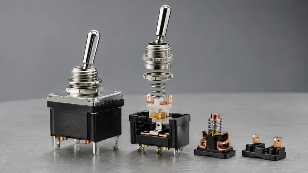
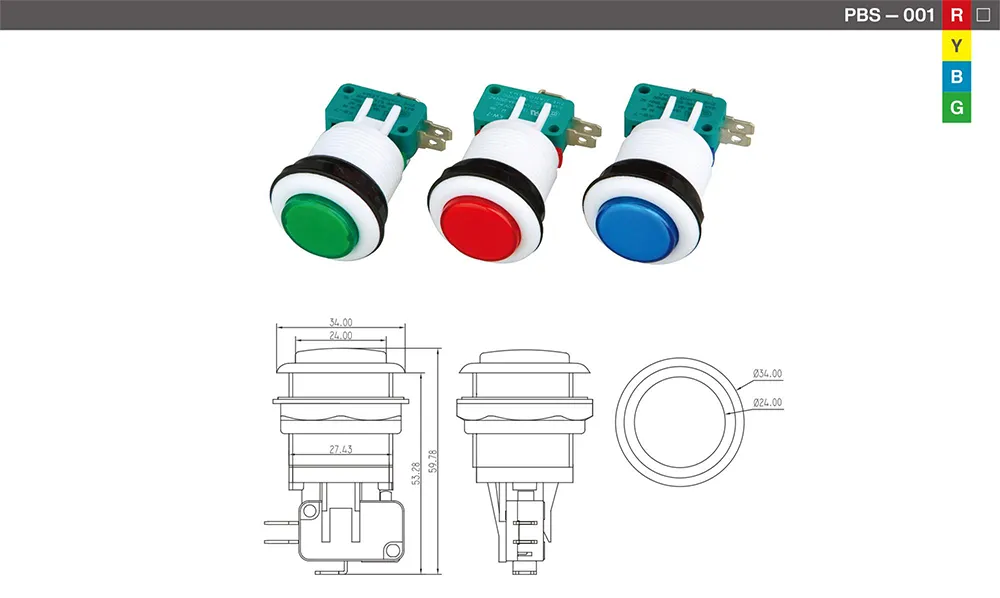
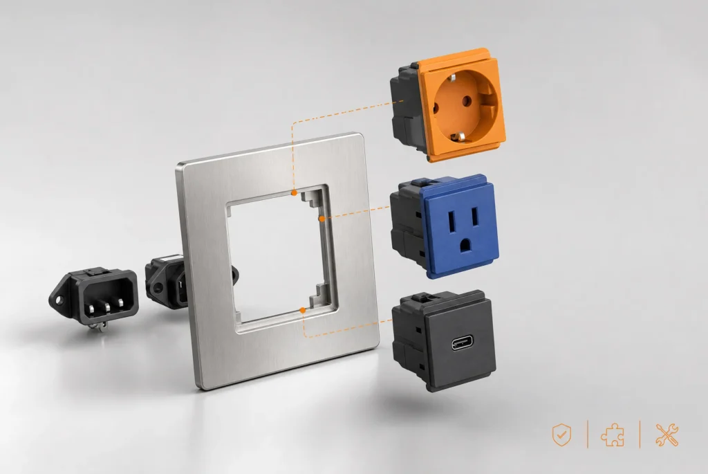
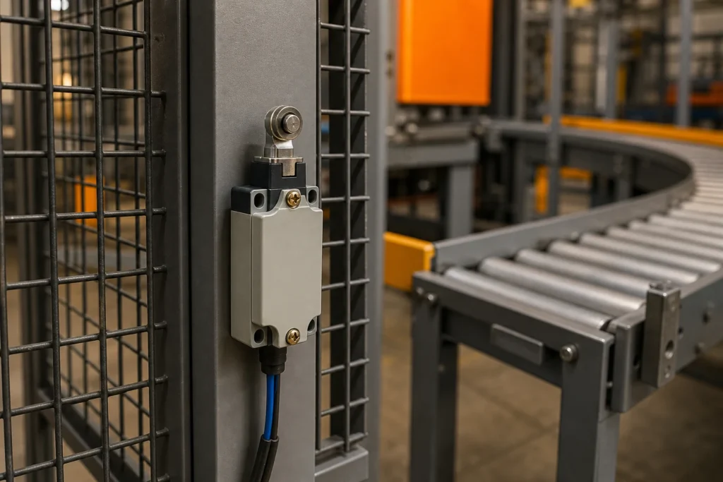
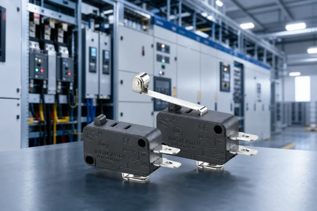
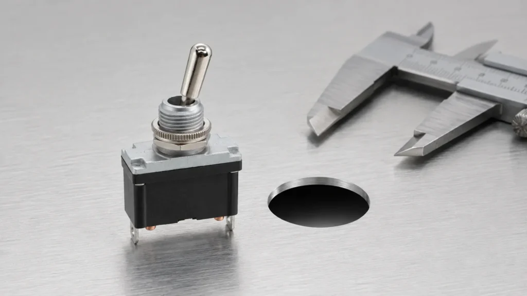
toggle switch hole size became a priority because Google Search Console already shows real impressions for this topic on LEMA. That signal indicates an existing audience, but the previous site coverage did not fully match the question. This guide turns the query into a practical selection, integration and purchasing workflow for equipment designers, panel builders, maintenance teams and industrial buyers. Toggle switch hole size is not a universal number. The required opening follows the bushing diameter or snap-in body, anti-rotation feature, panel thickness, washer stack and permitted tolerance of the exact model. A nominal thread designation is not a finished cutout instruction. Use the supplier drawing, measure approved samples, and make a trial coupon in the real panel material and coating stack. Check rear clearance for terminals and wiring, lever clearance at every position, and tool access for the mounting nut. For sealed models, the hole edge and gasket compression are part of the ingress path. Application view showing practical integration points for toggle switch hole size. What toggle switch hole size means in a real design A useful specification begins with behavior, not a catalogue photo. Write down what moves, what the operator or machine is trying to achieve, when the electrical state must change, and what should happen if a conductor opens or the device fails to reset. Separate the field device from the controller logic: a switch reports or commands a state, while the relay, PLC or control circuit decides how the machine responds. Similar product families often contain several contact arrangements, actuator styles, terminal forms and mounting versions. The family name helps discovery but does not define a production part. Use the complete model suffix, revision-controlled...
Read More