LEMA NEWS CENTER

News & Blog

News Center

Selecting a Metal Toggle Switch for the Panel Environment
Blog LEMA Electric

Selecting a Metal Toggle Switch for the Panel Environment

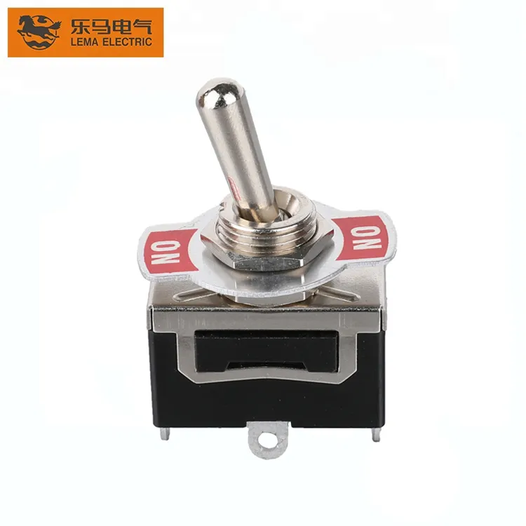
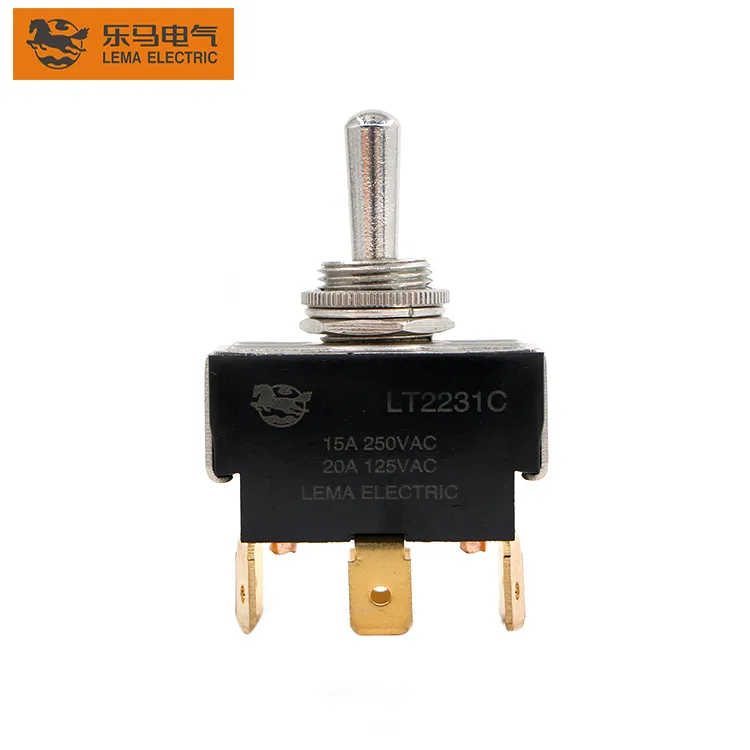
Metal housing is an input to review, not proof that a toggle is ready for every environment. Define the panel material, finish expectation, exposure, rear access and terminal process before a buyer treats a metal toggle as a final selection. Important: do not infer corrosion, ingress, current rating, approval or life performance from housing appearance. Confirm those boundaries with selected-model documentation. Source note: IEC 61058-1 publication scope and selected-model documentation. - FAQs ContentsPart 1. What does metal housing change in a toggle selection?Part 2. Which finish and panel inputs should an OEM document?Part 3. How should exposure be separated from unsupported sealing claims?Part 4. Which mounting and service-access checks matter?Part 5. Why must terminal and load review stay separate?Part 6. What should be validated before sample approval?Part 7. How can LEMA support a metal-toggle inquiry?Part 1. What does metal housing change in a toggle selection? A metal housing changes the interface discussion: panel contact, finish compatibility, bushing retention, grounding considerations where applicable, and service access. It does not collapse the electrical, environmental and approval checks into one material decision. Treat the housing as one field in a controlled selection file. Decision fieldRecord in the packageSend with quotePanelMaterial, thickness, coating and cutoutYesExposureIndoor/outdoor, cleaning, contamination and temperature contextYesMountingHardware stack, clearance and service accessYesElectricalLoad, terminal process and circuit formYes Use the LEMA Toggle Switch product line as a navigation starting point after the selection file is complete. Part 2. Which finish and panel inputs should an OEM document? Specify the actual panel material and coating stack, not just a color. A plated, painted or stainless front has different assembly and service questions from an uncoated steel panel. Document any cosmetic zone, marking requirement,...

Read More
Planning an OEM Harness Around a Screw Terminal Toggle Switch
Blog LEMA Electric

Planning an OEM Harness Around a Screw Terminal Toggle Switch

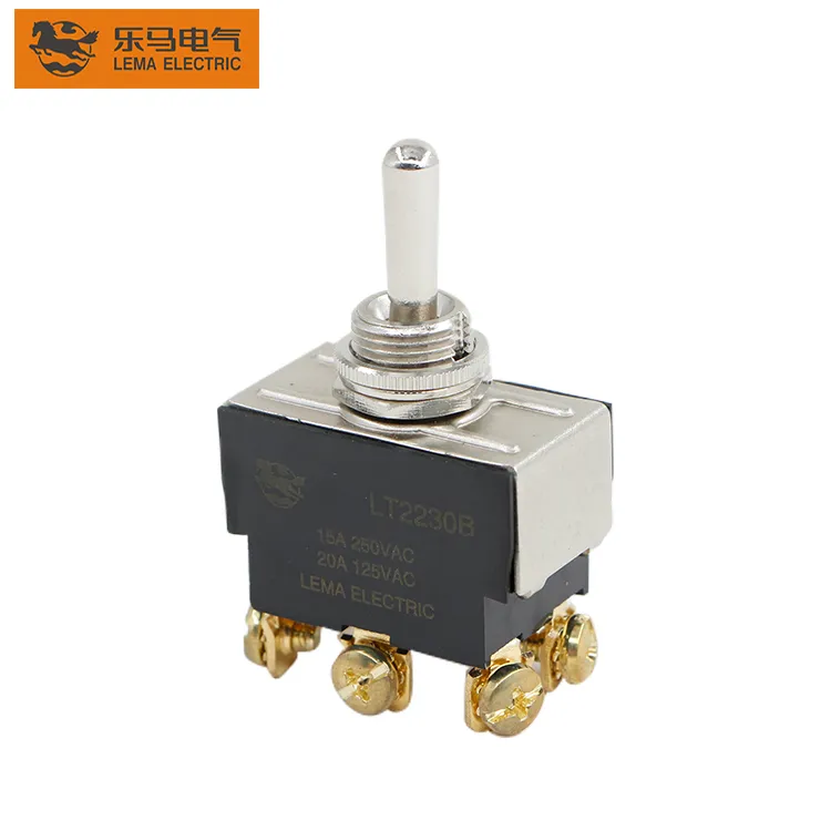
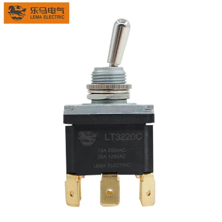
A screw-terminal toggle is only as reliable as the drawing and process around it. Put the conductor, termination style, rear access, inspection method and service label into one controlled package before a buyer approves samples. Important: a familiar screw head does not establish torque, current capacity, environmental suitability or approval. Those limits must come from the selected-model documentation. Source note: IEC 61058-1 publication scope and selected-model documentation. - FAQs ContentsPart 1. What changes when an OEM specifies screw terminals?Part 2. Which conductor and terminal inputs belong in the drawing?Part 3. How should access and clearance be planned?Part 4. Which assembly and inspection controls prevent rework?Part 5. How should service and change control be documented?Part 6. What should be validated before a harness release?Part 7. How can LEMA support a screw-terminal inquiry?Part 1. What changes when an OEM specifies screw terminals? Screw terminals move the decision beyond circuit form. The engineering file must state the conductor construction, whether an end treatment is required, access for the tool, the rear-space envelope, and how the operator or inspector knows the connection is complete. This prevents purchasing from choosing by photo or terminal count alone. Decision fieldRecord in the packageSend with quoteDutyVoltage, load type, steady current and inrushYesHarnessConductor, insulation, routing and termination methodYesPanelCutout, thickness and rear accessYesServiceLabel, inspection point and replacement ruleYes Start at the LEMA Toggle Switch product line after the application file exists. Part 2. Which conductor and terminal inputs belong in the drawing? Use the exact drawing revision for terminal positions, then identify the wire and the route that reaches each connection. Keep the load path beside the terminal designation so the assembly team does not infer it from color alone....

Read More
Planning Cutout and Clearance for Panel Mount Toggles
Blog LEMA Electric

Planning Cutout and Clearance for Panel Mount Toggles

Panel-mount toggles fail in production when cutout and clearance stay verbal. Put hole size, thickness, and rear space on one drawing before the punch program. A correct circuit form still scrap panels when the bushing cannot seat. Important: Treat cutout and clearance as drawing-controlled installation inputs, not shop rules of thumb. Confirm bushing and hardware against selected-model documentation before tooling. Source note: IEC 61058-1 publication scope and selected-model documentation. - FAQs ContentsPart 1. Which cutout dimensions belong on the mounting drawing?Part 2. How should panel thickness and hardware stack be recorded?Part 3. What rear and lever clearances prevent installation failures?Part 4. How do labels, boots, and guards change the envelope?Part 5. Which electrical notes still travel with the cutout file?Part 6. How should panel-mount installs be validated before tooling?Part 7. How can LEMA support a panel-mount toggle inquiry?Part 1. Which cutout dimensions belong on the mounting drawing? Record the bushing diameter, tolerance, and anti-rotation feature callouts the model drawing requires. Guessing a “standard toggle hole” creates ovalized panels and spinning switches. Decision fieldInput to documentSend with quote CutoutDiameter / shape and toleranceYes — mounting drawing Panel thicknessMaterial and stack-upYes — thickness note ClearanceRear depth and lever swingYes — envelope sketch HardwareNut, lockwasher, keyway needsYes — hardware list Browse the LEMA Toggle Switch product line after the cutout sheet exists. Part 2. How should panel thickness and hardware stack be recorded? Panel thickness controls thread engagement and whether optional boots or nameplates still fit. Note paint or overlay thickness so the final stack matches the sample that will be approved. Compact dashboards may also use the mini panel-mount selection article when space, not only hole size, drives the family choice. Part...

Read More
Reviewing Current Rating on a Heavy Duty Toggle Switch
Blog LEMA Electric

Reviewing Current Rating on a Heavy Duty Toggle Switch

“Heavy duty” is a duty description, not a substitute for a printed current rating. Capture voltage, load type, and inrush first, then compare those notes to selected-model documentation. Brochure adjectives alone do not clear a panel release. Important: Never transfer a catalog amp claim onto a LEMA model without the quoted datasheet. Keep rating language tied to selected-model documentation. Source note: IEC 61058-1 publication scope and selected-model documentation. - FAQs ContentsPart 1. What does heavy duty mean on a toggle RFQ?Part 2. Which current and load-type inputs belong in the file?Part 3. How should inrush and duty cycle reshape the review?Part 4. Which terminal and panel checks sit beside the rating?Part 5. When does sealing become a parallel requirement?Part 6. How should OEMs validate rating assumptions before release?Part 7. How can LEMA support a heavy-duty toggle inquiry?Part 1. What does heavy duty mean on a toggle RFQ? Write the operator load in engineering units before shopping by handle size. Heavy-duty intent usually means higher continuous current, inductive make, or harsher mechanical abuse—not merely a larger lever. Decision fieldInput to documentSend with quote Electrical dutyVoltage, steady current, load typeYes — duty summary InrushMake current and frequencyYes — inrush note TerminalsScrew, QC, or solder processYes — termination plan PanelCutout, thickness, clearanceYes — mounting envelope Start public browsing at the LEMA Toggle Switch product line after the duty file exists. Part 2. Which current and load-type inputs belong in the file? Separate resistive, inductive, and lamp loads on the worksheet. A rating that looks comfortable for steady resistive current may still be wrong for motor or transformer make. Dual-pole high-load panels should also complete the DPDT dual-circuit selection map so each pole carries...

Read More
Selecting a DPDT Toggle Switch for Dual-Circuit Panels
Blog LEMA Electric

Selecting a DPDT Toggle Switch for Dual-Circuit Panels

DPDT hardware is a two-pole assignment problem, not a thicker SPDT. Write what each pole switches, then request samples. Unused contacts still confuse harness teams when the drawing stays silent. Important: Do not treat DPDT as a flexible upgrade label for any multi-screw toggle. Confirm both poles against selected-model documentation before panel release. Source note: IEC 61058-1 publication scope and selected-model documentation. - FAQs ContentsPart 1. When does a panel truly need DPDT instead of SPDT?Part 2. How should both poles be documented on one schematic?Part 3. Which maintained states still must be printed on the BOM?Part 4. How do cutout and clearance checks change with dual poles?Part 5. How should load notes stay tied to each pole?Part 6. How should dual-circuit panels be validated before release?Part 7. How can LEMA support a DPDT panel inquiry?Part 1. When does a panel truly need DPDT instead of SPDT? Choose DPDT when two circuits must change state together—or when isolation between poles is required by the schematic. A single SPDT cannot honestly carry two independent loads. Decision fieldInput to documentSend with quote Pole mapLoad on pole A and pole BYes — dual-path schematic Circuit formMaintained states per poleYes — printed form Isolation needWhy poles must stay separateYes — design note Panel fitCutout and clearanceYes — mounting drawing Index families from the LEMA Toggle Switch product line after the pole map exists. Part 2. How should both poles be documented on one schematic? Draw both commons and their throws on one sheet. Shared lever motion does not excuse missing contact labels; each pole needs a pin map the harness can follow. If the team is still identifying a single-pole common, finish the SPDT...

Read More
Identifying SPDT Toggle Switch Terminals for OEM Wiring
Blog LEMA Electric

Identifying SPDT Toggle Switch Terminals for OEM Wiring

SPDT wiring fails when teams guess terminals from a lever photo. Lock the common and each throw on the schematic first, then assign harness pins. A clean panel still misbehaves when C and throw labels drift between drawing revisions. Important: Treat SPDT terminal identity as a drawing-controlled field, not a shop-floor nickname. Confirm contact paths against selected-model documentation before harness release. Source note: IEC 61058-1 publication scope and selected-model documentation. - FAQs ContentsPart 1. Which terminals define an SPDT toggle on the drawing?Part 2. How should common and throw pins be labeled in the harness?Part 3. When does SPDT wiring differ from simple ON-OFF slang?Part 4. Which load and panel notes still belong beside the pin map?Part 5. How do OEMs prevent terminal swaps during service?Part 6. How should SPDT wiring be validated before release?Part 7. How can LEMA support an SPDT wiring inquiry?Part 1. Which terminals define an SPDT toggle on the drawing? Start from the contact diagram: one common (C / COM) and two throws that the lever selects. Record which throw is ON in each maintained position and whether a center-off exists. Decision fieldInput to documentSend with quote Terminal mapC / throw labels on the drawingYes — labeled schematic Circuit formMaintained states the SPDT must expressYes — printed form Load pathWhich throw carries which loadYes — duty summary Panel fitCutout, thickness, clearanceYes — mounting envelope Browse the LEMA Toggle Switch product line only after the pin map exists. Part 2. How should common and throw pins be labeled in the harness? Harness labels should mirror the drawing characters exactly. If manufacturing uses color codes, keep a cross-reference table in the same package so service teams do not...

Read More
Selecting an Automotive Dashboard Toggle Switch
Blog LEMA Electric

Selecting an Automotive Dashboard Toggle Switch

An automotive dashboard toggle decision starts with the 12V accessory circuit, not a chrome lever. Document DC load and inrush, circuit form, cutout, and harness method before requesting samples for a vehicle or mobile-equipment panel. Important: A 12V panel label does not prove DC accessory suitability for lamps, motors, or inductive loads. Confirm voltage, current, inrush, and load type against selected-model documentation. Source note: IEC 61058-1 publication scope and selected-model documentation. - FAQs ContentsPart 1. What makes a dashboard toggle different from a generic panel switch?Part 2. How should 12V DC load and inrush be documented?Part 3. Which circuit forms fit vehicle accessory panels?Part 4. Which cutout and finish inputs control dash fit?Part 5. How should harness and vibration notes be captured?Part 6. How should dashboard toggles be validated before release?Part 7. How can LEMA support a dashboard toggle inquiry?Part 1. What makes a dashboard toggle different from a generic panel switch? Dashboard and mobile-equipment panels add vibration, limited depth, and operator gloves to ordinary panel rules. Appearance still does not prove DC contact suitability. Decision fieldInput to documentSend with quote DC load12V steady current and inrushYes — accessory duty Circuit formON-OFF, ON-OFF-ON, momentaryYes — state map CutoutHole, thickness, finish stackYes — dash drawing HarnessTerminal style and strain reliefYes — wiring note General low-voltage framing is expanded in the 12V OEM panel toggle planning guide. Browse families via the LEMA Toggle Switch product line. Part 2. How should 12V DC load and inrush be documented? Record lamp, motor, solenoid, or heater behavior at 12V DC. Cold inrush and inductive kick are the usual reasons a “12V” label disappoints in the field. Load noteCaptureRisk if missed ResistiveSteady currentOverstated margin Motor /...

Read More
Selecting a Mini Toggle Switch for Panel Mounting
Blog LEMA Electric

Selecting a Mini Toggle Switch for Panel Mounting

A mini toggle wins space only when the mounting envelope and load stay honest. Document cutout, rear clearance, and duty before treating a small body as a drop-in for a full-size control. Important: Compact body size does not prove cutout, panel thickness, or rear clearance. Confirm the model drawing against the panel stack before tooling. Source note: IEC 61058-1 publication scope and selected-model documentation. - FAQs ContentsPart 1. When is a mini toggle the right panel choice?Part 2. Which cutout and bushing inputs control front fit?Part 3. How should rear clearance and harness bends be planned?Part 4. How do load and circuit form stay realistic at mini size?Part 5. Which terminal styles fit compact assemblies?Part 6. How should mini panel toggles be validated?Part 7. How can LEMA support a mini-toggle inquiry?Part 1. When is a mini toggle the right panel choice? Mini toggles suit dense operator panels, handheld enclosures, and instruments where a full-size bushing will not fit. They are a poor shortcut for high-inrush loads that need a larger contact system. Decision fieldInput to documentSend with quote EnvelopeFront and rear space limitsYes — section view CutoutHole size and panel thicknessYes — mounting callout LoadVoltage, current, inrushYes — duty summary LogicCircuit formYes — state note Family browsing starts at the LEMA Toggle Switch product line. Part 2. Which cutout and bushing inputs control front fit? Confirm bushing thread and hole size from the model drawing. Compact hardware stacks leave less forgiveness for oversized holes or thick panels. Three-position mini packages still need a full state map; see the 3-position center-off selection guide. Part 3. How should rear clearance and harness bends be planned? Rear clearance is where mini programs fail....

Read More
Reviewing Seals and Terminals on an IP67 Waterproof Toggle Switch
Blog LEMA Electric

Reviewing Seals and Terminals on an IP67 Waterproof Toggle Switch

An IP67 waterproof toggle switch is a sealing problem before it is a catalog label. Define the front-panel seal path, rear terminal exposure, washdown chemistry, mounting stack, and test method before requesting a model review. A stamped IP code does not describe an unfinished harness exit. Important: IP67 marks a defined dust and temporary-immersion test envelope. It does not by itself prove continuous underwater operation or chemical washdown resistance. Source note: IEC 60529 publication scope; confirm seal path and test method in the selected model documentation. ContentsPart 1. What does an IP67 claim cover on a toggle?Part 2. Which seal paths protect the front of the panel?Part 3. How should rear terminals and harness exits be treated?Part 4. Why must washdown chemistry be listed separately?Part 5. How does the mounting stack affect sealing?Part 6. How should sealing be validated before release?Part 7. How can LEMA support a waterproof toggle inquiry?Part 1. What does an IP67 claim cover on a toggle? IP67 is an enclosure test class for dust and temporary immersion under defined conditions. It is not a license for continuous underwater operation, and it does not automatically cover detergents, oils, or steam. Write the exposure target and the test method the project will accept. Claim languageWhat to verifyCommon overreadIP67Dust and temporary immersion envelope“Works underwater forever”WaterproofWhich surfaces are sealedWhole product including open terminalsWashdown readyPressure, angle, chemistryEquating water IP with chemical resistance Family options sit under the LEMA Toggle Switch product line; sealing still follows the selected model documentation. Part 2. Which seal paths protect the front of the panel? Front sealing usually combines a lever boot, bushing o-rings or washers, and a case-to-cover seal. Each interface is a leak path...

Read More
Selecting a 12V Toggle Switch for OEM Control Panels
Blog LEMA Electric

Selecting a 12V Toggle Switch for OEM Control Panels

A 12V toggle switch decision starts with the panel circuit, not a voltage sticker. Define the switch function, DC load and inrush, cutout, terminals, and validation plan before requesting a model review. Similar levers can hide different contact forms and DC limits. Important: A 12V label or an AC amp printed for another voltage class does not prove DC accessory suitability. Confirm voltage, current, load type, and inrush against the selected model documentation before release. Source note: IEC 61058-1 publication scope and selected-model documentation. ContentsPart 1. What control job must the 12V toggle perform?Part 2. How do ON-OFF, ON-OFF-ON, and momentary functions differ?Part 3. How should DC load and inrush be documented?Part 4. Which panel cutout and clearance inputs control fit?Part 5. How should terminal style match the harness plan?Part 6. How is a 12V panel switch validated before release?Part 7. How can LEMA support a 12V toggle inquiry?Part 1. What control job must the 12V toggle perform? Write the operator action and the electrical result first. Note whether the switch must stay in position, return automatically, or select between two live paths. That description prevents buying a convenient lever that cannot express the required logic. Decision fieldInput to documentWhy it mattersFunctionMaintained or momentary statesControls circuit formLoadSteady current and inrush at 12V DCFrames contact reviewPanelCutout, thickness, rear clearanceControls mechanical fitHarnessTerminal style and conductor sizeControls production wiring Public family options are indexed in the LEMA Toggle Switch product line; the drawing still owns the selection. Part 2. How do ON-OFF, ON-OFF-ON, and momentary functions differ? ON-OFF is a simple maintained path. ON-OFF-ON adds a center or alternate maintained path. Momentary positions spring back and suit test or jog duties. Mixing these...

Read More
Selecting a Waterproof Toggle Switch Boot
Blog LEMA Electric

Selecting a Waterproof Toggle Switch Boot

A waterproof toggle boot is a matched seal accessory, not a universal rubber cap. Match bushing thread, panel face, and exposure intent first. Only then request a sealed-series review against the assembly drawing. Important: A rubber boot does not automatically deliver a rated ingress result. Confirm bushing fit, chemistry, and the sealed series documentation before washdown duty. Source note: NKK M series waterproof toggle datasheet and IEC 61058-1 publication scope. - FAQs ContentsPart 1. What job does a waterproof toggle boot perform?Part 2. How should bushing thread and panel stack be matched?Part 3. Which exposure and cleaning notes belong in the RFQ?Part 4. How do boots interact with guards and legends?Part 5. Which assembly mistakes break the seal in production?Part 6. How should booted toggles be validated?Part 7. How can LEMA support a waterproof-boot inquiry?Part 1. What job does a waterproof toggle boot perform? Boots protect the lever opening and help the panel gasket story when splash, wash-down spray, or dust is present at the front face. They do not automatically define an IP result for the whole enclosure. Decision fieldInput to documentSend with quote BushingThread / diameter from drawingYes — bushing callout Panel stackThickness and gasket faceYes — section view ExposureSplash, wash, dust, chemicalsYes — environment note Circuit formMaintained or momentary statesYes — logic note Sealed family browsing starts at the LEMA Toggle Switch product line and the waterproof series route below. Part 2. How should bushing thread and panel stack be matched? Most boot failures start at the thread and bushing interface. Confirm the boot against the selected bushing, nut stack, and panel thickness rather than ordering by a nominal “standard toggle” label. For sealed-switch context beyond the...

Read More
Selecting a Toggle Switch Safety Cover or Guard
Blog LEMA Electric

Selecting a Toggle Switch Safety Cover or Guard

A safety cover or guard is a panel geometry decision, not a sticker on the BOM. Define the accidental-actuation risk, how the operator must open the cover, and the swing envelope before locking a switch and accessory pair. Important: A cover or guard does not create a safety function by itself. Confirm actuator access, lockout needs, and seal stack against the panel drawing. Source note: IEC 61058-1 publication scope and selected-model documentation. - FAQs ContentsPart 1. When does a toggle need a safety cover or guard?Part 2. How do cover styles change operator access?Part 3. Which panel clearance inputs control fit?Part 4. How do boots and covers interact on sealed panels?Part 5. Which labeling and service notes belong on the drawing?Part 6. How should covered toggles be validated?Part 7. How can LEMA support a covered-toggle inquiry?Part 1. When does a toggle need a safety cover or guard? Covers and guards belong on toggles that can start motion, apply power, or change modes when brushed by clothing, tools, or vibration. Decision fieldInput to documentSend with quote Risk noteWhat accidental throw causesYes — hazard summary Cover styleFlip, lift, lockable, or shroudYes — accessory preference ClearanceSwing and adjacent controlsYes — envelope drawing Switch dutyCircuit form and loadYes — electrical summary Browse families via the LEMA Toggle Switch product line after the risk note exists. Part 2. How do cover styles change operator access? Flip covers slow casual bumps but still allow trained access. Lockable guards raise the bar for intentional operation. Deep shrouds reduce side hits but can complicate gloved use. Match cover behavior to the operator script used in the 12V OEM panel toggle planning context when the panel is low-voltage accessory...

Read More