LEMA NEWS CENTER

News & Blog

News Center

Hoist Limit Switch Guide: Travel Detection, Over-Travel and Selection
Blog LEMA Electric

Hoist Limit Switch Guide: Travel Detection, Over-Travel and Selection

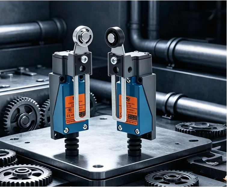
A hoist limit switch detects when lifting equipment approaches a defined travel boundary and sends a signal to the hoist control system. Upper travel limiting helps prevent the hook block or load-handling device from moving into an unsafe mechanical condition, but the switch alone does not guarantee a safe stop. The complete result depends on the sensing method, actuator setup, controller logic, contactor or drive response, brake condition, stopping distance, inspection and applicable crane or hoist requirements. Operational and final over-travel limits may have different roles. Selection must therefore begin with the hoist design and risk assessment, not with a switch image or a generic current rating.Different actuators require different approach geometry and travel allowance. Operational limit versus final over-travel protectionAn operational upper limit normally stops routine upward travel before the mechanism enters the final prohibited region. A separate final limit, where required by the equipment design or applicable rules, provides another layer if normal travel control fails or is bypassed. These functions should not be casually combined in one adjustable point. The design must define which motion is interrupted, how reset occurs, whether lowering remains available, and what inspection is required after a final limit operates.Stopping distance matters. The hook block continues moving during detection, control processing, contactor or drive response and brake application. Load, speed, reeving, brake condition and mechanical elasticity influence the final stopping position. Set the actuator with verified margin under the equipment manufacturer's procedure and test first at slow speed without relying on a person standing near the hazard. How does the switching mechanism work?The target contacts a plunger, lever, roller, rod or cam. Mechanical travel is transferred to an internal snap-action or switching mechanism,...

Read More
Consolidating Micro Switch Variants Across Appliance Lines
Blog LEMA Electric

Consolidating Micro Switch Variants Across Appliance Lines

Appliance platforms collect micro switch variants the way drawers collect cables. Each program adds one more lever, force, or terminal option until purchasing manages dozens of near-duplicates. Consolidation starts with an inventory, not with a favorite part number. ContentsPart 1. Why do appliance platforms accumulate switch variants?Part 2. How should switch points be inventoried?Part 3. How do duty profiles define consolidation groups?Part 4. Which actuator and terminal standards help most?Part 5. How should validation cover a consolidation?Part 6. What belongs in the RFQ and Fit Boundary?Part 7. How can LEMA support a consolidation inquiry?FAQsReferencesPart 1. Why do appliance platforms accumulate switch variants? Variant growth is organic: separate design teams, separate launch dates, and separate suppliers each solve a local problem. Nobody chooses thirty part numbers; portfolios drift there. Growth driverTypical resultConsolidation leverPer-program sourcingSame duty, different brandsCommon series with option codesCopy-paste with editsSlightly different leversStandard actuator menuTerminal convenienceMixed solder and quick-connectHarness-level terminal standard Anchor the exercise in a documented catalog such as the LEMA Micro Switch product line, where option codes make overlap visible. Part 2. How should switch points be inventoried? List every point across washers, dryers, ovens, dishwashers, and small appliances in one table: function, contact state, load, travel, environment, and annual volume. The inventory is the deliverable; opinions about similarity come later. Two published examples show the level of detail worth capturing per point: the refrigerator door switch guide and the water heater interlock guide. Part 3. How do duty profiles define consolidation groups? Group by duty profile: signal-level sensing, lamp and indicator loads, motor and heater interlocks, and wet-area points. Products differ; duties repeat. Signal points share dry-circuit contact needs.Power interlocks share inrush and rating review.Wet or...

Read More
Selecting a Door Position Switch for Lift Equipment
Blog LEMA Electric

Selecting a Door Position Switch for Lift Equipment

Door Limit Switch for Lifts selection begins with the installed mechanism and the real control input. Record door travel, target position, actuator direction, mounting tolerance, and controller contact logic before asking for a model review. This is component selection for position and travel detection only. It does not claim a lift locking device, regulatory compliance, or completed safety redundancy. ContentsPart 1. What does a door limit switch do in lift equipment?Part 2. How should door travel and target positions be defined?Part 3. Which actuator and mounting details matter?Part 4. How should contact logic and controller inputs be reviewed?Part 5. What should installation validation cover?Part 6. What belongs in the RFQ and Fit Boundary?Part 7. How can LEMA support a lift-door inquiry?FAQsReferencesPart 1. What does a door limit switch do in lift equipment? Start with the required position signal, not the product label. The application drawing should show the moving feature, the state to be reported, and the consequence of a missed or early signal. Use the LEMA Limit Switch product line as a category route, then compare the final candidate with its model documentation. Selection fieldInput to documentWhy it mattersPositionTarget point and toleranceDefines the required signal windowMechanismApproach, travel, clearance, and side loadControls actuation repeatabilityCircuitContact state, voltage, load, and interfaceFrames electrical reviewEnvironmentContamination, vibration, temperature, and service accessFrames validation conditions Part 2. How should door travel and target positions be defined? Translate the motion into measurable positions. Identify the normal approach direction, the operating window, the release path, and every tolerance that can move the trip point. A layout review should also record whether adjustment is available and who controls it during installation. For a roller-driven mechanism, the roller limit switch applications...

Read More
Planning Micro Switches for Medical Device Interfaces
Blog LEMA Electric

Planning Micro Switches for Medical Device Interfaces

Medical equipment asks more of a small switch than most panels do. Operator feel must stay consistent, housings meet aggressive wipe-down chemistry, and the switched circuit is often a milliamp controller input. Plan those three demands together from the first drawing. ContentsPart 1. What roles do micro switches play in medical devices?Part 2. How should force and feel be specified?Part 3. How does cleaning chemistry affect the housing?Part 4. Why do signal-level loads need extra care?Part 5. Which validation steps fit device development?Part 6. What belongs in the RFQ and Fit Boundary?Part 7. How can LEMA support a medical equipment inquiry?FAQsReferencesPart 1. What roles do micro switches play in medical devices? Detection and interface tasks dominate: lid and cassette position on analyzers, handpiece triggers, bed and lift position feedback, and enclosure interlocks on carts and pumps. Almost all of them feed logic rather than power. Device areaSwitch taskDesign emphasisAnalyzer lid or trayPosition confirmationRepeatable operating pointHand controlsOperator triggerForce and acoustic feelMobile equipmentDock and panel detectionTolerance to housing flexEnclosuresService interlockDefined free-state behavior Shortlist families through the LEMA Micro Switch product line, keeping the interface drawing beside the catalog rather than after it. Part 2. How should force and feel be specified? Force specification needs a window, not a single number: the minimum that prevents accidental actuation and the maximum an operator can comfortably repeat. Acoustic and tactile character belong in the same note, because clinical users notice a changed click sooner than most. Compact envelopes tighten these choices further; the miniature switch packaging guide covers the packaging side of the same decision. Part 3. How does cleaning chemistry affect the housing? Wipe-down agents attack plastics and seals over hundreds of cycles, not...

Read More
Planning Cam Positions and Circuits With a Rotary Limit Switch
Blog LEMA Electric

Planning Cam Positions and Circuits With a Rotary Limit Switch

Rotary Limit Switch selection begins with the installed mechanism and the real control input. Record cam positions, shaft direction, switch sequence, dwell, and allowable travel before asking for a model review. It does not establish a safety function, prove a model-specific rating, or replace control-system validation. ContentsPart 1. What should a rotary limit switch control?Part 2. How should cam positions and circuit sequence be defined?Part 3. Which mechanical inputs control repeatable actuation?Part 4. How should circuit duty be reviewed?Part 5. What must be checked during installation and validation?Part 6. What belongs in the RFQ and Fit Boundary?Part 7. How can LEMA support a rotary-control inquiry?FAQsReferencesPart 1. What should a rotary limit switch control? Start with the required position signal, not the product label. The application drawing should show the moving feature, the state to be reported, and the consequence of a missed or early signal. Use the LEMA Limit Switch product line as a category route, then compare the final candidate with its model documentation. Selection fieldInput to documentWhy it mattersPositionTarget point and toleranceDefines the required signal windowMechanismApproach, travel, clearance, and side loadControls actuation repeatabilityCircuitContact state, voltage, load, and interfaceFrames electrical reviewEnvironmentContamination, vibration, temperature, and service accessFrames validation conditions Part 2. How should cam positions and circuit sequence be defined? Translate the motion into measurable positions. Identify the normal approach direction, the operating window, the release path, and every tolerance that can move the trip point. A layout review should also record whether adjustment is available and who controls it during installation. For a roller-driven mechanism, the roller limit switch applications guide can help frame the actuator-path discussion. It does not replace the drawing and model review for this application....

Read More
Selecting Micro Switches for HVAC Airflow Interlocks
Blog LEMA Electric

Selecting Micro Switches for HVAC Airflow Interlocks

HVAC equipment uses micro switches as position eyes on moving air-path parts. Damper end positions, filter and panel access doors, condensate float arms, and fan interlocks all reduce to one question: does the circuit change state reliably in a dusty, sometimes wet airstream? ContentsPart 1. Where do micro switches sit in HVAC equipment?Part 2. How should damper and door travel be defined?Part 3. How do dust and condensation shape selection?Part 4. Which load and controller inputs matter?Part 5. Which installation and service checks prevent callbacks?Part 6. What belongs in the RFQ and Fit Boundary?Part 7. How can LEMA support an HVAC inquiry?FAQsReferencesPart 1. Where do micro switches sit in HVAC equipment? Air handlers and rooftop units scatter switch points across the cabinet. Each point has its own motion, environment, and electrical duty, so listing them explicitly beats treating the unit as one application. Switch pointMotion sensedPrimary stressDamper end positionBlade or linkage travelDust loading on the actuatorAccess door interlockPanel open and closeMisalignment and slam energyCondensate floatFloat arm riseHumidity and condensationFan section interlockGuard or vane positionVibration through the frame Map each point to a candidate family through the LEMA Micro Switch product line before fixing any bracket design. Part 2. How should damper and door travel be defined? Damper blades and access doors rarely stop at identical positions across builds. The drawing must state where in the travel the circuit changes state, plus the overtravel available past that point. The same tolerance-stack discipline used for industrial panel selection applies here: free position, operating position, release point, and maximum travel, all dimensioned against the bracket. Part 3. How do dust and condensation shape selection? Airstreams carry filter dust, fibers, and moisture directly to...

Read More
Magnetic Limit Switch Position Feedback for Gate Openers
Blog LEMA Electric

Magnetic Limit Switch Position Feedback for Gate Openers

Magnetic Limit Switch for Gate Opener decisions begin with the installed mechanism, not a catalogue label. Define the actuator path, circuit duty, environment, mounting, and validation target before requesting a final model review. Similar-looking parts can have different operating windows, terminals, and documented limits. ContentsPart 1. Define the position-feedback jobPart 2. Map travel and mountingPart 3. Set the environmental boundaryPart 4. Document circuit dutyPart 5. Plan validation and fitPart 6. Route a documented inquiryFAQsReferencesPart 1. Define the position-feedback job Describe the state that must change, the moving feature that creates it, and the consequence of a late, early, or missing signal. This keeps a mechanical position question separate from assumptions about a particular series. Decision fieldInput to documentWhy it mattersFunctionFree and operated statesPrevents reversed control logicMechanismTravel, force, and side loadControls repeatable actuationCircuitVoltage, current, load, and inrushFrames contact reviewEnvironmentContamination, vibration, service accessFrames validation Part 2. Map travel and mounting Put free position, operating position, release, maximum travel, and bracket tolerances on one drawing. The same drawing should identify the approach direction and any side load transferred by a cam, button, linkage, magnet, or stop. Use the industrial micro switch selection guide when the mechanical interface also needs a broader panel review. Part 3. Set the environmental boundary Translate site conditions into exposure inputs: dust, splash, cleaning method, temperature variation, vibration, cable movement, and access for service. A surrounding enclosure does not establish the capability of every component interface inside it. Record the target exposure and the test method rather than inferring a result from a product family name. Part 4. Document circuit duty Contact suitability depends on the actual circuit. Capture voltage, current, load type, inrush, switching frequency, and controller input...

Read More
Wiring a Double Pole Micro Switch in Appliance Control
Blog LEMA Electric

Wiring a Double Pole Micro Switch in Appliance Control

A double pole micro switch changes two separate circuits with one snap action. That single mechanical event can open line and neutral together, or drive a load and its indicator in step. Wire it from a two-circuit drawing, never from terminal appearance. ContentsPart 1. What does double pole mean in a micro switch?Part 2. Which appliance scenarios need two switched circuits?Part 3. How should both circuits be drawn before wiring?Part 4. Which terminal and simultaneity checks matter?Part 5. How does load per pole change the review?Part 6. What belongs in the RFQ and Fit Boundary?Part 7. How can LEMA support a double pole inquiry?FAQsReferencesPart 1. What does double pole mean in a micro switch? Double pole construction places two contact sets on one common actuator. Each pole keeps its own terminals and its own circuit, while the mechanism forces both to change state in the same actuation. ConfigurationPolesTypical useSPST / SPDTOneSingle sensing or control pathDPSTTwo, on-offSwitching two conductors togetherDPDTTwo, changeoverTwo circuits that each need NO and NC paths Confirm the configuration code against the LEMA Micro Switch product line documentation for the series in question, since families differ in which poles they offer. Part 2. Which appliance scenarios need two switched circuits? Appliance control creates the common cases. A door interlock may need to cut power and signal the controller in one motion, while a heating product may switch the element circuit and a status lamp together. Single-circuit examples of the same discipline appear in the refrigerator door switch guide, where one pole handles the sensing task alone. Part 3. How should both circuits be drawn before wiring? Draw each circuit end to end before touching terminals: source, load, protection,...

Read More
Selecting a Plunger Limit Switch for Machine-Tool Position Sensing
Blog LEMA Electric

Selecting a Plunger Limit Switch for Machine-Tool Position Sensing

Plunger Limit Switch decisions begin with the installed mechanism, not a catalogue label. Define the actuator path, circuit duty, environment, mounting, and validation target before requesting a final model review. Similar-looking parts can have different operating windows, terminals, and documented limits. ContentsPart 1. Define the position-feedback jobPart 2. Map travel and mountingPart 3. Set the environmental boundaryPart 4. Document circuit dutyPart 5. Plan validation and fitPart 6. Route a documented inquiryFAQsReferencesPart 1. Define the position-feedback job Describe the state that must change, the moving feature that creates it, and the consequence of a late, early, or missing signal. This keeps a mechanical position question separate from assumptions about a particular series. Decision fieldInput to documentWhy it mattersFunctionFree and operated statesPrevents reversed control logicMechanismTravel, force, and side loadControls repeatable actuationCircuitVoltage, current, load, and inrushFrames contact reviewEnvironmentContamination, vibration, service accessFrames validation Part 2. Map travel and mounting Put free position, operating position, release, maximum travel, and bracket tolerances on one drawing. The same drawing should identify the approach direction and any side load transferred by a cam, button, linkage, magnet, or stop. Use the industrial micro switch selection guide when the mechanical interface also needs a broader panel review. Part 3. Set the environmental boundary Translate site conditions into exposure inputs: dust, splash, cleaning method, temperature variation, vibration, cable movement, and access for service. A surrounding enclosure does not establish the capability of every component interface inside it. Record the target exposure and the test method rather than inferring a result from a product family name. Part 4. Document circuit duty Contact suitability depends on the actual circuit. Capture voltage, current, load type, inrush, switching frequency, and controller input behavior, then compare...

Read More
Matching Actuator Types to OEM Mechanism Motion
Blog LEMA Electric

Matching Actuator Types to OEM Mechanism Motion

Actuator choice is a motion-matching exercise, not a styling decision. Lever, roller lever, plunger, and button actuators translate the same snap mechanism to different travel directions, forces, and tolerances. Start from how the moving part approaches the switch, then keep the operating point stable. ContentsPart 1. How does an actuator change switch behavior?Part 2. When is a plain lever or long lever right?Part 3. When do roller actuators earn their cost?Part 4. How do plunger and button styles behave?Part 5. Which mounting and tolerance inputs decide repeatability?Part 6. What belongs in the RFQ and Fit Boundary?Part 7. How can LEMA support an actuator inquiry?FAQsReferencesPart 1. How does an actuator change switch behavior? The actuator converts mechanism motion into internal plunger travel. Each style changes three things at once: the force the mechanism must supply, the travel required to operate, and the sensitivity to misalignment. ActuatorMotion it suitsWatch-outPin plungerDirect in-line pressTravel must be tightly controlledLeverCams and rotating partsForce capability drops as length growsRoller leverSliding cam surfacesSide load on rough profilesButtonPanel or operator pressNeeds overtravel protection Anchor the review in the LEMA Micro Switch product line so each candidate style maps to a documented series. Part 2. When is a plain lever or long lever right? Plain levers absorb approach-angle variation and reduce the force a mechanism must deliver. Longer arms trade operating force against a wider tolerance on the operating position, so the drawing must show where in the stroke the circuit changes state. For extended-reach cases with cams or linkages, the long arm actuator selection guide covers arm length, force, and repeatability in detail. Part 3. When do roller actuators earn their cost? Rollers replace sliding friction with rolling contact,...

Read More
How to Frame an SW10 Series Mini Micro Switch Inquiry
Blog LEMA Electric

How to Frame an SW10 Series Mini Micro Switch Inquiry

SW10 Series Mini Micro Switch decisions begin with the installed mechanism, not a catalogue label. Define the actuator path, circuit duty, environment, mounting, and validation target before requesting a final model review. Similar-looking parts can have different operating windows, terminals, and documented limits. ContentsPart 1. Define the position-feedback jobPart 2. Map travel and mountingPart 3. Set the environmental boundaryPart 4. Document circuit dutyPart 5. Plan validation and fitPart 6. Route a documented inquiryFAQsReferencesPart 1. Define the position-feedback job Describe the state that must change, the moving feature that creates it, and the consequence of a late, early, or missing signal. This keeps a mechanical position question separate from assumptions about a particular series. Decision fieldInput to documentWhy it mattersFunctionFree and operated statesPrevents reversed control logicMechanismTravel, force, and side loadControls repeatable actuationCircuitVoltage, current, load, and inrushFrames contact reviewEnvironmentContamination, vibration, service accessFrames validation The supplied photographs show micro switches for visual context; they are not represented as SW10 products. Part 2. Map travel and mounting Put free position, operating position, release, maximum travel, and bracket tolerances on one drawing. The same drawing should identify the approach direction and any side load transferred by a cam, button, linkage, magnet, or stop. Use the industrial micro switch selection guide when the mechanical interface also needs a broader panel review. Part 3. Set the environmental boundary Translate site conditions into exposure inputs: dust, splash, cleaning method, temperature variation, vibration, cable movement, and access for service. A surrounding enclosure does not establish the capability of every component interface inside it. Record the target exposure and the test method rather than inferring a result from a product family name. Part 4. Document circuit duty Contact suitability depends...

Read More
Building an RFQ for a Custom OEM Micro Switch
Blog LEMA Electric

Building an RFQ for a Custom OEM Micro Switch

A custom micro switch quote is only as good as the inputs behind it. Suppliers quote fastest when the RFQ defines actuator geometry, terminal style, electrical duty, sealing, validation expectations, and volumes in one document. Missing fields turn into assumptions, and assumptions surface later as sample rejections. ContentsPart 1. What does custom mean for a micro switch order?Part 2. Which actuator inputs should the RFQ define?Part 3. Which terminal and lead options need decisions?Part 4. How should contact duty and sealing be specified?Part 5. How do volumes and sample stages shape the quote?Part 6. What belongs in the RFQ package and Fit Boundary?Part 7. How can LEMA respond to a custom inquiry?FAQsReferencesPart 1. What does custom mean for a micro switch order? Custom rarely means a new mechanism from scratch. Most OEM requests combine a documented base series with a specific lever, terminal, lead, force option, or packaging arrangement. Framing the request this way keeps tooling cost down and shortens sampling. Request levelTypical contentQuote impactCatalog optionStandard series codeFastest sampling pathConfigured optionLever length, force, or terminal variantModerate engineering reviewTooled customNew geometry or sealed assemblyTooling plus a validation plan Browse the LEMA Micro Switch product line first so the RFQ references a real series family instead of a generic description. Part 2. Which actuator inputs should the RFQ define? Actuator geometry drives most configured orders. Record travel direction, available stroke, force budget, side-load risk, and the position in travel where the state change must occur. A drawing beats a text description. Even a hand sketch with datum references removes most of the clarification loops that stretch quoting timelines. Part 3. Which terminal and lead options need decisions? Terminal style decides the downstream...

Read More