
A break-before-make toggle switch disconnects the previous path before connecting the next path during transfer. A make-before-break action allows a period of overlap instead. The stable terminal diagram and the presence of a center-off position do not by themselves define every timing detail. Obtain variant-specific transition information and validate the circuit requirement.
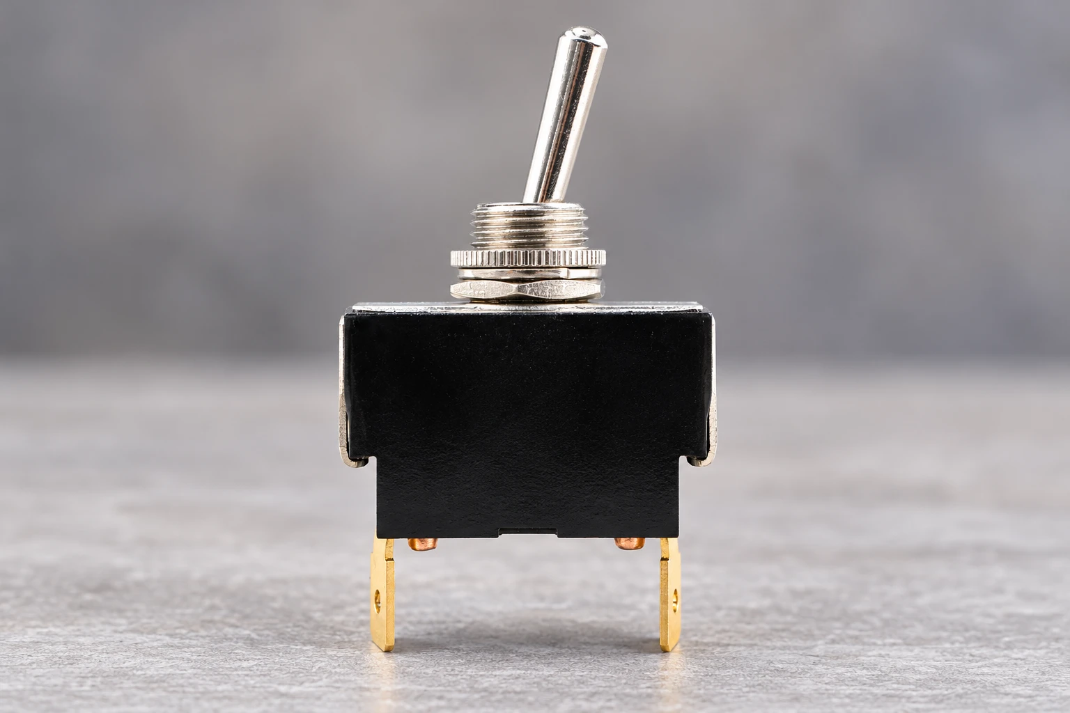
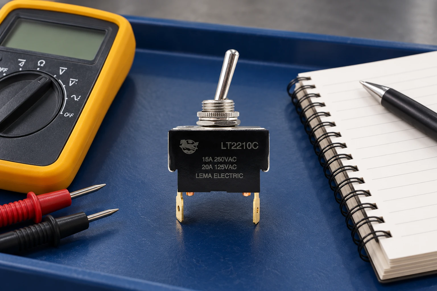
The LEMA LT2210C ON-OFF-ON 3 Position DPDT Heavy Duty Toggle Switch is the LEMA product reference illustrated here. Its photograph identifies the external product, not an unlisted rating, accessory compatibility or test result. Obtain the current specification for the full order code before approving an assembly.
Stable States Describe Positions, Not the Journey
Transition timing must therefore be treated as a separate characteristic. The relevant questions include whether the departing contact opens before the arriving contact closes, whether either contact rebounds, and whether an apparently open path remains electrically significant to the application. Position labels cannot answer these questions. Neither can a static continuity check performed only after the actuator has settled. The OEM should distinguish the switch’s contact truth table from its dynamic contact behavior throughout the qualification record.
BBM and MBB Describe Different Event Orders
Break-before-make, often abbreviated BBM, requires an open interval between the relevant departing and arriving conductive states. Make-before-break, or MBB, deliberately establishes the arriving path before releasing the departing path. The resulting overlap may be useful where continuity must be maintained, but it can be unacceptable where alternate sources, signals, or operating modes must remain separated. Neither sequence is universally better; suitability depends on what the circuit permits during transfer.
The phrase “non-shorting” is commonly associated with BBM, while “shorting” may describe MBB. Those terms still need supplier clarification because their scope can differ. A designation may apply to a particular switching element, selected terminal relationships, or a specified operating sequence. It should not automatically be extended to every pole, every direction of travel, or every available switch variant. Procurement language should identify the exact contact relationships for which the sequence is required.
| Characteristic | Break-before-make | Make-before-break | OEM implication |
|---|---|---|---|
| Intended transfer behavior | Departing path opens before arriving path closes | Arriving path closes before departing path opens | Match the sequence to the circuit’s allowed intermediate states |
| Intermediate condition | Temporary separation | Temporary overlap | Evaluate the electrical consequence, not just the label |
| Continuity during transfer | Can be interrupted | Can be maintained through overlap | Consider downstream state retention and disturbance |
| Evidence needed | Relative opening and closing events | Relative closing and opening events | Use simultaneous observations with defined decision criteria |
| Stable-state diagram | Does not establish transitional separation | Does not establish transitional overlap | Request dynamic evidence for the specified configuration |
A Center-Off Position Is Not Proof of BBM
A center-off designation describes an intended resting state in which the relevant paths are open. It does not, by itself, establish the timing relationship during movement. The actuator may pass through the central region without dwelling there, and the internal switching mechanism need not reproduce the apparent spacing of the external lever positions. A visible detent or an off legend is therefore not a substitute for a defined transitional contact sequence.
This distinction becomes especially important when a circuit relies on isolation throughout the complete transfer rather than only while the actuator rests at center. Qualification should consider movement toward center, movement away from center, and uninterrupted travel between alternate operating positions. If the switch has multiple poles, their relative behavior also matters. A center-off description does not establish synchronized release across poles or guarantee that every circuit path becomes inactive together.
Define the Circuit Requirement Before Measuring Timing
The OEM should begin with the prohibited electrical condition. Examples include simultaneous connection of incompatible sources, overlap between mutually exclusive commands, or an interruption that leaves a control input undefined. These are different requirements and may lead to different switch choices. “Must be BBM” is incomplete unless the specification explains which paths must not coexist and what counts as an electrically active path in the finished equipment.
The circuit review should also distinguish mechanical contact separation from functional isolation. Stored energy, input capacitance, leakage, suppression components, and downstream response can keep a function active after a contact opens. Conversely, a newly closed contact may not immediately establish the intended operating state. A mechanically valid BBM sequence can therefore fail to provide functional exclusivity at system level. Component qualification and circuit validation answer related but separate questions.
Specify the required response to an intermediate open condition as well. The equipment may need to retain its previous state, enter a defined inactive state, or reject ambiguous commands. Where consequences are significant, evaluate whether the architecture needs an independent means of enforcing exclusivity. A toggle switch’s nominal transition characteristic should not become an unstated substitute for a system-level protective requirement.
Use Simultaneous Capture to Establish Event Order
A meaningful timing evaluation observes the departing and arriving paths on a common time reference. A capture with separate channels for the relevant paths can reveal whether their conductive intervals are separated, overlapping, or obscured by bounce. Separate tests performed on different actuations cannot reliably establish relative timing, because each mechanical operation may differ. The essential evidence is the relationship between contact events during the same transfer.
The measurement method needs enough temporal discrimination to resolve the behavior being evaluated, without mistaking instrument artifacts for contact events. Channel alignment, acquisition behavior, trigger selection, filtering, and signal interpretation all affect the result. A display that looks clean is not necessarily conclusive. The report should explain how an open or closed condition was recognized and whether brief events could have been suppressed, averaged, or missed.
Capture review should include the full transition rather than an isolated crossing. A departing path may open, rebound into conduction, and then open again while the arriving path is already active. An initial opening event alone would suggest separation, while the complete record would reveal later overlap. Similarly, arriving-contact bounce can create intermittent conduction rather than a clean final closure. Acceptance criteria should address the complete event sequence that matters to the circuit.
Understand the Limits of Isolated Continuity Testing
Isolated continuity testing can help characterize mechanical sequencing without exposing the observation system to the application’s operating energy. It can reveal relative contact activity under the selected sensing conditions and is useful for comparing samples or investigating a disputed sequence. Its strongest conclusion is limited, however: it demonstrates what the contacts did under that test method, not everything they will do under the equipment’s actual electrical conditions.
Continuity instruments and sensing methods differ in detection thresholds, response behavior, and treatment of unstable resistance. An audible indication or slowly updated display may conceal brief opens or overlaps. Contact films may also behave differently under sensing conditions than under the intended load. A continuity result should therefore be reported with its interpretation criteria, rather than reduced to an unexplained pass indication.
Electrical isolation also changes what can be inferred about arcing, residual charge, load transfer, and other energized effects. An open mechanical contact does not automatically mean that all application current has ceased at the same instant. Where those effects are relevant, separate application-representative evaluation is necessary through appropriately controlled laboratory methods. Isolated testing remains valuable, but it should not be presented as proof of energized transfer performance.
Include Variation, Bounce, and Service Conditions
Timing evidence should reflect the conditions covered by the OEM requirement. Actuation direction, operating style, temperature, mechanical wear, and manufacturing variation can affect the observed sequence. The supplier and OEM should agree which conditions are relevant rather than assuming that a favorable trace from a fresh sample represents the complete production population. Any excluded conditions should remain visible in the qualification conclusion.
For multipole switches, evaluation may require more than the basic capture of the departing and arriving paths on a selected pole. A pair of channels can establish a particular relationship, but it cannot automatically characterize every cross-pole combination. If the circuit depends on coordinated behavior across poles, define those relationships explicitly and obtain suitable evidence. Avoid translating a per-pole BBM statement into an unsupported claim of globally exclusive circuit states.
Separate continuity checks from transfer-time evidence
Static continuity testing can help map terminal states, but it cannot establish the duration of a brief overlap or open interval. A timing assessment needs appropriate simultaneous observation of the relevant paths, a defined stimulus and a stated measurement resolution. Channel offsets and the observation threshold can affect interpretation. Use a qualified laboratory procedure rather than making live supply-transfer measurements to investigate an unknown switch.
Distinguish contact bounce, movement between stable positions and the circuit response to those events. Filtering may conceal a transition without changing what the contacts actually do. Ask the supplier for the exact variant diagram and supported transfer characteristics, including the conditions behind them. The illustrated LEMA toggle is a product-reference specimen, not evidence that its transition has been classified or approved for a supply-transfer function.
Technical references and the scope of this review
IEC 61058-1 appliance switches: The applicable switch specification and equipment requirements govern acceptance. The standard catalogue does not identify the transition behavior of the illustrated part.
HSE electrical testing at work: Use qualified testing and an isolated, controlled setup. A general continuity demonstration is not permission to test live supply-transfer circuits.
For the wider component decision, see Toggle Switch Mechanism: How It Works and How to Select One. Complementary checks are covered in ON-ON-ON Toggle Switch: Circuit Logic and Wiring and Center-Off Toggle Switch: ON-OFF-ON Circuit Uses. These pages address separate questions and do not replace the acceptance evidence defined here.
Further learning
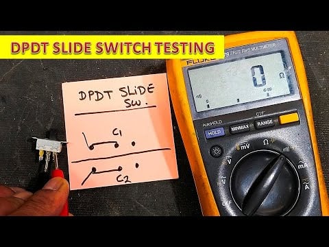
This independent demonstration shows static testing of a DPDT slide switch. It helps explain terminal-state checks; it does not classify the illustrated toggle or measure its dynamic transfer time.
Watch {923} How to test dpdt slide switch — Haseeb Electronics
Frequently asked questions
Does center-off prove break-before-make timing?
It identifies a stable position but does not by itself specify every dynamic transfer characteristic.
Can a slow continuity meter measure a brief overlap?
It can map static states but cannot establish a timing interval beyond its measurement capability.
Is the illustrated toggle approved for supply transfer?
No such approval or timing classification is claimed. Obtain exact variant documentation and equipment assessment.
Can software filtering change the contact transfer itself?
Filtering changes the observed circuit response, not the physical order in which the contacts change.