A center-off toggle switch has three stable lever positions—ON, OFF and ON—so the middle position disconnects the controlled path while either outer position selects a different circuit state. It is commonly used for forward/stop/reverse requests, raise/stop/lower controls, source selection and manual mode commands. The label describes lever behavior, not the internal terminal map. Pole count, maintained or momentary action, contact sequence, voltage, load and interlocking must all be verified before wiring.
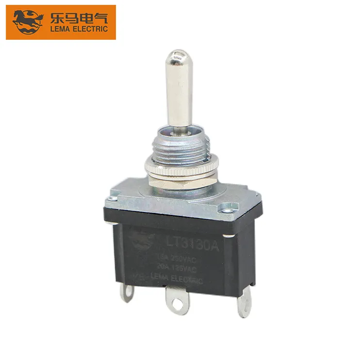
This guide explains how to specify an ON-OFF-ON switch without confusing it with ON-ON-ON or momentary variants. LEMA LT3130A images are real product references. Always use the exact model drawing and continuity table for the selected ordering code.
Center-off patterns compared
| Marking | Center state | Outer positions | Typical use |
|---|---|---|---|
| ON-OFF-ON | Maintained open/neutral state | Two maintained selections | Direction or source selection with a stop position |
| (ON)-OFF-(ON) | Maintained center | Momentary both sides | Raise/lower or jog commands |
| (ON)-OFF-ON | Maintained center | One momentary, one maintained | Mixed command functions after risk review |
| ON-ON-ON | Connected center pattern | Two additional connected patterns | Multi-circuit selection; not center-off |
| ON-OFF | No third position | One connected, one disconnected | Simple two-position control |
Parentheses conventionally indicate spring-return positions, but markings vary. Confirm the mechanical action and circuit diagram instead of ordering from punctuation alone.
What happens in the center position
In a true center-off function, the relevant moving contact is not connected to either outer throw in the center position. In a single-pole version, a common terminal usually selects one of two throws. In a double-pole version, two independent commons change together. The center may disconnect both poles, but terminal numbering and physical layout differ between families.
Center-off does not guarantee galvanic isolation for every circuit or a safety-rated stop. Contact spacing, leakage through other components, shared commons and downstream electronics still matter. If isolation or hazardous-motion stopping is required, use devices and architecture specifically approved for that function.

SPDT and DPDT terminal logic
An SPDT center-off switch normally has three functional terminals: COM, throw A and throw B. One outer position connects COM to A, center connects neither, and the other outer position connects COM to B. A DPDT version duplicates that behavior across two poles, often with six terminals. It can route two conductors or create logic that requires two synchronized contact groups.
Do not infer the commons from terminal position. With power isolated, map continuity in all three lever positions and record the result. Compare it with the manufacturer drawing. The DPST wiring guide explains why pole and throw terms must remain separate, while the ON-ON-ON guide covers the different connected-center pattern.
Forward-stop-reverse applications
A center-off switch can provide direction requests to a controller, relay pair or motor control circuit. The center position requests stop, while the outer positions request opposite directions. The switch should not be assumed to reverse a motor directly. Motor starting current, inductive interruption, dynamic braking, contactor interlocking and safe reversal delay can exceed what a panel toggle should handle.
Use electrical and mechanical interlocks where simultaneous forward and reverse outputs would be harmful. Define what happens when the lever passes through center, when power returns, and when an end limit is active. A controller input arrangement often allows clearer interlocks and diagnostics than direct power switching.
Raise-stop-lower and jog controls
For hoists, actuators and adjustment mechanisms, momentary outer positions may be preferable: the operator holds the lever toward raise or lower and it returns to center when released. That behavior is written (ON)-OFF-(ON), not simply ON-OFF-ON. A maintained model stays in an outer position and may keep commanding motion unless the controller or limits stop it.
Select action from the machine risk assessment and operating sequence. Limit switches, overload protection and controller logic remain separate safeguards. The lever style does not prove suitability for lifting people, suspended loads or safety-related motion.
Source and mode selection
Center-off can select between two signal sources, operating modes or control circuits while providing a neutral state. For low-level analog, audio or sensor signals, contact resistance, shielding, grounding and break-before-make behavior can matter more than current rating. For power circuits, creepage, clearance, short-circuit protection and load category are important.
Some circuits cannot tolerate a brief open state during transfer; others must never connect both sources together. Determine whether the contact sequence is break-before-make or another arrangement and verify it under the actual switching speed. Do not use a generic center-off switch as a transfer switch between independent mains sources without an approved transfer architecture.
Maintained versus momentary action
A maintained ON-OFF-ON switch remains where the operator places it. A momentary outer position returns to center by spring force. Mixed-action variants return from one side but latch on the other. These distinctions affect restart behavior, operator expectation and PLC programming.
Write the state table before choosing the part: lever left, center and right; contact state for every pole; command at the controller; behavior on release; behavior after power restoration. This simple document prevents a model that “has three positions” but behaves incorrectly in the machine.
Electrical rating and load type
Match the exact voltage, AC or DC duty, current, load type, switching frequency and expected life. Resistive ratings do not automatically apply to motors, solenoids, lamps or capacitive inputs. Inductive loads may require an interposing relay, contactor or suppression network. Review the 2-pin toggle-switch wiring guide for basic circuit boundaries, and do not extrapolate beyond documented ratings.
The IEC 60947-5-1 standard page identifies the control-circuit device standard family. Product compliance, utilization category and ratings must be confirmed for the exact switch and target market rather than inferred from appearance.
Panel and terminal selection
Check panel cutout, anti-rotation feature, thread length, nut arrangement, maximum panel thickness, handle clearance and access behind the panel. A boot or sealed front does not automatically seal the terminals or rear enclosure. If the panel must meet an ingress requirement, validate the complete installed assembly.
Choose solder, screw or quick-connect terminals for the production process and service environment. Specify conductor size, insulation, terminal support, strain relief and protective covers. The toggle-switch mounting-hole guide helps define the panel interface, but the exact product drawing remains controlling.
Safe verification before energizing
- Match the part number and action marking to the bill of materials.
- Identify terminals from the drawing rather than their physical order.
- With power isolated, measure continuity in left, center and right positions.
- Confirm center is open for every intended pole.
- Check momentary return or maintained detents as specified.
- Verify panel torque, anti-rotation and terminal insulation.
- Test controller interlocks and direction changes at safe reduced energy.
- Confirm power-restoration and fault behavior before production release.
The OSHA electrical safety resources provide general workplace safety context. Follow the equipment’s applicable procedures, including isolation and verification of de-energization.
OEM RFQ checklist
State ON-OFF-ON or the exact parenthesized momentary action, pole count, contact table, load and utilization, voltage, current, operating frequency, panel thickness, cutout, terminal type, sealing needs, handle style, marking, ambient conditions, required approvals and expected service life. Include the desired circuit state after power restoration and any interlocking handled elsewhere.
Compare the requirement with the LEMA LT3130A product reference and the broader toggle-switch range. Request a sample and controlled drawing for wiring and panel verification.
During sample approval, compare lever position, detent feel, continuity results, panel fit and terminal access against the production drawing. Record the tested model and revision. This prevents a visually similar two-position or momentary variant from entering production under the same informal description.
FAQ
Is ON-OFF-ON the same as ON-ON-ON?
No. ON-OFF-ON has a disconnected center state for the relevant poles. ON-ON-ON uses a connected center pattern.
Does center-off mean the motor is electrically safe?
Not automatically. Other power paths, stored energy or control faults may remain. Use the machine’s approved isolation and safety architecture.
Can an ON-OFF-ON toggle reverse a DC motor directly?
Some DPDT circuits can reverse polarity, but direct suitability depends on motor starting and stall current, DC interruption rating, protection and interlocking. A controller or relay interface is often preferable.
How do I identify the common terminals?
Use the exact diagram and a de-energized continuity test in all positions. Do not rely solely on terminal location or color.
Video: toggle-switch mechanism
This educational animation shows how a toggle mechanism transfers contacts. It supports understanding of lever and contact action but does not replace the selected model’s contact table.