An ON-ON-ON toggle switch is a three-position selector with an active contact combination in all three lever positions. In the common DPDT six-terminal version, the two poles do not necessarily transfer in the same way at the center position: one pole may connect toward one end while the other connects toward the opposite end. That staggered center logic is what makes series/split/parallel and other three-mode circuits possible. Never wire it from an ON-OFF-ON diagram; identify every continuity pair on the exact switch first.
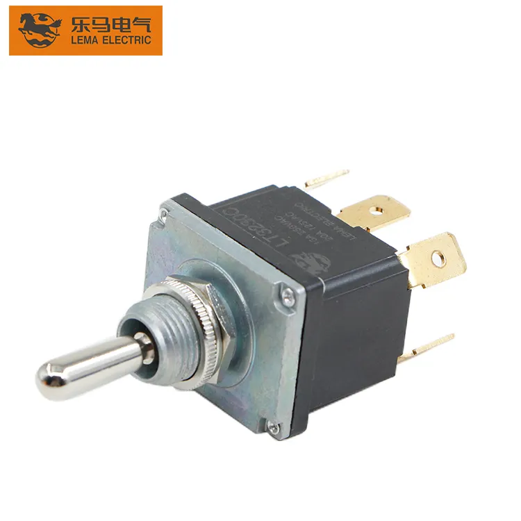
This guide explains ON-ON-ON toggle switch logic, terminal mapping, bench testing and OEM selection. LEMA product photos illustrate the physical DPDT toggle form and six-terminal layout. The referenced LT3230C listing is ON-OFF-ON, so its exterior photograph must not be treated as proof of ON-ON-ON internal contacts.
ON-ON-ON is a contact sequence, not an appearance
Three-position toggles can share the same lever, bushing and terminal footprint while having different internal sequences. ON-OFF-ON opens both poles in the center. ON-ON uses two maintained positions. Momentary functions are shown with parentheses, such as (ON)-OFF-(ON). ON-ON-ON maintains a defined connection in every position. The ordering code and contact table, not the number of detents or terminals, distinguish them.
| Marking | Lever positions | Center behavior | Do not assume |
|---|---|---|---|
| ON-ON | Two maintained | No center detent | Not a three-mode selector |
| ON-OFF-ON | Three maintained or mixed | Both poles normally open | Center is not an active route |
| ON-ON-ON | Three maintained | Staggered or defined active contacts | Center pattern is not universal |
| (ON)-OFF-(ON) | Momentary ends | Open center | Lever does not stay at the ends |
Some suppliers publish more than one ON-ON-ON center-contact pattern. A guitar-wiring source may call them Type I and Type II; industrial datasheets may use a contact truth table. Both descriptions mean the assembler must verify the exact variant. A familiar six-lug drawing from another brand is not evidence for a LEMA ordering code.
Number the terminals before drawing the circuit
Place the isolated switch on the bench in a repeatable orientation and take a photograph. Assign temporary terminal numbers from the rear view, for example left column 1–2–3 and right column 4–5–6. State explicitly whether the drawing is viewed from the terminal side or lever side. The center terminal in each column is often the common for that pole, but “often” is not sufficient for production. Find it with continuity.
Use a meter with an audible continuity function or low-ohms display. Record every closed pair with the lever in the upper, center and lower detents. Do not test through installed jumpers, loads or parallel circuits. Repeat the sequence several times and turn the switch 180 degrees only after the first table is complete; this catches the common error of mirroring a rear-view diagram.
A City Tech laboratory manual provides an independent educational reference for DPDT switch testing and wiring. Seymour Duncan’s ON-ON-ON explanation documents why more than one center-contact pattern exists. Use these to understand the method, not as the LEMA product specification.
Build a continuity truth table
A useful truth table lists the switch position down the first column and both pole connections across the row. An ON-ON-ON device may connect one common to its upper throw and the other common to its lower throw in the center. At the two end positions, the poles change according to the manufacturer’s pattern. Because patterns vary, this article does not assign universal terminal numbers to those connections.
- Isolate all six terminals and verify the meter by shorting its probes.
- At position A, test every likely common-to-throw pair and record only stable closures.
- Repeat at center and position C.
- Confirm that each pole has a defined route at all three positions.
- Compare the measured table to the manufacturer’s contact diagram and ordering code.
- Only then add circuit jumpers and wire labels.
If the center position shows no continuity on both poles, the switch is likely ON-OFF-ON rather than ON-ON-ON. If the lever springs back, the code includes a momentary function. If one reading changes with pressure on the lever, check the test fixture and contact condition rather than designing around an unstable result.
Why the middle position is useful
The staggered center permits three circuit states using only two poles. In an audio pickup circuit it can support series, single-coil and parallel modes when the pickup leads and jumpers are arranged correctly. In instrumentation it can choose three signal routes or combinations. In low-voltage controls it may select operating modes, but the control system must tolerate any make-before-break or break-before-make transition defined by the switch.
Do not assume ON-ON-ON is a general three-source selector. A DPDT device has two poles and two throws; the third lever state is created by a combination of those contacts, not a third independent throw per pole. If the application requires one common to choose one of three completely independent outputs, an appropriate multiposition rotary switch or electronic selector may be clearer.
Make-before-break, break-before-make and transition states
A static truth table does not fully describe what happens while the lever moves. Contacts may open before the next contact closes, or overlap briefly. The datasheet may specify the sequence; if it does not, treat the transition as indeterminate and ensure the circuit remains safe. This matters when switching power sources, reversing motors or feeding logic inputs that must never be active together.
For motor direction, use appropriate interlocking relays or a controller rather than relying on an undocumented manual-switch transition. For two sources, prevent backfeeding and verify that switching under load is permitted. A terminal current label does not establish safe source transfer, isolation coordination or motor utilization. These functions require a system-level design.
Rating and load checks
Select the switch for voltage, steady current, inrush, load type, duty, switching frequency and environment. AC and DC ratings are not interchangeable, and an inductive load can stress contacts differently from a resistive load. If the switch only sends a low-current command to a PLC or relay coil, confirm the minimum applicable load and any suppression device. If it directly switches a load, use the exact utilization information from the datasheet.
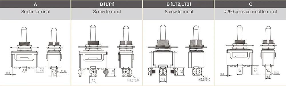
The panel design also needs bushing thread, anti-rotation feature, nut torque, cutout, rear clearance, terminal spacing, ingress protection and boot compatibility. Compare the broader LEMA toggle-switch range and the LT3230C DPDT product for physical reference, while requesting a genuine ON-ON-ON ordering code and truth table if that is the required function.
Wiring workflow for an OEM harness
- Freeze the full switch part number and revision.
- Attach the verified three-position truth table to the electrical drawing.
- Define terminal numbering and drawing viewpoint.
- Show every external jumper individually; do not hide it behind a generic switch symbol.
- Assign wire numbers and insulation ratings based on the circuit.
- Build one first article, then continuity-test it from the harness connector.
- Energize with current limitation and verify all three functional states.
- Check transient behavior and fault response before approving production.
The DPDT OEM selection guide explains the basic two-pole matrix. The three-position toggle guide covers the wider family, including sequences that differ from ON-ON-ON. For terminal hardware, see the quick-connect terminal guide. Keeping these decisions separate prevents a diagram from being applied to the wrong part.
Troubleshooting unexpected modes
If the two end positions work but the center does nothing, confirm whether an ON-OFF-ON part was supplied. If center works but selects the wrong combination, the diagram may use the other ON-ON-ON pattern or be mirrored. If only one pole changes, check the common identification and the crimp on the second pole. If a mode changes when the lever is touched, inspect terminal strain, mounting alignment and contact stability.
Do not move wires randomly until the desired result appears. Update the continuity truth table after every part substitution. Purchasing should treat the contact sequence as a controlled characteristic, because a visually identical alternative can produce a hazardous or simply incorrect center state.
RFQ checklist
Send the required ON-ON-ON truth table, number of poles, maintained positions, transition requirement, circuit voltage and current, load type, terminal style, panel thickness and cutout, sealing need, operating temperature, cycle expectation and destination approvals. Ask the supplier to return a model-specific drawing showing the terminal view and contact sequence. A request that says only “six-pin three-way toggle” is ambiguous.
FAQ
Is ON-ON-ON the same as ON-OFF-ON?
No. ON-ON-ON has an active connection combination in the center. ON-OFF-ON normally opens both poles in the center.
Can I identify ON-ON-ON by six terminals?
No. Six terminals indicate a likely DPDT format, but ON-ON, ON-OFF-ON, momentary and ON-ON-ON versions can share it. Test continuity and check the part code.
Are all ON-ON-ON center patterns identical?
No. More than one staggered-contact pattern exists. Use the exact manufacturer truth table or map the isolated switch with a meter.
Can an ON-ON-ON toggle reverse a motor directly?
Do not assume so. Motor reversal requires verified contact sequencing, load ratings, transient protection and interlocking. A relay or motor controller is often the appropriate interface.
Video: testing a DPDT contact matrix
This independent demonstration shows how to map a six-terminal DPDT switch with a multimeter. Apply the method to all three detents of the exact ON-ON-ON part.