
DPDT hardware is a two-pole assignment problem, not a thicker SPDT. Write what each pole switches, then request samples. Unused contacts still confuse harness teams when the drawing stays silent.
Important: Do not treat DPDT as a flexible upgrade label for any multi-screw toggle. Confirm both poles against selected-model documentation before panel release. Source note: IEC 61058-1 publication scope and selected-model documentation.
– FAQs
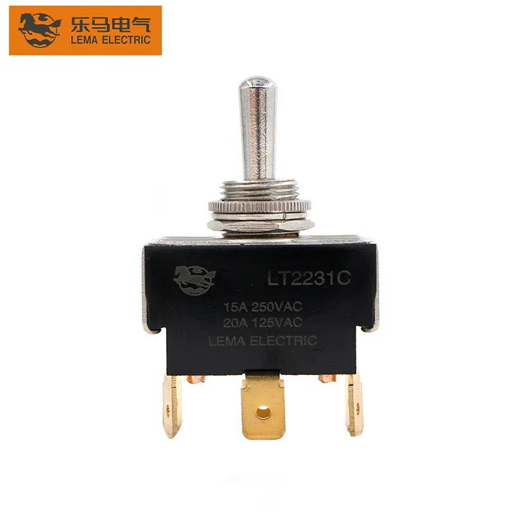
Part 1. When does a panel truly need DPDT instead of SPDT?
Choose DPDT when two circuits must change state together—or when isolation between poles is required by the schematic. A single SPDT cannot honestly carry two independent loads.
| Decision field | Input to document | Send with quote |
|---|---|---|
| Pole map | Load on pole A and pole B | Yes — dual-path schematic |
| Circuit form | Maintained states per pole | Yes — printed form |
| Isolation need | Why poles must stay separate | Yes — design note |
| Panel fit | Cutout and clearance | Yes — mounting drawing |
Index families from the LEMA Toggle Switch product line after the pole map exists.
Part 2. How should both poles be documented on one schematic?
Draw both commons and their throws on one sheet. Shared lever motion does not excuse missing contact labels; each pole needs a pin map the harness can follow.
If the team is still identifying a single-pole common, finish the SPDT terminal identification work first rather than jumping to DPDT by habit.
Part 3. Which maintained states still must be printed on the BOM?
BOM lines must carry the printed circuit form, not only “DPDT.” Maintained ON-OFF versus ON-OFF-ON still changes operator behavior even when poles are doubled.
Logic framing remains useful in the ON-OFF versus ON-OFF-ON logic article before the dual-pole package is frozen.
Part 4. How do cutout and clearance checks change with dual poles?
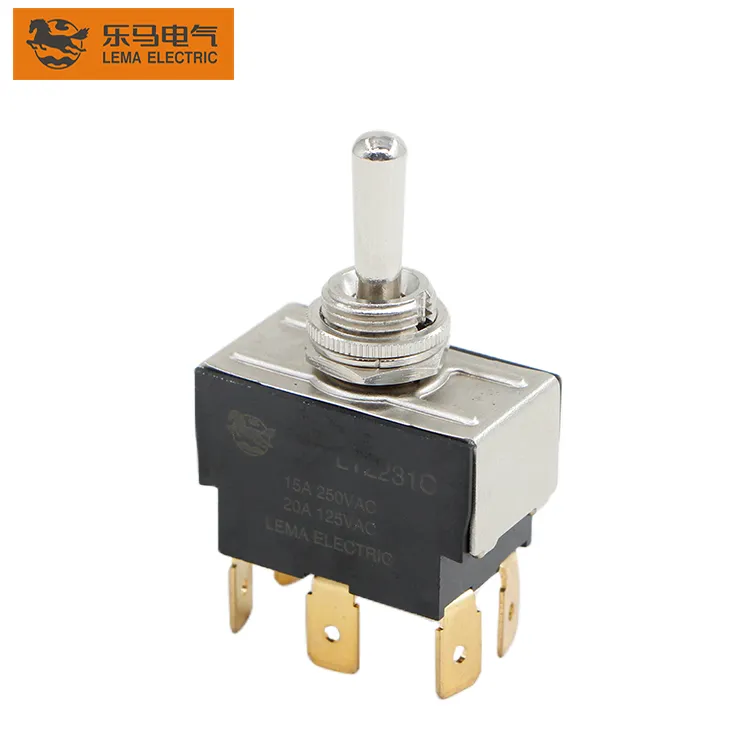
Six-terminal bodies and longer levers often need more rear and swing clearance than compact SPDT parts. Capture hole size, panel thickness, locknut stack, and adjacent legend clearance on one drawing.
- Confirm bushing thread against the model drawing.
- Reserve space for full lever travel.
- Note terminal bend radius behind the panel.
- Higher continuous loads may also need the heavy-duty rating review.
Part 5. How should load notes stay tied to each pole?
Record voltage, steady current, and inrush per pole when duties differ. A single amp number that ignores which pole is live is not enough for contact review.
| Note | Strong version | Weak version |
|---|---|---|
| Load | Current per pole with inrush | One unlabeled amp figure |
| Terminals | Style mapped to both poles | Terminal TBD |
Part 6. How should dual-circuit panels be validated before release?
Validate both poles on a production-intent panel, confirm labels match harness pins, and prove the operator script cannot leave an unintended live path on either circuit.
Fit Boundary: this guide plans DPDT dual-circuit OEM selection. It does not certify ratings, prove sealing, or establish a safety function.
Part 7. How can LEMA support a DPDT panel inquiry?
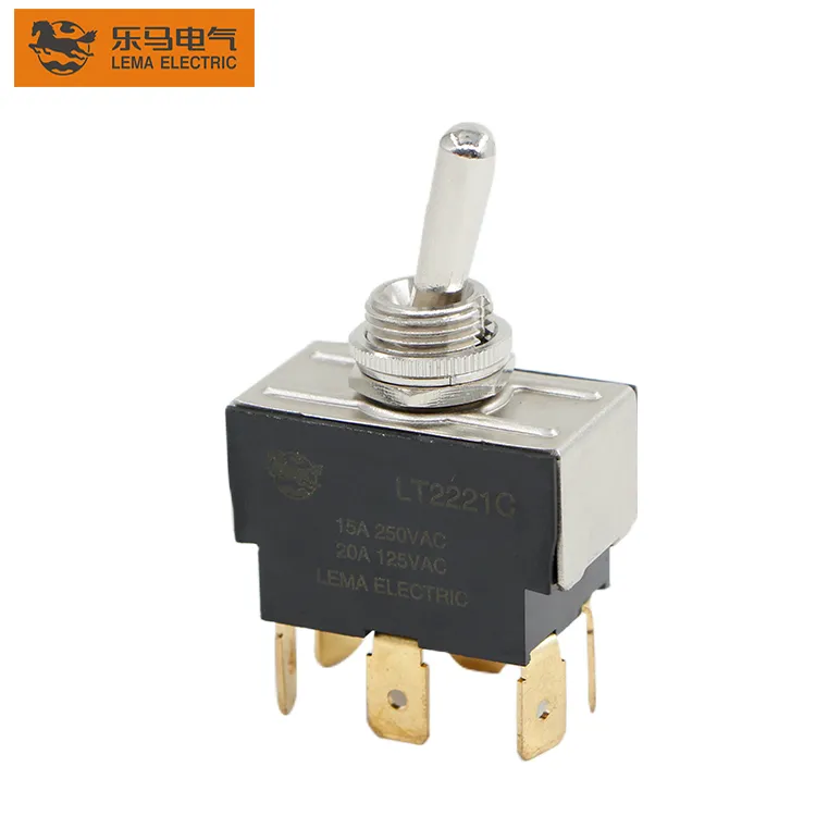
Use the LT1 series toggle switch page once the pole map and mounting envelope are complete. Sealed fronts can move to the LT3 series waterproof toggle switch route after exposure is defined.
Send with the inquiry:
- DPDT pole map with load per pole
- Printed circuit form and safe-state note
- Cutout, panel thickness, and clearance
- Terminal plan, volume, and sample timing
Product recommendation: request a documented LEMA review against the dual-circuit drawing. Do not approve a “six-pin toggle” nickname alone.
Send a toggle-switch RFQ with the drawing package attached.
## FAQs
What is a DPDT toggle switch used for?
It switches two poles with one lever, suiting dual-circuit panels that must change two paths together or keep them isolated.
Is DPDT the same as two SPDT switches?
Mechanically linked poles differ from two separate SPDT devices; document the required linkage and isolation explicitly.
Does DPDT always reverse a motor?
No. Motor reversing is one pattern; many OEM panels use DPDT for unrelated dual loads.
Can I leave one DPDT pole unused?
Only with a written reason; unused contacts still need labels so service teams do not invent wiring.
How does DPDT relate to ON-OFF-ON?
Poles and throws are separate from maintained-state logic; print both on the schematic.
What belongs in a DPDT toggle RFQ?
Include the pole map, circuit form, load per pole, cutout, terminals, environment, volume, and sample timing.
## References