CENTRO NOTIZIE LEMA

News e Blog

Centro Notizie

Limit Switch Head Types and Adjustable Actuator Positions
Blog LEMA Electric

Limit Switch Head Types and Adjustable Actuator Positions

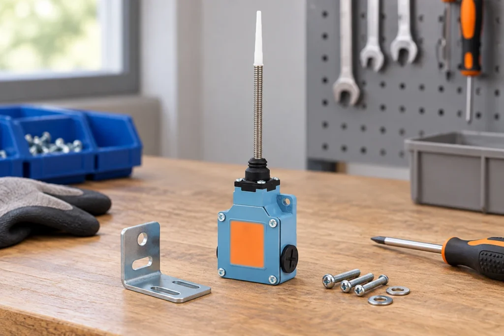
Limit switch heads should be chosen for the target motion, permitted approach direction and operating travel of the exact switch family. Roller levers, plungers, rods and other actuator forms are not interchangeable simply because they detect position. Some constructions allow a head to be repositioned under a defined procedure; others do not. Confirm the complete head and body combination, orientation options and instructions before changing an installed switch.This guide focuses on head selection and orientation for mechanical position switches. It complements the broad actuator-types and mounting guides, rather than giving universal instructions for rotating any head. LEMA LZ1 switch images are the real product reference; their external appearance does not prove field interchangeability with another series. Separate the head from the complete switch identity A position switch assembly includes the body, contact arrangement, head, actuator and mounting. A replacement head must match the relevant family and approved combination. Similar screw patterns or housing shapes do not prove that the internal operating relationship, sealing or travel is correct. Order and inspect the complete identified construction.Record the body and head codes where the maker provides them. If the head is not offered separately or no approved interchange information exists, do not assume it is a service part. Ask for the complete switch option instead. This avoids substituting a physically attachable head that changes the electrical or mechanical operation without an established acceptance basis. Describe the target approach in three dimensions Identify where the moving target contacts the actuator and how it approaches, passes and leaves. A roller lever can suit a cam profile, while a plunger may suit a controlled pressing direction. A rod or flexible actuator may detect movement over a...

Leggi di più
Antirimbalzo degli interruttori a pulsante per gli ingressi di PLC e microcontrollori
Blog LEMA Electric

Antirimbalzo degli interruttori a pulsante per gli ingressi di PLC e microcontrollori

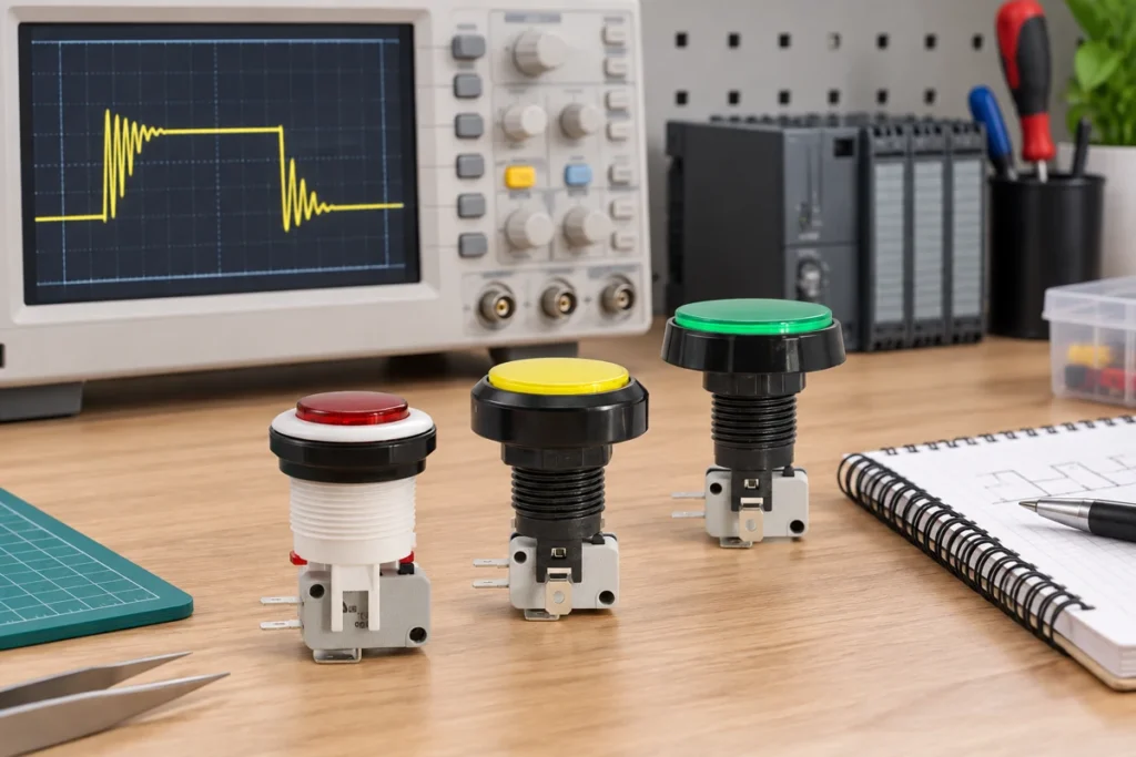
Push button debounce makes one intended operator action produce the intended controller event despite brief contact transitions. For ordinary PLC or microcontroller command inputs, first establish the raw electrical state, then accept a stable state and generate the required press or release event. Choose filtering from measured contact behavior and the acceptable response time; do not apply one fixed delay to every button or use filtering to hide defective wiring.This guide concerns normal operator commands such as selecting a mode or counting presses. It does not design an emergency-stop or other safety function. LEMA PBS push buttons are the illustration reference. The exact contact arrangement, action and controller input requirements still need confirmation for the chosen model. Define the command before choosing a filter Write down what one press is supposed to do. It may toggle a mode, increment a value, issue a single start request or hold a manual command while pressed. Those functions require different event logic even when the physical button is identical. Identify whether press, release or both transitions matter and whether a held button should repeat.Create acceptance examples before implementation: one press gives one event; holding gives the specified behavior; a rapid second press is accepted or intentionally rejected according to the requirement. Also define startup behavior when the button is already held. A filter can produce a stable state but still create the wrong command if the event rules are incomplete. Distinguish contact bounce from other signal problems Moving contacts can settle through several transitions around one actuation. The University of Washington Makeability Lab lesson explains this basic contact-bounce mechanism. A trace that continues changing while the button is held can have another cause,...

Leggi di più
Heavy-Duty Limit Switch Selection: A Field Checklist for Industrial OEMs
Blog LEMA Electric

Heavy-Duty Limit Switch Selection: A Field Checklist for Industrial OEMs

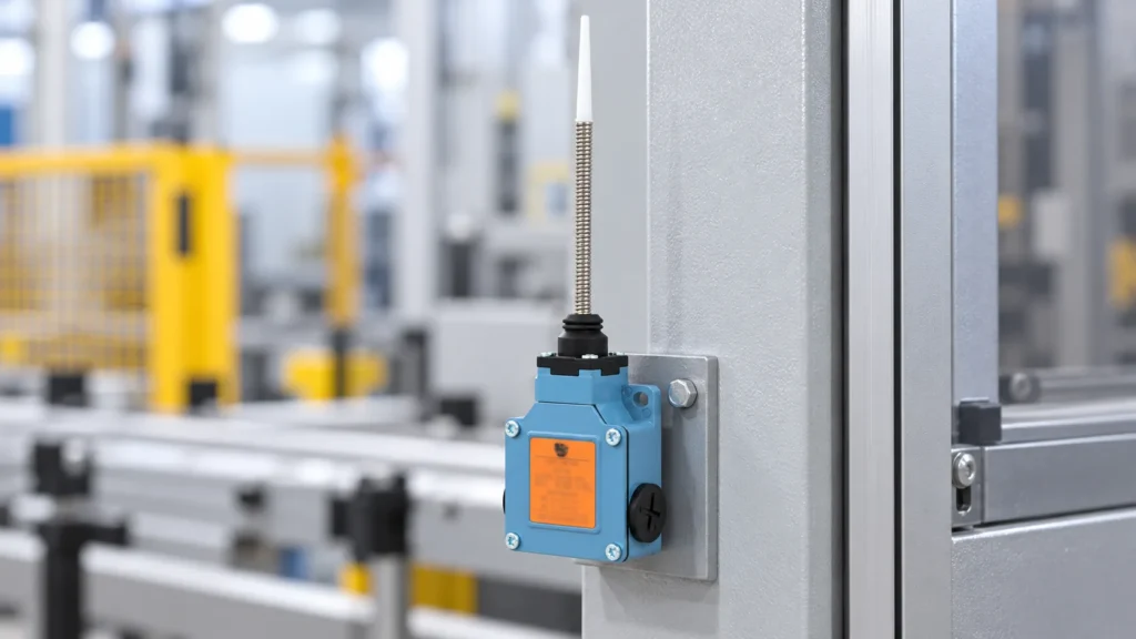
Product-based illustration generated from the LZ1 product photograph. The mounting scene is illustrative; confirm the exact model, actuator and installation conditions against its drawing. A heavy-duty limit switch should be selected by the loads and environment it must survive—not by the adjective on a catalog page. Start with the machine motion and the required switching point, then match an actuator, mounting position, enclosure protection, contact duty and service plan to that application. Ask for model-specific ratings and test evidence; “heavy duty” is not a universal certification or a substitute for an equipment risk assessment. LEMA’s LZ1 Series page, for example, lists an aluminum-alloy limit switch with an IP66 enclosure rating and separate AC-15 and DC-13 contact ratings. Those claims apply to the stated series information and must still be checked against the exact order code and machine design. Define what “heavy duty” must withstand Write down the stresses before comparing part numbers. A press, conveyor, hydraulic cylinder, outdoor mechanism and washdown machine can all be described as demanding, but they do not impose the same stresses. One may need a robust actuator and repeatable switching position; another may need a sealed enclosure, a corrosion-resistant mounting arrangement or a long cable-flex life. Treat each requirement separately instead of assuming that one rating covers every condition. Build a short use profile: expected operating cycles, target approach speed, likely impact or side load, vibration, dust, liquid, cleaning chemistry, ambient temperature, cable movement and access for maintenance. Identify the consequence of a missed or false transition. If the switch is part of a safety-related control function, specify the required safety architecture and validated components separately; a general-purpose limit switch by itself does not establish...

Leggi di più
Selezione di microinterruttori antipolvere per apparecchiature industriali
Blog LEMA Electric

Selezione di microinterruttori antipolvere per apparecchiature industriali

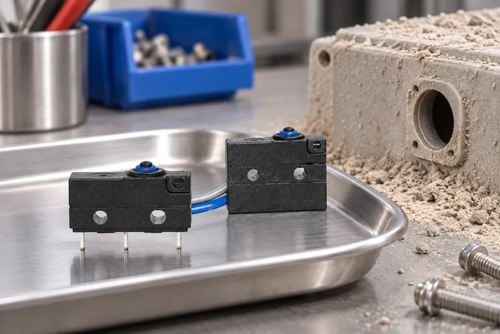
A dustproof micro switch must be selected from documented ingress protection and the actual installation boundary, not a sealed-looking housing or a general waterproof label. Identify the dust exposure, actuator movement, cable or terminal entry paths and surrounding enclosure. Then confirm the exact switch variant's evidence and validate its function in the intended mechanism. A switch body can resist ingress while dust still obstructs the external roller, lever or target.This guide focuses on industrial position and mechanism inputs. It excludes mouse-click sound comparisons and does not claim that every LEMA waterproof micro switch has a particular dust classification. The KW12F wired switch family is the real product reference; request the applicable construction and test information for the order code being considered. Describe the dust before choosing the switch Record what generates the dust and where it reaches the mechanism. Dry process powder, fibers, wood residue and abrasive particles create different practical problems. Include particle accumulation, airflow, cleaning methods and whether liquid or oil makes the dust adhere. A simple label such as dusty workshop does not give the supplier enough information to evaluate the application.Identify the function and consequence of a missed or unstable input. A production-position indication and a safety-related interlock can need different system architecture and validation. Do not elevate a general micro switch to a safety device because it is sealed. The equipment design authority must establish the required function and approved control arrangement. Read the ingress classification correctly IEC 60529 provides the IP classification framework for enclosure protection. For a switch, ask for the full relevant classification and conditions tied to the exact construction. Do not infer dust performance solely from a water-related description. A statement...

Leggi di più
How to Choose a Micro Switch Lever Length
Blog LEMA Electric

How to Choose a Micro Switch Lever Length

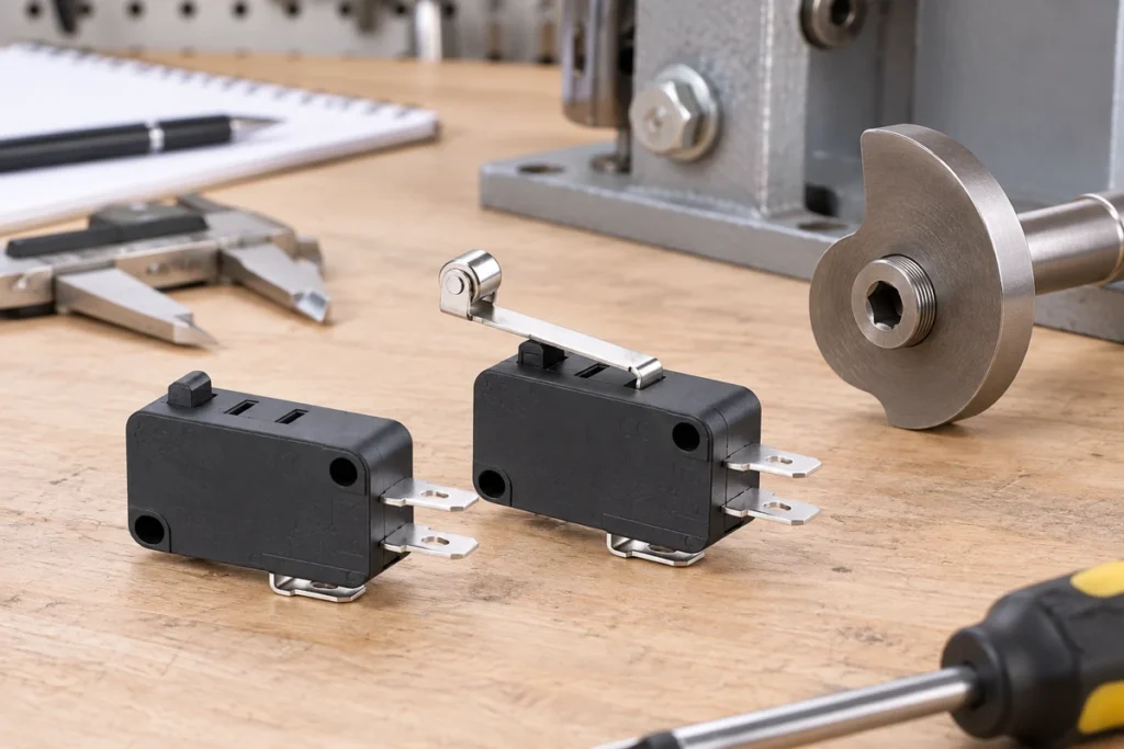
Micro switch lever length should be chosen from the mechanism's motion, contact point, required operating force and permitted travel. A longer lever can change mechanical advantage, but it also changes displacement and the moving envelope. Measure from the relevant pivot or reference defined in the switch drawing, not merely the exposed metal strip. Select a complete actuator variant and verify operation and release in the real mechanism rather than bending a stock lever until it seems to work.This guide focuses on choosing lever geometry for repeatable OEM position detection. It complements the broader actuator-types and force-selection guides. LEMA KW7 roller-lever micro switches are the product reference; the illustrations are not dimensioned drawings or permission to modify the actuator. Define what the mechanism needs to detect Start with the target event: a part reaches a position, a cam rotates through a point, a door closes or an item passes a sensing station. Record both the required operating state and the release state. Decide whether the controller needs a held condition, a pulse or a change of state. Lever selection must support that function across the expected movement.Identify the available motion at the intended switch location. Include approach direction, displacement, speed and how accurately the target is guided. A lever that reaches a distant target may solve packaging but introduce sensitivity to lateral motion. Where the target location is uncertain, compare a different mounting position before assuming that a longer lever is the best correction. Read the actuator-specific drawing Obtain the full switch order code and drawing for the actual lever or roller option. Identify the pivot, permitted contact region, operating position, release behavior and maximum allowed travel. A body-family drawing without...

Leggi di più
Selezione delle rondelle di tenuta e degli O-ring per interruttori a levetta
Blog LEMA Electric

Selezione delle rondelle di tenuta e degli O-ring per interruttori a levetta

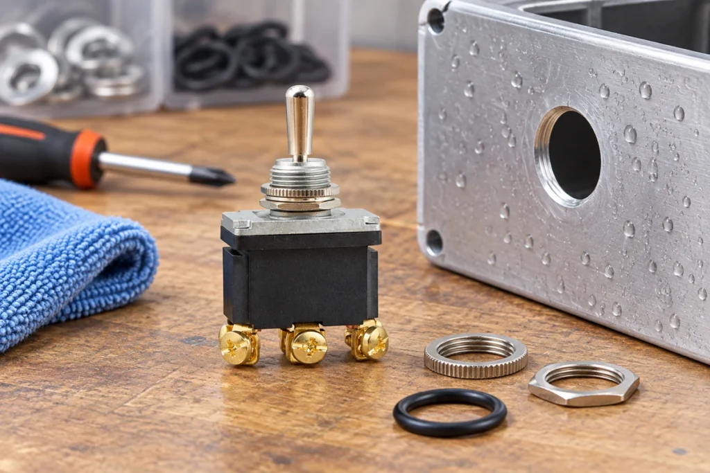
A toggle switch sealing washer closes a specific path at the panel interface when its material, geometry and compression match the approved switch assembly. It is different from a lock washer, an anti-rotation washer and a lever boot. Select the seal using the switch bushing drawing, finished panel, exposure conditions and maker's assembly instructions. Adding an arbitrary O-ring or tightening the nut harder does not establish waterproof performance.This guide focuses on the seal around a panel-mounted toggle bushing. It complements whole-switch environmental selection and boot selection. The LEMA LT3232B waterproof-toggle family is the product reference; its photograph does not establish that any aftermarket washer produces a particular IP rating. Map every relevant entry path Identify where moisture or dust could move into the enclosure: around the bushing, through the lever mechanism, along a threaded accessory or through rear connections. A panel washer addresses only the interface it is designed to seal. Even a correctly installed washer cannot make an unrelated opening watertight or protect exposed rear wiring.Review the complete assembly instead of the accessory in isolation. Record the switch model, panel, nut, seal and any boot together. Ask which combination was evaluated for the claimed environment and how it was mounted during that evaluation. This prevents a component-level claim from being applied automatically to the finished equipment. Distinguish sealing from locking and anti-rotation A lock washer is intended to help the fastener arrangement resist loosening. An anti-rotation washer or keyed feature limits body rotation. A sealing washer creates the specified barrier at the panel interface. These functions can be combined in an approved assembly, but one should not be assumed to replace another.Use the stack order in the supplier instructions....

Leggi di più
Power Socket Terminal Types: Solder, Quick Connect and PCB
Blog LEMA Electric

Power Socket Terminal Types: Solder, Quick Connect and PCB

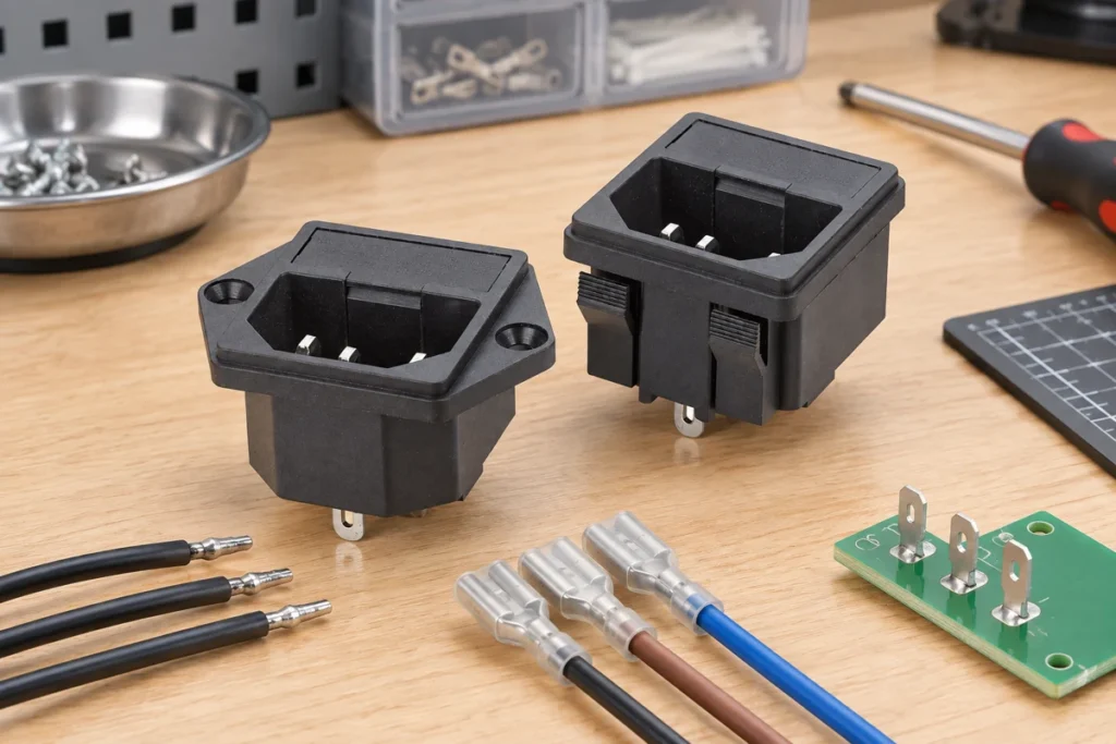
Power socket terminal types determine how an equipment inlet connects to its internal circuit. Solder lugs need a controlled soldering process and supported wires; quick-connect tabs need compatible receptacles and documented crimps; PCB pins need an exact footprint and a board design suitable for the circuit. The connection style is separate from the inlet's mating designation, current rating and protective-earth arrangement. Select the complete inlet variant and termination system together.This guide concerns equipment power inlets, including LEMA IPZ products. It does not describe household outlet installation or assume that every IPZ variant offers every terminal option. Confirm available constructions, electrical identity and mounting details from the specific model drawing before ordering or connecting a part. Start with circuit identity and the rear view Identify the equipment circuit and the inlet terminals from its actual marking and drawing. A rear view can reverse the apparent left and right relationship compared with the mating face. Never identify line, neutral or protective earth solely from a familiar photograph. Record viewing direction on the wiring drawing and check it against the approved sample.Where the circuit includes a fuse, switch or filter, establish the connection paths for that exact module. A similar housing can contain a different arrangement. Keep terminal function separate from terminal shape. Use qualified personnel and a safely isolated assembly for inspection; a connection guide cannot replace the equipment's electrical design, approved procedure or applicable safety evaluation. Specify solder lugs as a production process Obtain the permitted wire size, attachment method and soldering exposure from the component maker. Define the soldering equipment, materials, process window and inspection criteria. Do not let operators compensate for an unsuitable connection by applying progressively more heat...

Leggi di più
Subminiature vs Miniature Micro Switch: Size and Load Comparison
Blog LEMA Electric

Subminiature vs Miniature Micro Switch: Size and Load Comparison

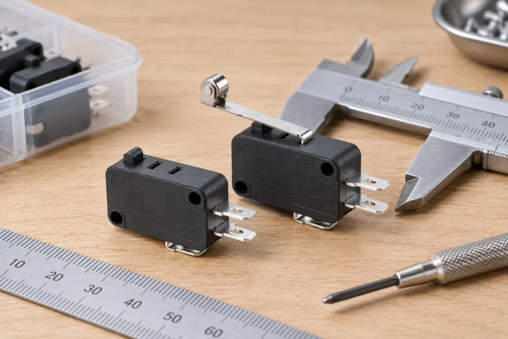
Subminiature versus miniature micro switch selection is a comparison of complete candidate parts, not a rule that the smaller name means lower current or shorter life. Suppliers use size categories to organize families, while the housing drawing, actuator envelope, contact duty and mounting arrangement determine whether a switch fits a mechanism. Choose the smallest candidate that meets the actual force, travel, connection and electrical requirements with a validated assembly margin.This guide compares design tradeoffs rather than repeating a catalog of compact switches. LEMA KW7 micro switches provide the illustration reference. The pictured parts are not a calibrated size comparison and do not establish that every family has a particular current, life or temperature rating. Compare occupied envelopes instead of body length alone Measure the space needed by the housing, actuator through its full permitted movement, terminals, mating connectors and mounting hardware. A shorter body can need a longer harness bend or an awkward bracket. A nominally larger housing can sometimes make the complete assembly easier to package because its connection or actuation direction suits the machine.Draw the released and operated positions of each candidate. Include moving parts nearby and the space needed for a tool during assembly. Check clearance after tolerances are applied. The useful comparison is the occupied and serviced envelope in the mechanism, not the area covered by a catalog photograph. Keep the measurements tied to the exact order code and drawing revision. Treat size names as family labels Miniature, subminiature and ultra-miniature are convenient descriptions, but a buyer should not use the words as a replacement specification. Ask for actual dimensions and mounting details. Two switches carrying similar labels can have different holes, pin spacing, actuators and...

Leggi di più
Guida al ritaglio del pannello e al montaggio dell’ingresso di alimentazione IEC
Blog LEMA Electric

Guida al ritaglio del pannello e al montaggio dell’ingresso di alimentazione IEC

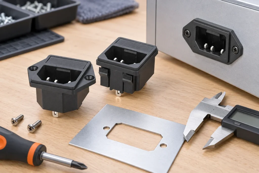
IEC inlet cutout dimensions must come from the exact inlet mounting drawing, including its tolerances, corner radii, panel thickness and flange or clip arrangement. The C14, C20 or other mating designation does not supply a universal equipment-panel opening. Two appliance inlets that accept the same cord connector can need different cutouts. Before releasing a panel for production, compare the complete order code, current drawing and finished enclosure sample.This guide focuses on converting a supplier drawing into an inspectable enclosure feature. It does not publish guessed dimensions or a generic template to print and trace. LEMA IPZ inlet images illustrate the product category; use the specific variant's drawing to establish all actual dimensions. Identify the interface being dimensioned An inlet has several different interfaces: the mating connector face, the body passing through the panel, the flange or retaining clips, and the rear terminals. Identify which one each drawing view describes. A mating-interface dimension must not be substituted for the body opening, and a flange dimension must not be used as the cutout width.The IEC appliance coupler standard sheets concern coupler dimensions and gauges. They are useful for identifying the connector framework, but the supplier's mounting drawing remains necessary. Confirm whether a view is from the mating face, the rear or a section through the panel. Mark the reference direction on the enclosure drawing so the shop does not mirror asymmetric features. Obtain the complete variant and revision Use a drawing tied to the full order code. A product family may offer different terminal styles, mounting flanges, snap features or integrated functions. Those options can change rear clearance or the panel interface. A photograph of the family is therefore insufficient to release...

Leggi di più
Micro Switch Terminal Types: Solder, PCB and Quick Connect
Blog LEMA Electric

Micro Switch Terminal Types: Solder, PCB and Quick Connect

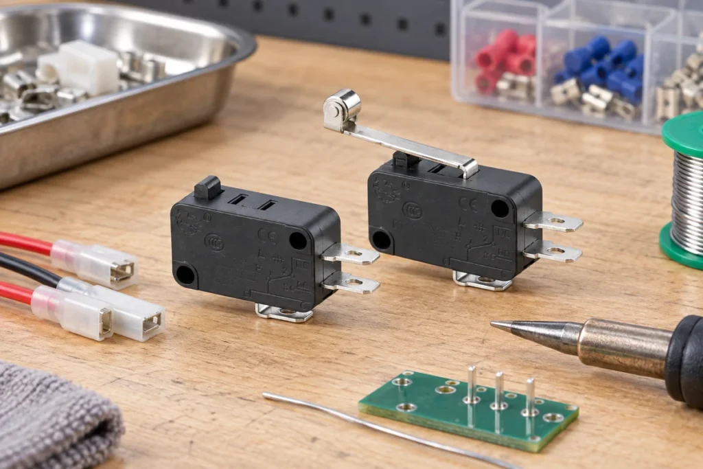
Micro switch terminal types should be selected around the assembly process and circuit duty. Solder terminals suit a controlled wire-soldering process, PCB pins suit a verified board footprint and mechanical support, and quick-connect tabs suit an approved mating receptacle and harness. The terminal style does not identify common, normally open or normally closed contacts, and it does not by itself establish current capacity. Choose the complete switch variant, mating parts and termination method together.This guide addresses connection design for OEM mechanisms using snap-action micro switches. It complements contact identification and multimeter testing rather than replacing them. The LEMA KW7 family provides a real product reference for the photographs; confirm the exact terminal variant on the order drawing before specifying a production connection. Separate terminal form from contact function A three-terminal snap-action switch often provides common, normally open and normally closed contacts, but those functions must be established from the specific diagram. A blade, solder lug or PCB pin can serve any of the contact functions. Do not assign function from terminal length, location or a photograph of another model.Create two records: a physical terminal drawing and an electrical state table. The first identifies dimensions, spacing, orientation and permitted connection technique. The second records continuity at released and operated positions. Keep both with the harness documentation. When the production variant changes, verify both records rather than assuming that a familiar housing means the same pin arrangement. Solder lugs require heat and strain control A solder lug gives a wire a defined attachment point, sometimes with an opening that supports positioning. Confirm whether the maker permits wire wrapping, the specified soldering temperature and duration, and the wire size compatible with the terminal....

Leggi di più
Ingresso di alimentazione IEC a incastro o con fissaggio a vite
Blog LEMA Electric

Ingresso di alimentazione IEC a incastro o con fissaggio a vite

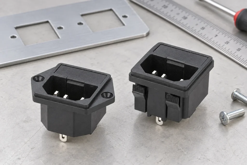
Snap-in versus screw-mount power inlet selection starts with the enclosure, not the connector name. A snap-in inlet relies on its specified retaining features engaging a panel within an approved thickness and cutout range. A screw-mount inlet uses a flange and compatible fasteners to secure the body. Either approach can work when the actual inlet drawing, finished panel, wiring space and service method agree. Neither approach is automatically stronger, more waterproof or electrically safer merely because of its mounting style.This guide concerns equipment appliance inlets, such as the LEMA IPZ product family. It does not compare household receptacle push-in wire connections. Keep mechanical retention separate from the terminal connection method: a snap-in body can still use solder or quick-connect terminals, and a screw-mounted body can use several terminal arrangements. Compare retention paths rather than marketing labels Sketch the path followed by a force when a user inserts or removes the mating cord connector. It travels through the inlet body, retaining clips or flange, and finally the enclosure panel. A retention problem anywhere in that path can allow movement even if the electrical connection remains continuous. Evaluate pull, push and sideways loading separately; a housing that resists straight extraction may still rock in an oversized hole.For snap-in mounting, identify which surfaces grip the rear of the panel and which stop against the front. For screw mounting, identify the flange bearing surface, screw engagement and any backing feature. Record these details on the assembly drawing so the shop can inspect the real load path, instead of judging the installation by how firmly the part seems to click. Panel thickness includes coatings and local features The usable panel thickness is the finished thickness at...

Leggi di più
Woodworking Foot Switch Selection for Equipment OEMs
Blog LEMA Electric

Woodworking Foot Switch Selection for Equipment OEMs

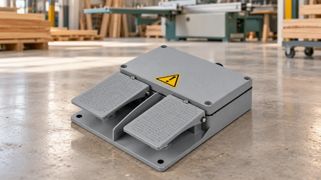
Generated from the original LF-series dual-pedal product image. It is an illustrative product example, not a machine-specific safety approval. A woodworking foot switch lets an operator control equipment without moving a hand from the work area, but that convenience does not make the pedal a safeguard. Machine builders should first decide whether the pedal is a momentary command, a maintained on/off control or part of a multi-step sequence. Then match the contact duty, mounting, cable, floor conditions and dust exposure to the machine. A pedal that looks sturdy may still have the wrong electrical rating, return action or guard geometry. For a woodworking foot switch, validate the pedal and its controller as part of the machine design, and keep blade guarding, stop functions and lockout procedures separate. Define what the pedal is supposed to do Start with the machine sequence, not the switch catalogue. A foot pedal might request a temporary run command, enable a cycle while it is held, move a powered table, or select one of several machine functions. These actions require different control behavior. A momentary foot switch returns to its rest state when released. A maintained switch changes state and remains there until it is pressed again. A dual-pedal assembly may command two directions, separate actions or a sequence managed by the machine controller. Write down what should happen on press, release, power loss, cable failure and restoration of power. If releasing the pedal must stop motion, the controller and power switching path must be designed and validated to produce that behavior. Do not infer a “dead-man” or safety function from the pedal’s shape, color or return spring. RequirementTypical design questionWhat to verify Momentary run requestMust...

Leggi di più