
Micro switch roller wear should be inspected as a problem at the complete target interface, not judged from a noisy input alone. Examine the roller, its support, the lever, the cam surface and their relative movement. Record the original condition before cleaning or adjusting anything. A worn target, a loose bracket or an unsuitable approach can produce symptoms that resemble a worn switch roller, and fitting another switch without correcting that cause may repeat the problem.
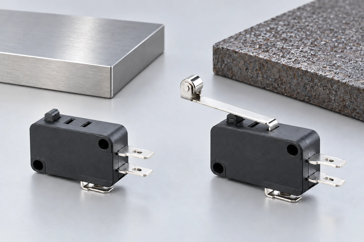
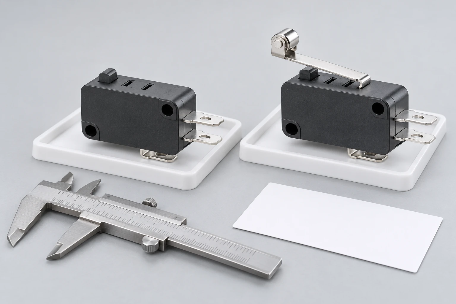
The LEMA KW7 product family includes the roller-lever form used in these illustrations. The pictured specimens are intact reference products; they are not evidence of a failed unit or a claim about a universal wear limit. Obtain the drawing and permitted operating conditions for the exact actuator variant.
Define the symptom before naming the worn part
Describe what the equipment actually did. Examples include a changing trigger position, a rough mechanical feel, an intermittent input or a target that no longer clears the lever. Record when the symptom occurs and whether it follows a particular direction, speed or portion of the machine cycle.
Do not diagnose roller wear solely from an electrical trace. Contact behavior, wiring, input filtering and target movement can produce similar reports. Compare the mechanical observation with the isolated electrical state and the controller indication. The micro switch failure-mode guide provides the wider fault-boundary framework; this article focuses on the roller and the surface that drives it.
Keep the original adjustment intact until it is documented. An immediate position change can make the machine run again while hiding the evidence needed to understand the wear process.
Isolate the mechanism and preserve the original condition
Follow the equipment’s energy-control procedure before inspecting the roller or target. Account for stored motion and other energy sources, not only the electrical control supply. Do not rely on the switch being investigated to prevent movement while a hand or instrument is near the cam.
Photograph the actuator, target, mounting and surrounding clearances from useful angles. Include identification markings and any relevant loose material. Record cleaning, lubrication or adjustments already performed. A specimen that has been scrubbed or bent cannot be interpreted as though its original condition was preserved.
The HSE electrical-testing guidance provides safety context for controlled investigations. It does not replace the machine procedure or authorize an improvised live test near a moving target.
Inspect the roller surface and movement
Look for visible damage, an uneven running surface, contamination, a changed shape or evidence that the roller is not moving as intended. Use suitable lighting and magnification, and distinguish a surface mark from a dimensionally significant change. Do not scrape or polish the surface merely to improve its appearance.
Check the roller support and the lever as separate features. A roller can appear intact while its support is loose or the lever is distorted. Conversely, a surface deposit may affect the interface without proving that the underlying roller material has worn away.
Use the manufacturer’s inspection method and limits where available. This article does not prescribe a permissible flat, diameter loss or amount of play. If the acceptance criterion is missing, document the observation and obtain model-specific guidance rather than creating an arbitrary replacement threshold.
Inspect the target with equal care
Examine the surface that contacts the roller through the complete approach, dwell and exit. Look for burrs, sharp edges, roughness, steps, loose fasteners and local damage. A small defect on the target can repeatedly load the same part of the actuator.
Confirm that the target remains secure and follows its intended path. Runout, backlash, vibration or bracket movement can alter the contact conditions even when the nominal drawing is unchanged. Record whether the abnormal contact occurs only at one machine position or after a change in direction.
The cam-profile design guide addresses the geometry of approach and departure. A roller is not permission to accept arbitrary impact, scraping or side loading. Evaluate the actual relative motion against the component’s approved conditions.
Compare the working position and return clearance
Wear can change the effective relationship between the target and actuator. Check whether the assembly still provides its required operated margin and released clearance without exceeding allowed travel. Do not simply move the switch closer until the input changes again.
Record the mounting references and measurement points. If dimensions are compared, use consistent units and a repeatable datum; the NIST guidance on SI length provides the measurement-unit basis. A photograph without a defined reference cannot establish a small dimensional change reliably.
Include the lever and support in this review. A change in roller contact position can change the effective lever geometry. The lever-length guide provides the separate actuator-geometry context. Preserve the reference point and variant identity when comparing the interface before and after a suspected change.
Distinguish adjustment drift from material wear
A changing trigger point does not necessarily mean that a running surface has lost material. Compare fastener seating, witness marks, bracket stiffness and the target location. Determine whether the whole assembly moved before attributing a shift to the roller itself.
The mounting and repeatability guide explains why stable references matter. Although it addresses limit-switch assemblies more broadly, the same inspection discipline helps separate a moving support from a changing actuator surface.
Preserve individual observations across cycles. An average trigger position can conceal intermittent mechanical movement or occasional failure to release. The investigation should identify the specific part of the motion in which the behavior changes.
| Observation | Separate this possibility | Useful record |
|---|---|---|
| Changing trigger position | Mounting drift rather than roller wear | Reference dimensions and fastener condition |
| Rough movement | Damaged or contaminated target | Full approach and exit surface inspection |
| Visible roller damage | Condition and support of actuator | Original photographs and exact variant |
| Fault repeats after replacement | Uncorrected target or support problem | Before and after interface comparison |
| Input instability without visible wear | Electrical or control-system boundary | Mechanical position and isolated signal evidence |
Review the exposure history
Collect the actual duty, target movement and environmental record. Note a new cam, a higher operating rate, a relocated bracket, an altered cleaning process or material accumulating at the interface. Those changes can explain why a previously acceptable assembly began to behave differently.
Do not infer a universal wear life from a catalogue mechanical-life number. The stated test conditions and the actual target interface must be compared. An unloaded mechanism test does not automatically reproduce a dirty, abrasive or misaligned machine contact.
Where the application requires exposure or endurance testing, define the specimens, conditions and acceptance criteria before starting. Include the target as well as the switch so a successful bench result does not omit the feature believed to cause the wear.
Decide whether to replace, investigate or correct the target
A visibly damaged actuator or an assembly outside its approved conditions needs the appropriate engineering and maintenance response. Do not restore it by bending the lever, tightening an unknown roller support or adding lubricant without manufacturer approval.
If replacement is proposed, preserve the removed part and compare the exact actuator variant, mounting, force and travel. The micro switch replacement guide provides the form-and-function checks. Correct a damaged target or unstable support before treating a replacement switch as the final corrective action.
For an unexplained repeated failure, send the supplier the specimen and interface evidence rather than only a close photograph of the roller. The cause may lie in how the machine applies load.
Build a repeatable release record
Record the accepted switch and target revisions, inspection findings, measured references and the final setting. Verify the complete approach, dwell, exit and return under the approved commissioning procedure. Include the conditions that originally produced the symptom where they can be reproduced safely.
Define the service inspection points that matter to this interface. A useful record names what to look at, how to identify an unacceptable condition and what action to take; it does not merely say “check switch regularly.”
Send the actual actuator and target information through the LEMA inquiry page. A documented interface makes it possible to discuss the correct roller option and evidence without pretending that every wear symptom has the same cause.
Further learning: observing mechanical movement
nptelhrd: Module 14 – Lecture 1 – Vibration Measurement. NPTEL explains observation of mechanical motion. Use it as background for relating a moving target to a signal event; it is not a roller-wear acceptance test or a KW7 lifetime claim.

Watch Module 14 – Lecture 1 – Vibration Measurement.
Frequently asked questions
Does a changing trigger point prove roller wear?
No. A moving bracket, changed target position, damaged surface or electrical-input issue can produce a similar report. Record the original references and compare mechanical movement with the actual contact and controller states before diagnosing wear.
How much roller wear is acceptable?
Use the exact manufacturer criteria and equipment requirements. This guide supplies no universal diameter loss, flat size or support-play limit. If the criterion is missing, preserve the observation and obtain model-specific guidance before accepting the part.
Should I lubricate a rough roller?
Only follow an approved method for the exact actuator. Unspecified lubricant can alter the interface or contaminate the component. Record the original condition and investigate the target, support and permitted motion before attempting a correction.
Is replacing the switch enough?
Only when the cause and the corrected assembly are established. A damaged target or unstable support can repeat the problem with another switch. Preserve the removed specimen and validate the complete approach, dwell, exit and release.