
IEC connector retention is the resistance of a mated equipment connector to unintended separation under the specified conditions. It is different from the force that holds an inlet in a panel and from the strain relief that holds a cable in its connector body. Check those boundaries separately. A connector that is hard to insert is not automatically safe, correctly matched or electrically sound, and a locking accessory cannot be assumed to fit a standard inlet without model-specific evidence.
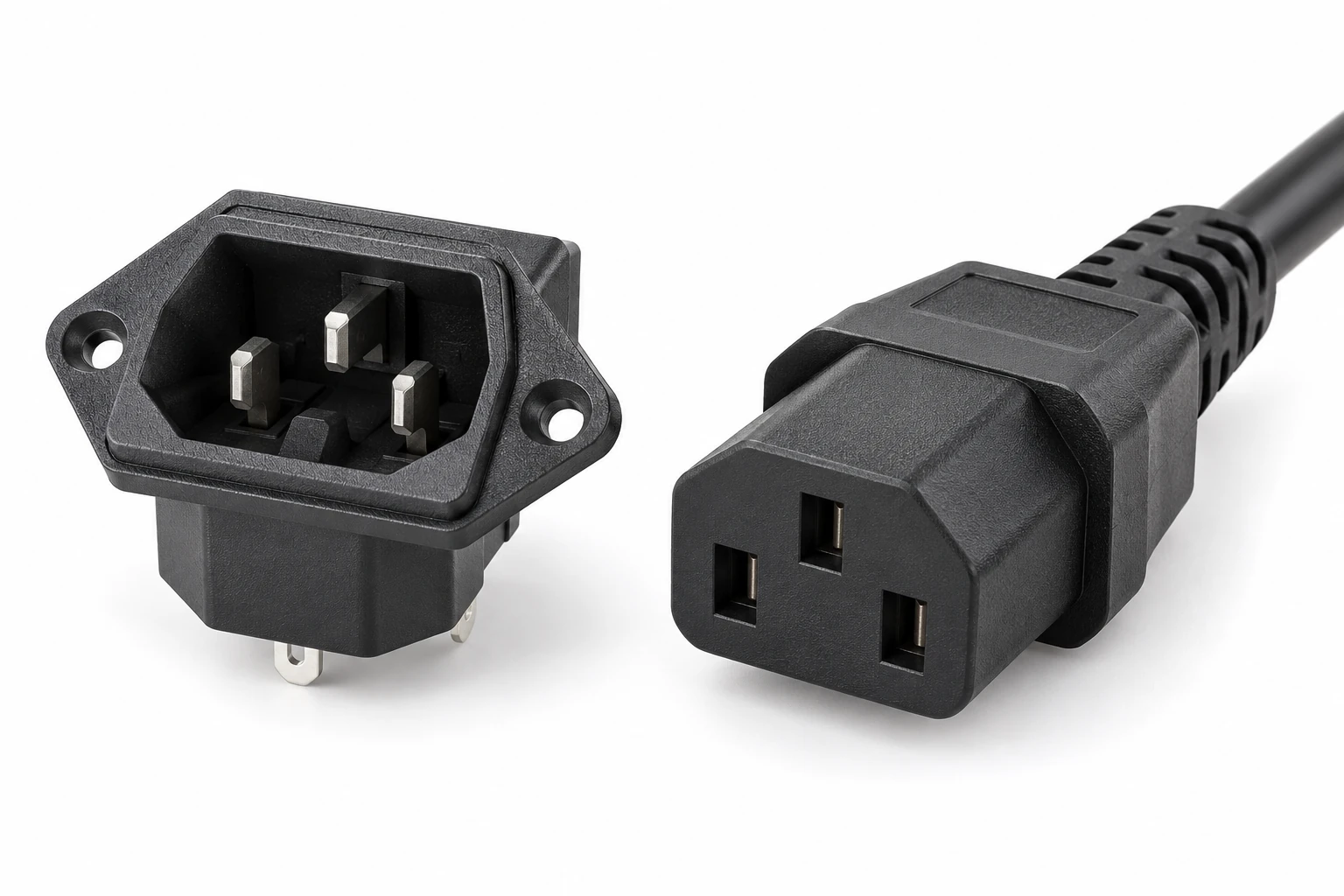
This guide uses the LEMA IPZ equipment-inlet family as a visible product reference. It does not assign a retention-force value to the family, certify a mating cable assembly or illustrate an unverified locking mechanism. Obtain the exact inlet, connector and equipment requirements before defining an acceptance test.
Identify the three mechanical boundaries
First, the mating connector has to engage the equipment inlet in the intended way. Second, the inlet has to remain securely mounted in the panel. Third, the cable has to remain properly retained within its own connector or assembly. A failure at any one boundary can look like a “loose power socket” to an operator.
Record which parts move during the reported event. Does the cable connector withdraw while the inlet stays still, does the inlet move in the panel, or does the cable move relative to its connector housing? Preserve that distinction in the inspection record. Increasing panel clamp force cannot repair a worn mating interface, and stronger cable strain relief cannot establish correct connector compatibility.
Confirm the exact mating combination
Identify the inlet and connector by their complete designations, ratings and approved cable assembly. Similar-looking parts can differ in temperature class, current rating, geometry or intended use. The C13 and C14 comparison provides background, but the actual markings and controlled specifications govern the assembly.
Do not approve a combination solely because the connector can be pushed into the inlet. Inspect for damage, distortion, contamination and evidence of forced engagement. An incompatible or damaged part can feel unusually tight without providing a suitable electrical connection.
The IEC 60320-1 catalogue entry identifies the general appliance-coupler standard. Confirm the applicable edition and product evidence for the proposed combination. The catalogue title alone does not supply a universal force limit for every inlet and connector.
Separate insertion effort from retention evidence
Insertion and withdrawal are different actions. Their measurement conditions may include specific specimens, preparation, direction, speed and conditioning. A subjective hand impression cannot be substituted for a defined test result.
If the equipment specification requires a force measurement, obtain the correct method and acceptance limits. Identify the fixture, force instrument, alignment and movement sequence. Record the actual mating parts and their condition. Do not publish a force value copied from a different connector family or a retailer’s description.
A connector may also change after repeated mating, contamination or exposure. Whether and how those conditions are included depends on the applicable test plan. A single measurement on a fresh sample does not establish the full service-life behavior of the equipment connection.
Keep cable loads away from the mating interface
Observe the real cable route. A heavy suspended cord, a sharp turn immediately after the connector or a cable caught by nearby equipment can apply a continuous load to the inlet connection. Record the direction of that load as well as its approximate source.
Plan the equipment’s cable support without obstructing access, ventilation or service. A connector should not be used as a general cable anchor. Likewise, an operator should not need to wedge a cord against an enclosure edge to prevent it from withdrawing.
The support arrangement needs to preserve the intended bend and movement conditions of the cable assembly. Do not add a tight tie around an unknown location or modify the connector body. Review the cable manufacturer’s requirements and the equipment installation instructions.
Distinguish a loose fit from an electrical overheating problem
A reported loose connection deserves inspection for both mechanical movement and electrical damage. Look for discoloration, deformation, damaged insulation, contamination and signs of abnormal heating under a safe procedure. Do not continue using a suspect connection merely because a retention accessory can keep it attached.
The power-socket failure-mode guide addresses the broader fault investigation. A high-resistance contact, an overloaded assembly and an unintended cable pull require different corrections, even when they occur at the same location.
The HSE electrical-safety questions provide safety context for removing defective equipment from service and arranging competent inspection. This article does not instruct an operator to measure contact temperature or manipulate a mains connection while energized.
Review inlet-to-panel retention independently
Inspect the panel cutout, material, thickness and the inlet’s mounting features. A snap-in body and a screw-mounted flange have different retention arrangements. Confirm the exact model drawing and approved installation rather than assuming that a similar front opening establishes the same mounting requirements.
The inlet cutout guide addresses this boundary. A connector that stays mated can still pull an incorrectly installed inlet out of the panel. Conversely, a rigidly mounted inlet does not prove that the cable connector will remain engaged under the intended service conditions.
Record the complete force path in the equipment review. Where a test loads one boundary, define how the other parts are supported. Otherwise, an apparent mating-retention result may actually describe a moving panel or an inadequately restrained fixture.
| Boundary | Movement to observe | Evidence required |
|---|---|---|
| Connector to inlet | Mating connector withdraws from fixed inlet | Exact mating specification and applicable test |
| Inlet to panel | Inlet body moves relative to enclosure | Cutout thickness and mounting acceptance |
| Cable to connector | Cable moves within its own termination | Cable assembly and strain-relief requirements |
| External cable route | Cable weight or snag loads connection | Equipment support and permitted movement |
| Accessory retention | Clip or lock changes engagement and release | Exact approved accessory compatibility |
Treat locks and retainers as specific accessories
A locking clip, cord retainer or proprietary connector system needs evidence for the exact mating combination. Do not assume compatibility from an accessory photograph. Check geometry, installation, access, release method and the effect on service procedures.
A retainer also changes how the equipment is handled. The user must be able to identify and operate the intended release without pulling the cable or damaging the inlet. Confirm that the arrangement does not defeat an equipment requirement for disconnection or create another hazard.
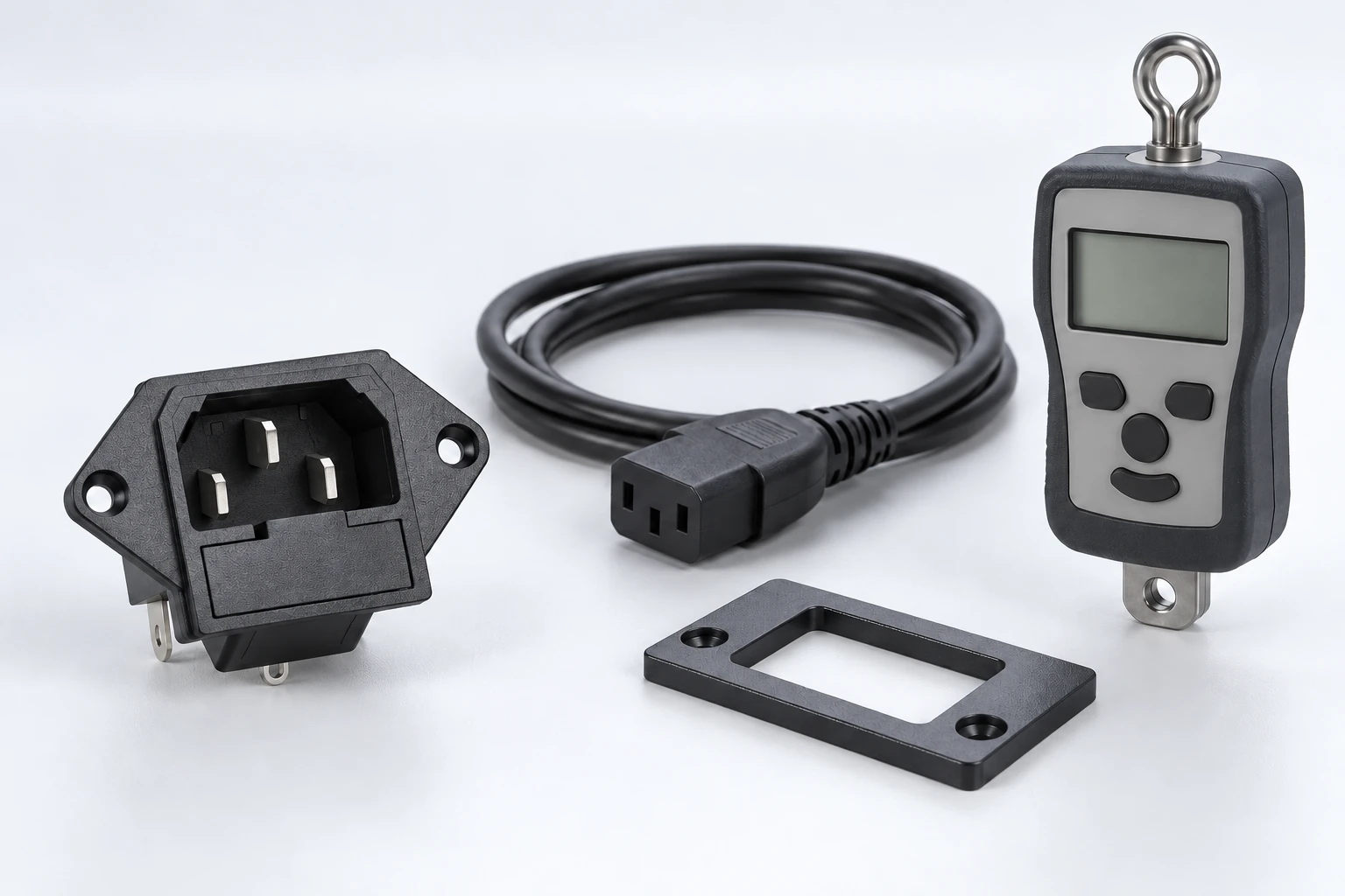
The IPZ illustrations in this article show an ordinary inlet and a separate connector only. They do not claim a locking version exists or imply that a generic clip has been approved. Ask for the supported accessory documentation if the equipment requires positive retention.
Define a controlled inspection and test plan
Begin with safe isolation and identification of all parts. Record markings, condition, mounting and cable route. Inspect the mating surfaces and panel installation before any functional test. Follow the equipment’s energy-control procedure rather than using the connection under investigation as the only means of isolation.
For an agreed mechanical test, state the load direction, fixture, instrument range, movement and acceptance criteria. Keep the test separate from electrical operation unless a competent laboratory procedure explicitly requires a combined investigation. The HSE electrical-testing guidance explains the need to control test arrangements and access.
Record individual results and any observed movement at the three boundaries. A pass or fail without that information may not explain what the assembly actually did. Photograph the supported configuration so later tests can reproduce it.
Make purchasing and service decisions traceable
Provide the complete inlet and connector models, cable assembly specification, panel drawing, installation method, operating environment and the load scenario that caused concern. Include the observed boundary of movement and any damage. Do not describe every problem as a request for a tighter socket.
If replacement is proposed, compare the mating and mounting interfaces as well as ratings and approvals. The equipment-inlet replacement guide provides a separate form-and-function checklist. Recheck the cable route and support after replacement so the original external load does not remain.
For a model-specific discussion, send the assembly evidence through the LEMA contact page. A useful retention requirement states what must remain connected, under which conditions and by which verified method.
Further learning: mechanical load and deformation
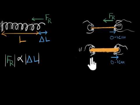
Khan Academy India – English: Stress & strain | Class 11 (India) | Physics | Khan Academy. Khan Academy explains mechanical stress and strain. It supplies general background for how applied load affects parts, not an IEC withdrawal-force method, rating or approval of the illustrated connector pair.
Watch Stress & strain | Class 11 (India) | Physics | Khan Academy.
Frequently asked questions
Does a tight-feeling connector prove correct compatibility?
No. Damage, distortion or an incorrect combination can also increase insertion effort. Identify the exact parts and inspect their condition before evaluating retention with the applicable specification and controlled method.
Is inlet panel retention the same as connector retention?
No. One holds the inlet body in the enclosure, while the other concerns the mating cable connector. Cable strain relief is a third boundary. Record where movement occurs so the correction addresses the actual problem.
Can a generic locking clip fix a loose connection?
Do not assume compatibility or use a retainer to conceal damage. Confirm the exact accessory and mating combination, installation and release requirements. Inspect any electrical damage and cable loading as separate issues.
What withdrawal force should every IEC connector meet?
The applicable value and method depend on the exact connector system, requirements and test conditions. Obtain those documents rather than copying a number from a different family or a subjective hand test.