
IEC inlet cutout dimensions must come from the exact inlet mounting drawing, including its tolerances, corner radii, panel thickness and flange or clip arrangement. The C14, C20 or other mating designation does not supply a universal equipment-panel opening. Two appliance inlets that accept the same cord connector can need different cutouts. Before releasing a panel for production, compare the complete order code, current drawing and finished enclosure sample.
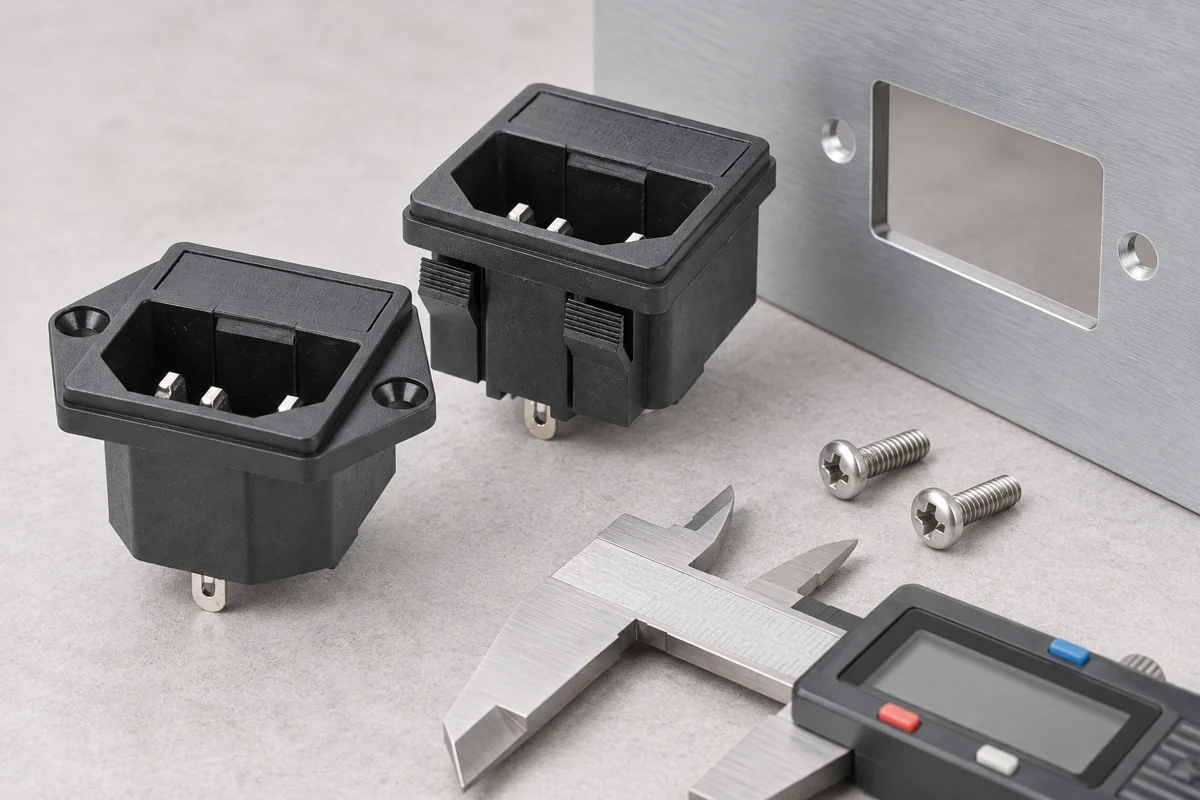
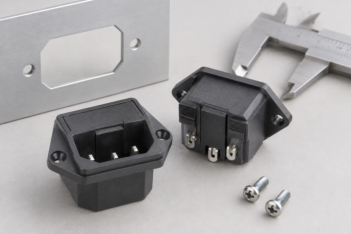
This guide focuses on converting a supplier drawing into an inspectable enclosure feature. It does not publish guessed dimensions or a generic template to print and trace. LEMA IPZ inlet images illustrate the product category; use the specific variant’s drawing to establish all actual dimensions.
Identify the interface being dimensioned
An inlet has several different interfaces: the mating connector face, the body passing through the panel, the flange or retaining clips, and the rear terminals. Identify which one each drawing view describes. A mating-interface dimension must not be substituted for the body opening, and a flange dimension must not be used as the cutout width.
The IEC appliance coupler standard sheets concern coupler dimensions and gauges. They are useful for identifying the connector framework, but the supplier’s mounting drawing remains necessary. Confirm whether a view is from the mating face, the rear or a section through the panel. Mark the reference direction on the enclosure drawing so the shop does not mirror asymmetric features.
Obtain the complete variant and revision
Use a drawing tied to the full order code. A product family may offer different terminal styles, mounting flanges, snap features or integrated functions. Those options can change rear clearance or the panel interface. A photograph of the family is therefore insufficient to release a production hole pattern.
Record the drawing revision and the source of the drawing in the part approval file. If a supplier sends a revised diagram, compare it to the current enclosure feature before ordering another batch. Ask whether the revision affects fit, acceptance gauges or assembly instructions. A document change should not silently replace the dimensions in a shop sketch without a review of existing stock and tooling.
Define the finished panel condition
Panel fit depends on the condition after cutting, forming and finishing. Include substrate thickness, surface coating, local embossing and whether the panel is flat at the flange. Check the actual contact region rather than an unrelated flat area elsewhere on the enclosure. A coating at the cut edge can reduce clearance even when the uncoated opening met the nominal size.
Establish whether cutout measurements are taken before or after finishing. If the supplier requirement is for the finished opening, the process must account for the finish. Do not compensate by enlarging every dimension without checking flange overlap and clip engagement. Validate a finished sample from the intended production process, not only a bare sheet coupon.
Control width, height and corner radii together
A housing can interfere at a corner even when width and height are within range. Specify the corner treatment shown on the approved drawing and verify that the manufacturing process can produce it. Laser cutting, milling and punching can leave different edge conditions. The selected process should meet the geometry and finish requirements without forcing the inlet into place.
Identify the dimensions used to locate screw holes, keys or retaining slots. Give the drawing a clear datum system so hole positions are not interpreted from an arbitrary outer edge. If the body outline and screw centers are independently dimensioned, check their relationship. A flange that sits crooked may be caused by a locating error rather than the inlet body.
| Feature | Evidence needed | What can go wrong |
|---|---|---|
| Opening width and height | Model-specific limits | Interference or excessive movement |
| Corner geometry | Approved radius or profile | Body catches despite correct overall size |
| Panel thickness | Finished thickness interval | Snap features do not engage correctly |
| Flange or screw holes | Locating dimensions and support | Poor seating or distorted mount |
| Rear envelope | Terminals, connectors and bend space | Harness interferes with cover or adjacent parts |
Understand tolerance limits without inventing values
Obtain the permitted dimensional limits from the inlet maker. If the drawing shows only nominal dimensions and no relevant tolerance information, request clarification before tooling. Do not treat a neat fit on one sample as proof of a reliable production interval. Both inlet dimensions and panel dimensions vary, and the combination determines insertion and retention.
For a simple clearance dimension, compare the largest relevant body envelope with the smallest permitted opening. Then check the opposite condition for retention or flange overlap. This is a design screening method, not a substitute for the supplier’s criteria. Different corners, clips and flanges may interact in ways a single width calculation does not capture. Record unresolved conditions rather than inventing an allowable gap.
Keep burrs and edge damage out of the fit test
Inspect the cut edge for sharp projections, distortions and loose debris. An inlet forced past a burr can suffer housing damage or retain metal fragments near the wiring. A snap clip may also fail to recover if the edge obstructs it. Establish a controlled edge-finishing process and inspect the resulting geometry again.
Do not grind the inlet body to compensate for a defective panel. Such rework can change insulation, retention and flange contact. If an opening rejects a correctly ordered part, compare both against their drawings. Separate a manufacturing defect from an incorrect design dimension before deciding which component requires correction. Preserve the failed sample so the cause can be examined.
Include rear wiring and connector handling space
The panel cutout is only one part of the installation envelope. Add the housing depth, terminal projection, mating receptacle length, wire bend space and safe service access to the enclosure layout. A hole can be correct while the assembled inlet remains unusable because a rear connector collides with another component.
Model the harness in its connected state and check the enclosure after covers and brackets are installed. NASA’s wiring workmanship framework is relevant background for supported connections, not an equipment approval. The actual design should prevent the enclosure from loading the terminals when the cover closes. Also provide room for the approved connector removal method so service work does not damage the inlet.
Validate retention on production-representative coupons
Make a sample panel or coupon using the intended material, cutting process and finish. Fit the correct inlet and verify seating before electrical connection. Check whether all retaining features engage or the flange bears as intended. The sample should represent the relevant dimensional extremes when the design authority requires that review.
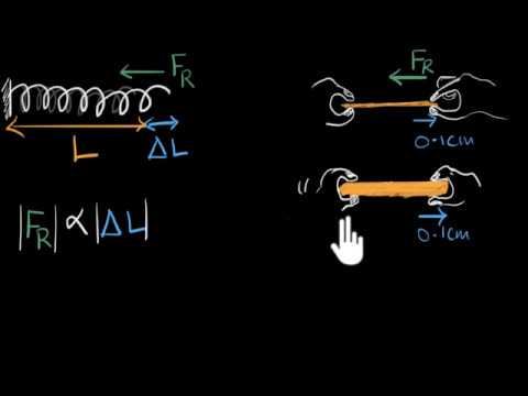
Document insertion, removal and handling checks with an approved method. Avoid describing a random push or pull as a certified retention test. If the panel flexes or the body rocks, identify the load path and the part of the interface that moves. The Khan Academy stress-and-strain video helps explain deformation generally; it does not provide inlet-specific limits.
Build an inspection method the shop can repeat
Translate the drawing into measurable checks. A caliper may suit an accessible width, but a rounded opening or hidden retention feature may require a different gauge. Define instrument choice, measurement locations and acceptance boundaries. Ensure the inspection method can distinguish a reject from an acceptable part near the limit.
Keep visual checks for flange seating separate from dimensional checks. An installed part can conceal an incorrect hole size. Sample the finished opening at the appropriate stage and verify the assembled interface afterward. Record whether the inspection applies to every panel or a controlled sampling plan. The quality authority should select the plan based on the process and consequence of a defective opening.
Manage substitutions and communicate with the supplier
For a replacement inlet, compare the entire interface instead of only the connector designation. Verify body envelope, panel thickness interval, flange dimensions, clip geometry, locating features, screw arrangement and terminal clearance. A substitute may require a new panel drawing even if the same cord connector mates correctly.
Send LEMA the full order code, panel drawing and finish details when discussing an IPZ variant. Ask for confirmation of the proposed cutout and mounting conditions. Provide photographs that show the installed interface and rear wiring region. Keep the approved drawing and sample acceptance record with the purchasing specification so future buyers can order the same construction rather than a visually similar product.
Further learning
The lesson introduces deformation under load. It supports the discussion of panel flex and retaining-feature behavior; use model-specific drawings and acceptance tests for the installed inlet.
Related LEMA resources
- IEC Power Inlet Panel Cutout and Mounting Guide product reference
- Equipment inlet selection
- Snap-in and screw-mount retention
- Power entry module architecture
Technical references
- IEC appliance coupler dimensions: Defines appliance coupler standard sheets; request the exact supplier mounting drawing for the enclosure cutout.
- NASA wiring workmanship standard: A reference for controlled cable and harness workmanship; it does not certify the illustrated LEMA part.
Frequently asked questions
Is every C14 inlet cutout identical?
No. The mating connector type and the enclosure mounting interface are different. Obtain the exact inlet drawing and compare body, flange, retaining features and panel thickness requirements before releasing a cutout.
Can I scale a product photograph to obtain dimensions?
No. Perspective, cropping and image resizing make that unreliable. Use a supplier drawing with dimensions, tolerances and revision information. A physical sample helps confirm the drawing but should not replace it.
Should I measure before or after powder coating?
Measure at the stage required by the approved mounting specification. If fit is defined on the finished panel, account for coating and verify the finished opening. Keep the measurement stage explicit in shop instructions.
What if the inlet fits but moves slightly?
Compare the body, cutout, panel thickness and retention arrangement with the approved requirements. Do not automatically add foam or adhesive. Identify whether movement is permitted, a dimensional mismatch or a panel stiffness issue, then validate the correction.