
Micro switch mounting hole position inspection begins with the selected part drawing, its reference features and the requirement being checked. Identify the housing version before measuring, distinguish hole size from hole location, and use a method that can evaluate the specified relationship without distorting the switch. A successful screw insertion or one centre-spacing measurement does not prove every positional requirement. For an OEM purchase, request a report tied to the actual part and drawing revision. This guide uses the KW7 family as a product reference, while establishing no universal hole spacing, positional tolerance, datum scheme or mounting torque for that family.
Identify the ordered housing and drawing first
The Lemaele KW7 series product page shows the family relevant to this inspection. Confirm the exact actuator, terminal and housing configuration with the ordering record. Similar switches can share a general silhouette while differing in mounting or operating geometry. Use the supplier-approved drawing for the actual configuration rather than measurements taken from a catalog photograph.
Check units and drawing revision before comparing the part with a bracket or replacement component. Keep an overall photograph and a specimen identifier with the inspection request. The KW7 product selection guide provides surrounding product context, but a general guide is not a substitute for the controlled drawing that defines the order.
Write down the immediate decision: incoming dimensional acceptance, an assembly-fit investigation or approval of a replacement. These are related tasks with different evidence needs. A report suitable for screening a shipment may not explain a machine alignment problem, while a successful trial assembly may leave the contractual dimensional requirement unassessed.
Separate hole diameter, spacing and position
Hole diameter describes a size characteristic. Spacing describes a relationship between identified features. Position may involve the relationship of a feature or pattern to the drawing references and its specified interpretation. Do not label all three as a hole-size check. Ask the responsible engineer to identify precisely which characteristic must be reported.
A centre-to-centre distance can be useful when that is the actual drawing requirement. It cannot automatically establish every relationship between the mounting pattern, housing surfaces and actuator. Conversely, measuring an outside housing dimension does not locate the internal boundary of each mounting hole. Keep each result linked to the characteristic it actually evaluates.
For a fit complaint, inspect the mating bracket drawing as well as the switch drawing. Record whether the difficulty is screw entry, seating, actuator alignment or another observed condition. That distinction helps separate a wrong pattern from damaged holes, an incorrect fastener or a bracket issue. Do not assume that every assembly difficulty originated in the switch molding.
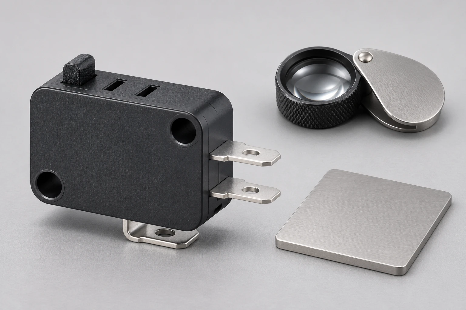
| Evidence item | What to verify | Decision supported |
|---|---|---|
| Identity | Match KW7 configuration, drawing revision and units | Inspect the ordered design |
| Characteristic | Distinguish size, spacing and specified position | Request the right measurement |
| Reference setup | Use approved drawing references and suitable support | Avoid an improvised datum |
| Method capability | Review access, gauge controls and verification | Obtain interpretable evidence |
| Disposition | Link sample results and decision rule to the order | Close the actual acceptance question |
Use the specified reference features without improvising them
A measurement needs a defined reference setup. Identify the surfaces or other features specified by the approved drawing and how the part will be located for inspection. If the drawing is ambiguous, obtain clarification from the design owner. Do not turn the nearest flat surface into a contractual datum simply because it is easy to clamp.
The NIST dimensional measurement programme describes traceable dimensional measurement and the role of controlled methods. Its relevance here is the quality of the measurement basis. It provides no KW7 datum system or tolerance, and citing it does not establish that a particular supplier inspection has been performed by NIST.
Keep the physical locating method in the report. State whether the part was freely supported, located against reference surfaces or restrained in a fixture. The responsible inspection provider should confirm that this setup is suitable for the required characteristic. Excessive restraint can create a condition different from the one the drawing intends to assess.
Choose a method capable of answering the actual question
Ask the laboratory whether optical measurement, coordinate measurement, a defined gauge or another suitable method can evaluate the selected features. Access, material, hole geometry and the requirement all matter. A handheld caliper can support some size checks, but do not assume it establishes a complete hole-position evaluation on a small molded component.
The NPL CMM verification information explains the role of verification artefacts for coordinate measuring machines. It supports asking about measurement capability and checks. It does not make a CMM mandatory for every switch inspection or establish a particular accuracy for the equipment used by the supplier.
Where a functional gauge is proposed, ask which requirement it represents and how the gauge itself is controlled. Passing a trial fixture can answer a defined assembly question. It should not be described as a complete dimensional report unless the approved inspection plan gives it that role. Retain the gauge identity and decision basis with the result.
Avoid confusing a visible hole edge with a defined axis
Before measurement, inspect the part condition and identify the intended feature. A molded edge, chamfer, flash or local damage can affect what is visible in an image. Record the observation and let the qualified provider define how the feature is evaluated under the selected method. Do not manually select a convenient edge that produces the desired result.
If an optical system is used, document the relevant setup and feature-selection approach so that another reviewer can interpret the result. If a contact method is used, record the applicable probing and support basis. The level of detail should fit the requirement; a report must explain enough to distinguish a measurement difference from a change in evaluation method.
Preserve questionable samples before scraping, drilling or forcing a fastener through the hole. Such interventions can change the feature and erase the as-received condition. This guide gives no rework allowance or repair instruction. Refer any proposed modification to the authorized engineering process and keep modified samples separate from incoming acceptance specimens.
Make the report traceable to individual samples
Request the part code, drawing revision, lot or order identity, sample identifiers and measured characteristics. Include the instrument or gauge identification and relevant calibration or verification status. A statement that mounting holes passed is incomplete when it does not identify what was checked or where the supporting observations can be found.
Keep individual results where the acceptance plan needs them. Repeated readings of one hole should remain distinguishable from results across different holes or switches. Explain any repeat measurement and retain its original result. Do not average unlike characteristics into a single number or use repeated trials to conceal a disputed specimen.
Agree how borderline results and measurement uncertainty will be considered before testing. The quality or engineering team should own the decision rule. This article supplies no universal uncertainty ratio, sample size or acceptance boundary. Those details depend on the actual drawing, risk and inspection agreement, rather than on a generic switch family name.
Keep mounting geometry separate from electrical and actuator checks
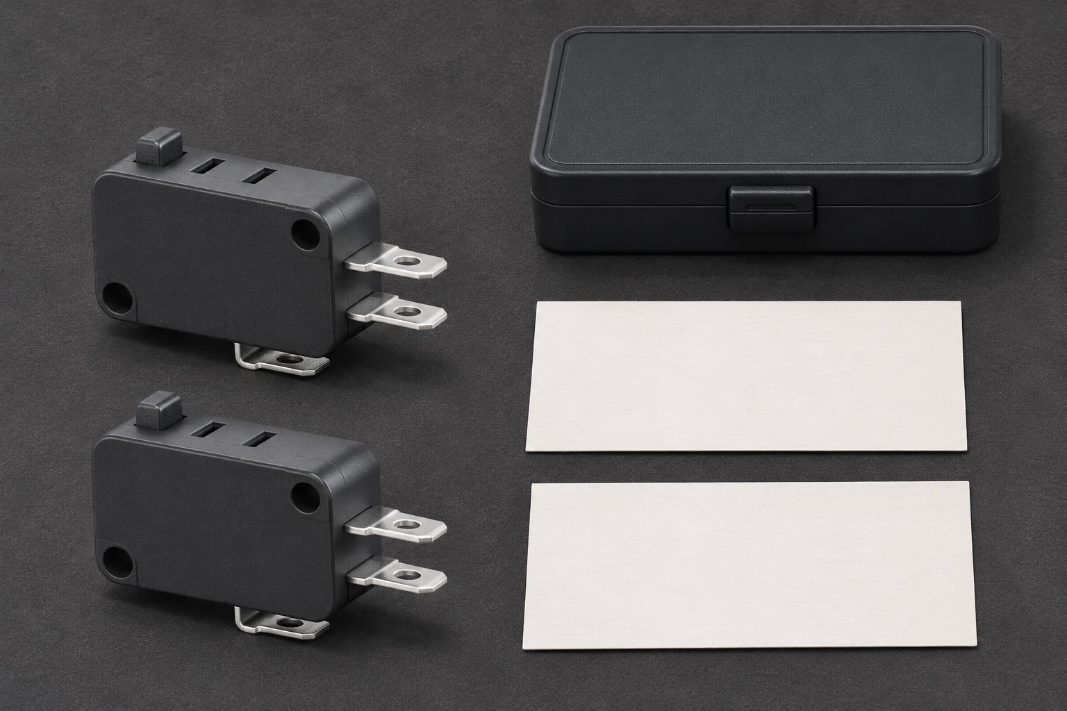
Correct mounting-hole geometry does not establish operating force, travel, contact performance or electrical rating. The installed actuator relationship still requires its own review. The micro switch tolerance stack review addresses how several component relationships can affect the assembly even when an individual mounting characteristic is acceptable.
The terminal configuration guide concerns a different feature set, including connection styles. A terminal report should not be accepted as evidence of mounting-hole position, and mounting measurements should not be used to claim terminal alignment. Keeping these subjects distinct helps the buyer request the correct evidence without duplicating an unrelated investigation.
Fastening also needs the selected product and application guidance. A dimensional report does not authorize arbitrary screw torque, a new fastener size or use of the housing as an assembly stop. If a component seats incorrectly, preserve its condition and check the complete installation plan. Avoid forcing assembly to demonstrate that the measured pattern must be acceptable.
Use a clear supplier request and close the evidence gap
Send the selected KW7 code, controlled drawing and revision, the relevant bracket information and a description of the concern. Identify the exact characteristics to be reported and the proposed specimen basis. Ask whether an existing production report covers that requirement or a new inspection is needed. This makes the request specific enough for an accurate supplier response.
If two reports disagree, first compare part identity, revision, reference setup and evaluation method. A disagreement does not automatically prove that either party measured incorrectly. Resolve those differences before commissioning another set of readings. Where necessary, agree a common method and retain identified specimens so both sides examine the same question.
Record the final disposition against the order: accepted to the specified requirement, held for a missing measurement, or referred for drawing clarification. Link any approved change to its new revision and evidence. Keep that decision available for repeat orders, while preserving the separate records required for electrical suitability and the finished equipment application.
Further learning
This IIT KANPUR-NPTEL laboratory lesson explains coordinate measurement as background for discussing an inspection method. It does not show a KW7 inspection or establish its hole-position tolerance.

Frequently asked questions
Does a screw fitting through both holes prove position?
It can support a defined assembly observation, but it does not automatically evaluate every drawing requirement.
Is one centre-spacing measurement sufficient?
Only for the characteristic it actually measures. Other relationships require the appropriate drawing references and inspection method.
Does this guide give KW7 mounting-hole tolerances?
No. Obtain the controlled drawing for the selected housing and ordering configuration.
Can mounting-hole inspection prove switch operation?
No. Geometry, actuator behaviour and electrical performance require their own relevant evidence.