CENTRO DE NOTÍCIAS LEMA

Notícias e Blog

Centro de Notícias

Comprimento do Cabo do Interruptor de Pé e Alívio de Tensão para Controlos de Equipamentos
Blog LEMA Electric

Comprimento do Cabo do Interruptor de Pé e Alívio de Tensão para Controlos de Equipamentos

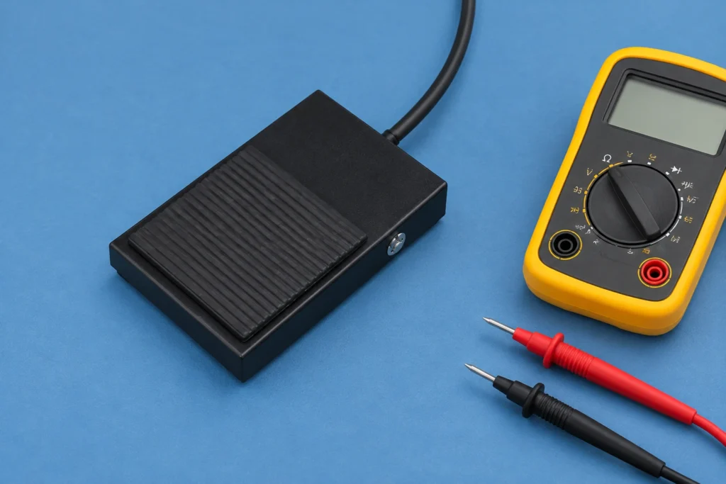
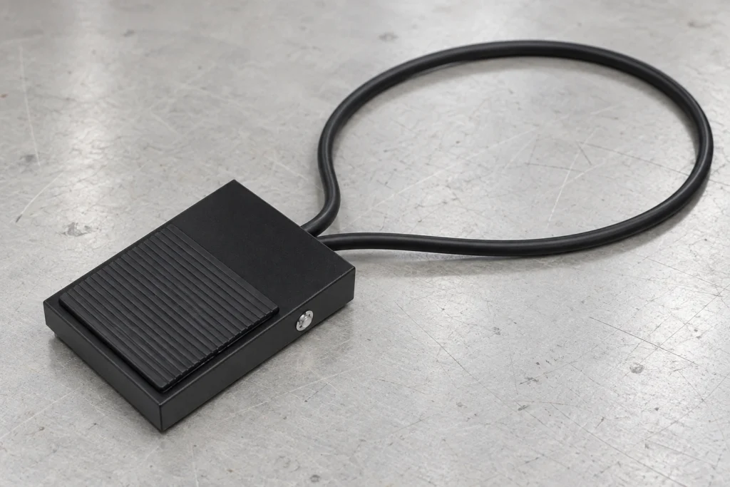
A foot switch cable should reach the intended operating position without pulling on the pedal, connector or internal terminals. Choose its length from the actual route, then verify conductor requirements, electrical interface, environmental exposure and strain relief. A longer cable is not automatically a better cable. Excess slack can create a trip or snag hazard, while a short lead can drag the pedal out of position. This guide covers industrial equipment command pedals, not amplifier accessories. The machine designer must approve the complete pedal, cable and control interface before operation; connector appearance alone cannot establish compatibility. Start with the command circuit, not the cable length Identify what the pedal actually controls. It may close a contact into a low-voltage controller, switch a relay circuit or form part of a manufacturer-defined interface. Those arrangements have different conductor, insulation and protection requirements. Do not assume that a familiar plug carries only a harmless signal. Read the equipment drawing, record the original pedal order code and confirm the supply and receiving input specifications before choosing a cable assembly. A guitar footswitch cable may use a connector that looks similar to an industrial command lead. That resemblance does not prove matching pin assignments, contact action, protective-earth requirements or input behavior. Likewise, an audio shield does not automatically serve as a protective conductor. If the machine documentation is unavailable, keep the equipment out of service until its electrical interface can be established by a qualified person. Use the LEMA LF foot switch product family as a starting point for a model enquiry. The reference photograph confirms an external pedal and attached lead; it does not establish the lead's exact length, conductor size, pinout or suitability...

Ler mais
Reemplacamento do interruptor de limite industrial: preservação da posição e validação do tempo
Blog LEMA Electric

Reemplacamento do interruptor de limite industrial: preservação da posição e validação do tempo

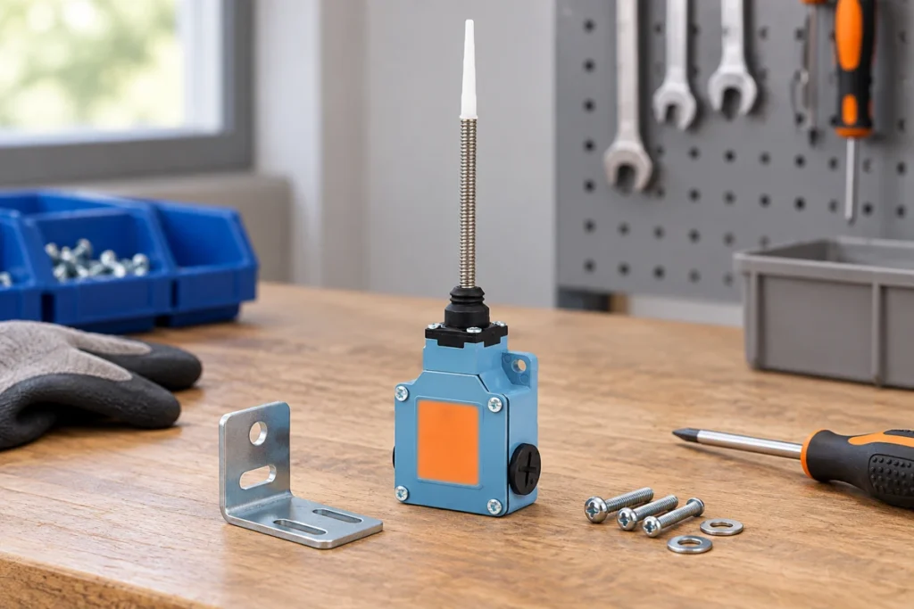
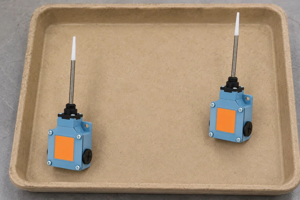
An industrial limit switch replacement must preserve the original contact function, actuator relationship, mounting geometry and electrical duty, then pass the machine's specified acceptance checks. Matching the housing or screw holes alone does not prove that the new part operates at the same machine position. Record the installation before removal and compare the original and candidate order codes against current drawings. This guide covers mechanical equipment position switches, not furnace temperature-limit devices. It explains how to protect an established setup during an approved repair; it does not guarantee unchanged timing or authorise substituting a generic switch into a safety-related function. Confirm the fault and the approved service scope Establish why a replacement is needed before ordering it. A loose bracket, worn target, cable defect or receiving-input problem can resemble a failed switch. Replacing a sound component can leave that problem unresolved and introduce a new operating-point difference. Use the position-switch troubleshooting guide to organise fault evidence before moving the installation. For the broader position-detection context, see the limit switch application guide. Read the equipment service instructions and approved parts information. Identify whether the repair requires an exact service part, an approved alternative or a formal design review. A component used for ordinary position indication may have different verification requirements from one participating in a protective function. Do not assume an alternate model is acceptable because a supplier describes it as suitable for industrial machinery. Secure the machine using its authorised isolation process, including stored mechanical, pneumatic or hydraulic energy where relevant. OSHA's hazardous-energy control standard is a United States workplace reference for that process within its scope. A limit-switch signal, stop command or controller mode is not a substitute for...

Ler mais
Resistência de Contacto das Tomadas Elétricas: Medição e Aumento da Temperatura
Blog LEMA Electric

Resistência de Contacto das Tomadas Elétricas: Medição e Aumento da Temperatura

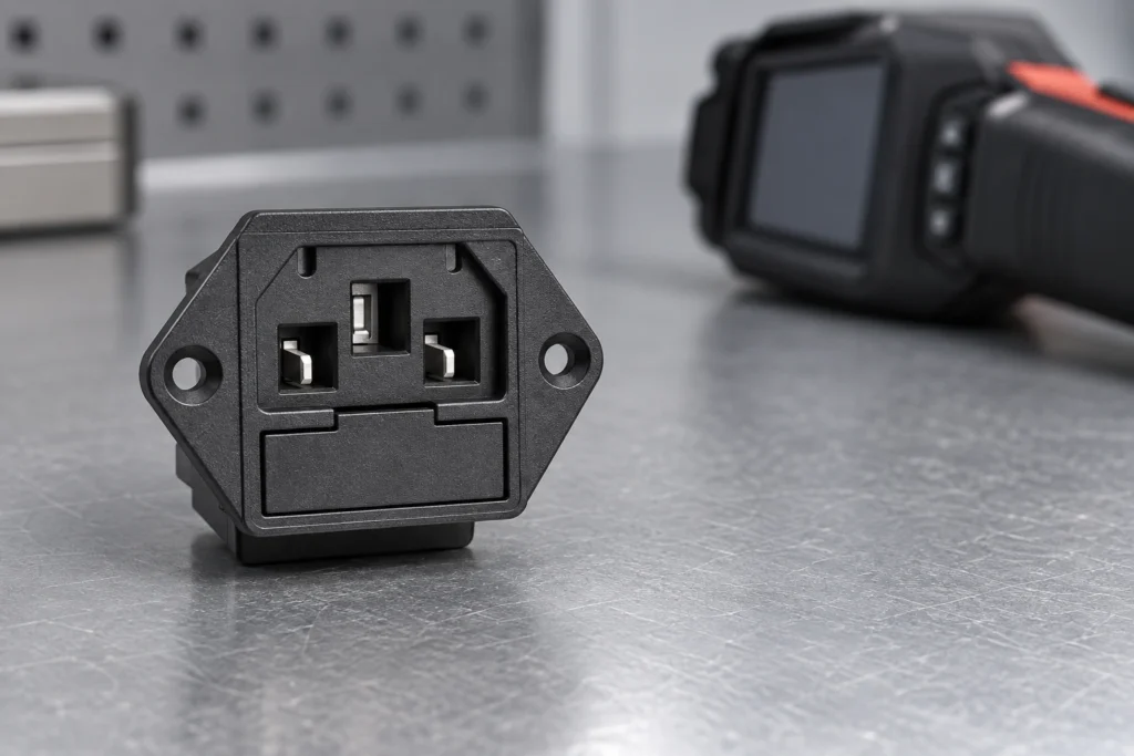
Power socket contact resistance adds electrical loss at the mating interface. Under a given current, a higher resistance produces more local power dissipation, but resistance alone does not predict the final temperature. The contact geometry, surrounding materials, ventilation and operating conditions also matter. For an equipment inlet, evaluate the complete mated connection and the actual application. Start with an isolated, repeatable resistance measurement and a qualified thermal validation plan. Do not use a continuity beep, a cool exterior surface or an unverified catalog number as proof that the connection is suitable. This guide concerns panel-mounted equipment power sockets and inlets, rather than household wall receptacles or RV shore-power connectors. It focuses on how to interpret contact measurements and plan a heat-rise investigation. Work involving installed mains equipment requires qualified personnel, suitable test equipment and the equipment's documented safety procedure. Define the connection being measured Identify the inlet, mating connector, terminals and measurement points. The resistance between two accessible points may include the mating interface, metal within the inlet, the cable termination and part of the cable. Without a clearly stated test boundary, two apparently different contact-resistance results may simply describe different paths. Record the exact inlet and cord-set identities, their condition and whether they are fully mated. Preserve the mounting arrangement and cable support in the test record. A new loose sample on a bench is not necessarily representative of a connection installed in a warm enclosure. Conversely, a measurement including a long cable cannot be described as the inlet's contact resistance alone. The University of Maryland CALCE contact-resistance measurement overview describes evaluation using actual contact geometry and controlled environmental conditions. It supports a central practical distinction: measure the connection...

Ler mais
Modos de falha do microinterruptor: evidências e verificações da causa raiz
Blog LEMA Electric

Modos de falha do microinterruptor: evidências e verificações da causa raiz

Micro switch failure modes include a contact that will not establish the intended state, a contact that remains closed, intermittent electrical behavior, and a mechanism that no longer operates at the required position. The useful question is what changed before the failure. Inspect the load, actuator movement, mounting, environment and connection system separately. Replacing a switch without preserving this evidence may restore operation briefly while leaving the original cause in the machine. This guide organizes a root-cause investigation for conventional snap-action micro switches; it does not diagnose a specific returned LEMA part. Begin with the machine's reported symptom and the expected contact function. A controller alarm alone cannot prove that the switch failed. A disconnected cable, changing process position or incorrect input configuration can produce a similar result. Treat the switch as one component in a documented chain from physical movement to accepted control signal. Preserve the evidence before changing the installation Record the switch order code, equipment identity and the last known successful operation. Photograph the installed actuator, terminal connection, bracket and surrounding mechanism before loosening anything. Include the operating conditions at the time of the event: a production change, maintenance visit, washdown, new load, cable rerouting or adjustment may explain why an established installation suddenly changed. Label a removed switch with the machine and position it came from. Keep associated connectors and fastening parts when they may contribute to the investigation. Avoid opening a sealed housing, washing away residue or repeatedly working the actuator before its condition has been recorded. A supplier cannot assess the original condition when cleaning or exploratory damage has already altered it. Separate observations from conclusions in the return record. “Input stayed active after...

Ler mais
Contacto do microinterruptor: validar os eventos de entrada do mecanismo
Blog LEMA Electric

Contacto do microinterruptor: validar os eventos de entrada do mecanismo

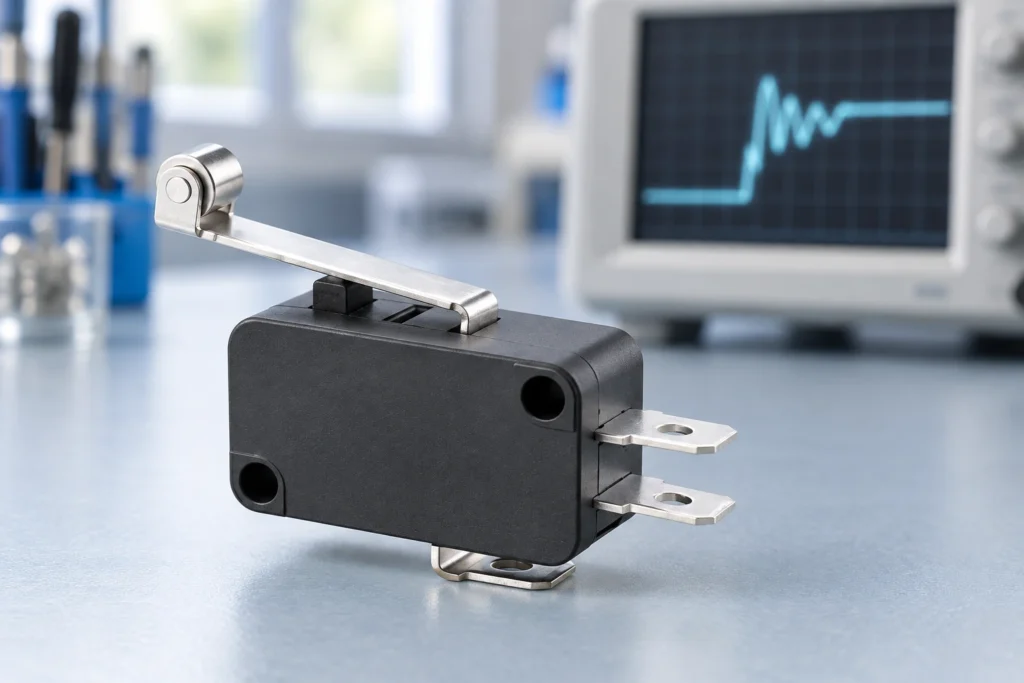
Micro switch contact bounce is a brief series of electrical transitions around a single mechanical switching event. A snap-action mechanism makes the change decisive, but it does not guarantee that a fast controller sees exactly one edge. For a roller-lever or plunger micro switch on an OEM machine, investigate both the contact signal and the motion that operates it. Then accept a stable state or a qualified event at the controller. A debounce delay alone cannot correct a cam that repeatedly crosses the operating point, an overloaded contact, or a damaged harness. This guide focuses on micro switches operated by mechanisms: rollers following cams, plungers touched by moving parts, and small levers detecting position. It addresses event validation, not a generic replacement procedure or a fixed debounce circuit. Start with the actual switch drawing, the controller input specification and a record of the machine movement. The aim is to reject unintended transitions without hiding a genuine position change. Separate one switching event from repeated mechanical actuation A useful first question is whether the actuator makes one controlled pass through the switch point. Contact bounce occurs during contact settling. Mechanical re-actuation occurs when the moving part repeatedly operates and releases the switch. Both can produce multiple edges, but they require different corrections. A loose roller bracket, oscillating linkage or cam dwelling near the release point can keep creating valid mechanical changes long after the first contact transition. The University of Washington Makeability Lab lesson on debouncing explains how moving electrical contacts can oscillate before settling. Use that principle to interpret a short transition cluster, while separately checking whether the machine motion continues to cross the switching boundary. Do not label every...

Ler mais
Push Button Switch Replacement: Contacts and Panel Fit
Blog LEMA Electric

Push Button Switch Replacement: Contacts and Panel Fit

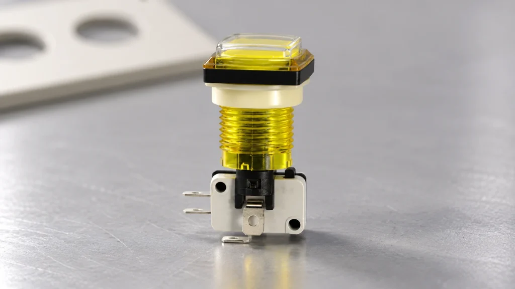
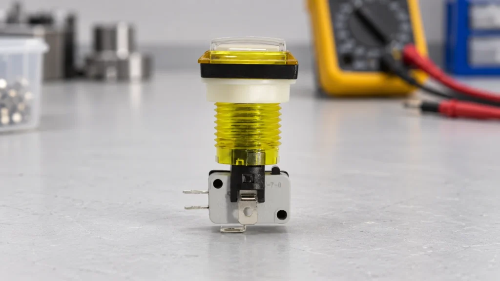
Replace the complete function, not only the visible button A push button switch replacement must preserve the original action, contact arrangement, panel fit, electrical duty and terminal system. If the button is illuminated, the indicator circuit also needs a separate comparison. A similar cap color or the same number of pins does not establish compatibility. Start with the equipment instructions and complete original order code, then compare a current drawing and contact diagram for the candidate. This guide focuses on equipment panel controls and OEM substitution checks; it does not authorize changes to emergency stops, safety interlocks or proprietary service assemblies. The LEMA push button switch range offers product families to review against an application specification. Product photographs can help identify external features, but they cannot prove a contact circuit, cutout dimension or approval. The replacement needs a documented comparison and a defined acceptance test before it enters service. The industrial push button selection guide provides the broader application framework. Use this replacement checklist to compare the original assembly and candidate against that specification, rather than choosing a new circuit function. Decide whether the actuator, contact assembly or entire unit needs replacement Confirm the fault before ordering parts. A jammed cap, damaged contact, loose terminal and failed indicator can produce different symptoms. Use the complementary push button troubleshooting guide to separate those faults. A wiring defect or incorrect control-input configuration will not be corrected by installing a new button. Some panel controls use separate actuator and contact blocks; others are supplied as an integrated assembly. Follow the manufacturer's service instructions. Do not assume contact blocks from different series fit together because their clips look similar. A mechanical attachment can appear...

Ler mais
Reposição do interruptor de ligar/desligar: Polos, lançamentos e classificações
Blog LEMA Electric

Reposição do interruptor de ligar/desligar: Polos, lançamentos e classificações

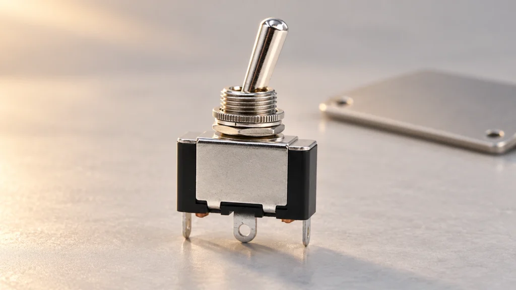
Preserve the original switching function A toggle switch replacement needs to match poles, throws, maintained or momentary action, contact ratings, panel mounting and terminal arrangement. The same number of pins or a similar metal lever does not establish interchangeability. Begin with the equipment circuit and original order code, build a contact-state table, and compare the candidate's current specification. For OEM equipment, a different part is a controlled substitution that requires functional validation. This guide focuses on panel-mounted equipment controls, including the LEMA toggle switch range, rather than household wall-switch wiring, musical-instrument modifications or vehicle-specific repairs. If the equipment manufacturer specifies an approved service part, use that instruction as the starting point. A generic selection checklist cannot override approval requirements or establish that an unlisted component is suitable. Preserve the original machine function and investigate why the old part failed before installing another switch. For the wider operating principle and selection context, see the toggle switch mechanism guide. For a termination comparison, use the solder, screw and quick-connect terminal guide. These references support the replacement comparison; the exact part drawing still controls acceptance. Document the old switch and its circuit Collect the complete switch markings, part number and any suffix. Photograph the actuator, panel mounting and terminal side after following the equipment isolation procedure. Note the orientation of the lever and any locating tab, keyed washer or anti-rotation feature. Record which position corresponds to the displayed equipment command and which circuits are connected in that position. Identify the connected load from the diagram. A toggle can carry load current directly, operate a relay coil or provide a controller input. Those roles impose different requirements. Document voltage, AC or DC, steady current...

Ler mais
Substituição do Microinterruptor: Compatibilidade em Forma, Encaixe e Funcionamento
Blog LEMA Electric

Substituição do Microinterruptor: Compatibilidade em Forma, Encaixe e Funcionamento

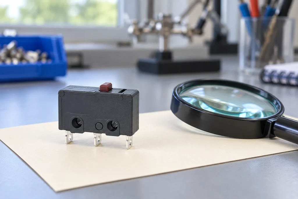
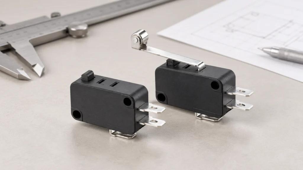
Match the replacement to the machine, not just the switch body A micro switch replacement must match the original contact function, mounting geometry, actuator movement, terminal arrangement and electrical duty. A switch that fits the screw holes can still change the operating point, reverse a control signal or fail prematurely under the connected load. Start with the equipment service instructions and the complete original part number, then compare the proposed replacement against a current drawing and rating sheet. For industrial and appliance assemblies, treat an undocumented substitution as an engineering change requiring validation. This guide explains how to build that comparison without assuming that similar-looking switches are interchangeable. The scope here is a mechanically actuated snap-action component, such as the models in the LEMA micro switch range. It does not provide an approval to replace a machine safety device, a sealed appliance assembly or a manufacturer's proprietary service part. Those cases may require an exact approved component or a complete assembly. Do not bypass an interlock to keep equipment running while a replacement is being sourced. Record the original installation before removing anything Identify the equipment, assembly revision and original switch order code. Photograph the switch from the actuator, mounting and terminal sides, with the circuit isolated. Record the markings exactly, including voltage, current, temperature codes and any separate load-specific ratings. A supplier logo or a partial family name is not enough: terminals, actuators and contact materials can vary within one product family. Record how the actuator contacts the moving mechanism. Note whether a cam touches a roller, a bracket presses a plunger, or a door deflects a lever. Include the normal rest position and the position at which the...

Ler mais
Troubleshooting do interruptor de botão: Conectores, circuito elétrico e entradas de controle
Blog LEMA Electric

Troubleshooting do interruptor de botão: Conectores, circuito elétrico e entradas de controle

A solução de problemas com interruptores de botão funciona melhor quando se identificam quatro possíveis falhas: o atuador, os contatos elétricos, a fiação e o circuito de controle receptor. Um botão que parece estar funcionando normalmente ainda pode apresentar uma conexão defeituosa; um contato funcional ainda pode enviar um sinal que a máquina ignora. Comece com o diagrama elétrico e os estados de liberação e pressão esperados, isolando então a máquina antes de inspecionar ou medir o interruptor. Este guia ajuda os fabricantes de equipamentos industriais e as equipes de manutenção a localizar a falha sem presumir que todas as avarias exigem um novo botão. Os exemplos se referem a entradas de controle comuns. Paradas de emergência, circuitos de proteção e outras funções de proteção exigem procedimentos e validações aprovados. Nunca desative um dispositivo de proteção para manter a produção em funcionamento. Registre o sintoma antes de mover quaisquer fios. Anote exatamente o que está dando defeito: ausência de resposta, resposta retardada, várias respostas após um único toque, botão que permanece no lugar ou indicador que deixa de funcionar. Registre também se o defeito ocorre após a limpeza, após vibração, ao iniciar a operação ou apenas após a operação do equipamento. Essas condições ajudam a distinguir uma componente danificada de estresse de instalação ou de algum outro problema no circuito. Identifique o código de ordem do interruptor, a revisão do desenho, as designações dos terminais, a tensão de controle, a carga conectada e a ação pretendida. Um botão mantido em posição selecionada deve permanecer assim; um botão que muda de posição momentaneamente deve retornar quando liberado. A confusão entre os dois produz um diagnóstico falso. Compare o dispositivo instalado com a ficha técnica aprovada, em vez de confiar em cores ou aparência. Utilize o guia de seleção de botões industriais para revisar os requisitos originais da aplicação. A solução de problemas deve confirmar essas exigências, não as alterar silenciosamente. Isolar a energia antes de realizar verificações mecânicas ou de continuidade:...

Ler mais
Como testar um interruptor de pé: verificação de contato isolado e cabo
Blog LEMA Electric

Como testar um interruptor de pé: verificação de contato isolado e cabo

Para testar um interruptor de pé, identifique sua função de contato pretendida, isolando-o e desconectando-o da fonte de energia de forma segura, e verifique o par de contato especificado tanto em estado aberto quanto em estado de operação. Um multímetro pode ajudar a verificar se um interruptor mecânico comum apresenta um circuito aberto ou uma conexão inconsistente. Ele não pode determinar a capacidade de carga de um pedal, a homologação de segurança ou a adequação a uma determinada máquina. Este guia aborda um registro de inspeção repetível para controles de pé industriais, incluindo o pedal, o cabo e o conector, para que você possa identificar uma falha no interruptor em relação a um problema no cabo ou no controlador. Não aplique este procedimento sem modificações a controles de pé eletrônicos, de velocidade variável, médicos ou com classificação de segurança. Os seus circuitos e requisitos de verificação podem ser diferentes. Siga a documentação exata do equipamento e do pedal. Identifique o dispositivo antes de escolher uma verificação. Um dispositivo com acionamento por pé pode ser um simples interruptor de contato, um potenciômetro, um sensor eletrônico ou um controle de várias fases. Alguns conjuntos de pedal têm vários contatos independentes. Outros enviam um sinal codificado para um controlador. Testar cada par de fios como se fossem contatos secos pode gerar resultados enganosos ou danificar um conjunto eletrônico. Leia o código de ordem e o diagrama de terminais. Registre se a ação é momentânea ou permanente, se o contato pretendido é normalmente aberto ou normalmente fechado e se o conector contém circuitos adicionais. Não inferir a função a partir da forma do conector, das cores dos fios ou do aspecto de um pedal semelhante. O desenho relevante deve descrever o código de ordem específico a ser testado. O guia de seleção de interruptores elétricos industriais explica as questões mais amplas relacionadas à especificação. Este guia de testes concentra-se na localização de uma falha existente sem alterar essas exigências. Prepare um teste isolado e controlado. Siga o procedimento de controle de energia do local e verifique se a instalação é segura...

Ler mais
Interruptor de pé para controle de bomba: ação, interface e checklist para OEM
Blog LEMA Electric

Interruptor de pé para controle de bomba: ação, interface e checklist para OEM

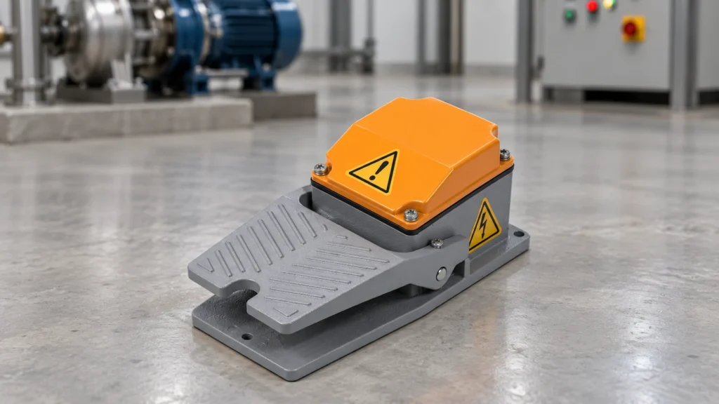
Um interruptor de pé para uma bomba normalmente deve ser selecionado como parte do sistema de controle da bomba: definir a ação do pedal necessária, identificar o dispositivo de entrada ou de comutação e verificar a funcionalidade elétrica completa antes de conectar uma carga. Um pedal instantâneo pode solicitar a bomba enquanto é mantido pressionado; um pedal mantido pode solicitar um estado contínuo. Nenhuma dessas ações proporciona automaticamente uma parada segura, uma dosagem precisa ou proteção contra reinícios inesperados. Este guia fornece aos fabricantes de equipamentos uma lista de verificação prática e de especificações para controles elétricos de pedal utilizados em operações de bombeamento. Trata-se de um dispositivo de comando elétrico, não de uma bomba mecânica acionada por pedal ou de uma válvula pneumática. Um pedal industrial comum não deve ser considerado adequado para fins médicos, fluidos perigosos ou funções de segurança sem a avaliação do sistema aplicável. Defina a tarefa de bombeamento antes de escolher o pedal. O operador precisa de ambas as mãos para posicionar um recipiente, segurar um tubo ou alinhar um dispositivo? A função de comando destina-se a fazer a bomba funcionar continuamente, solicitar um ciclo cronometrado ou permitir que um processo ocorra apenas enquanto o pedal estiver pressionado? Estas são funções de controle diferentes. O mesmo pedal físico pode produzir comportamentos muito diferentes da máquina, dependendo do circuito receptor. Registre os riscos de pressão e movimento, a exposição a respingos, a presença de equipamentos móveis próximos e a posição do operador. Uma função de comando sem mão pode ser conveniente enquanto se introduz um novo risco de operação acidental. Decida como a máquina como um todo evita esse evento antes de especificar a cor ou o material da carcaça do pedal. O guia de seleção de comutadores industriais fornece o quadro mais amplo de seleção de componentes. As perguntas específicas para bombas abaixo devem fazer parte da especificação e da aceitação do equipamento...

Ler mais
Tipos de cabeças de interruptor de limite e posições ajustáveis do atuador
Blog LEMA Electric

Tipos de cabeças de interruptor de limite e posições ajustáveis do atuador

As cabeças de comutação devem ser selecionadas de acordo com o movimento pretendido, a direção de aproximação permitida e a distância de deslocamento do tipo de comutador específico. As alavancas de rolamento, os mancais, as hastes e outras formas de acionamento não são intercambiáveis simplesmente porque detectam a posição. Algumas construções permitem que a cabeça seja reposicionada de acordo com um procedimento definido; outras não. Confirme a combinação completa de cabeça e corpo, as opções de orientação e as instruções antes de substituir um comutador instalado. Este guia concentra-se na seleção e na orientação da cabeça para comutadores mecânicos de posição. Complementa as informações sobre os diversos tipos de acionadores e as guias de montagem, em vez de fornecer instruções universais para a troca de qualquer cabeça. As imagens do comutador LEMA LZ1 são a referência real do produto; seu aspecto externo não comprova a intercambiabilidade com outras séries. Desconecte a cabeça da identidade completa do comutador: um conjunto de comutadores de posição inclui o corpo, a disposição dos contatos, a cabeça, o acionador e a montagem. Uma cabeça de substituição deve corresponder à família relevante e à combinação homologada. Modelos de parafusos ou formas de alojamento semelhantes não comprovam que a relação de funcionamento interna, a vedação ou a deslocação sejam corretas. Ordenar e inspecionar a construção completa identificada. Registar os códigos do corpo e da cabeça quando o fabricante os fornecer. Se a cabeça não estiver disponível separadamente ou não existir informação de intercâmbio homologada, não se deve presumir que se trate de uma peça de reposição. Solicitar a opção de substituição completa em vez disso. Isso evita substituir uma cabeça fixada fisicamente que altera a operação elétrica ou mecânica sem uma base de aceitação estabelecida. Descrição da abordagem pretendida em três dimensões Identificar onde o alvo móvel entra em contato com o atuador e como ele se aproxima, passa e sai. Uma alavanca de rolamento pode adequar-se a um perfil de curso, enquanto um pistão pode ser adequado a uma direção de pressão controlada. Um braço ou atuador flexível pode detectar movimento sobre...

Ler mais