LEMA NACHRICHTENZENTRUM

Nachrichten & Blog

Nachrichtenzentrum

Länge des Fußschaltsatzes und Dehnungsentlastung für Gerätebedienung
Blog LEMA Electric

Länge des Fußschaltsatzes und Dehnungsentlastung für Gerätebedienung

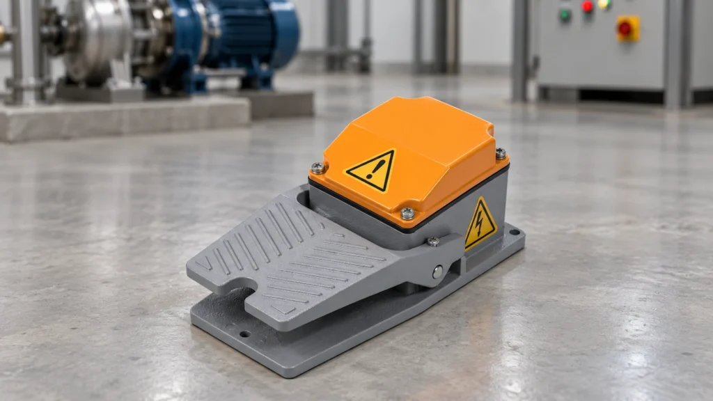
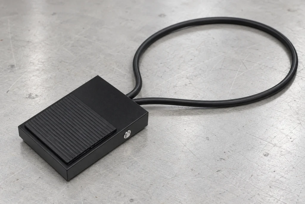
A foot switch cable should reach the intended operating position without pulling on the pedal, connector or internal terminals. Choose its length from the actual route, then verify conductor requirements, electrical interface, environmental exposure and strain relief. A longer cable is not automatically a better cable. Excess slack can create a trip or snag hazard, while a short lead can drag the pedal out of position. This guide covers industrial equipment command pedals, not amplifier accessories. The machine designer must approve the complete pedal, cable and control interface before operation; connector appearance alone cannot establish compatibility. Start with the command circuit, not the cable length Identify what the pedal actually controls. It may close a contact into a low-voltage controller, switch a relay circuit or form part of a manufacturer-defined interface. Those arrangements have different conductor, insulation and protection requirements. Do not assume that a familiar plug carries only a harmless signal. Read the equipment drawing, record the original pedal order code and confirm the supply and receiving input specifications before choosing a cable assembly. A guitar footswitch cable may use a connector that looks similar to an industrial command lead. That resemblance does not prove matching pin assignments, contact action, protective-earth requirements or input behavior. Likewise, an audio shield does not automatically serve as a protective conductor. If the machine documentation is unavailable, keep the equipment out of service until its electrical interface can be established by a qualified person. Use the LEMA LF foot switch product family as a starting point for a model enquiry. The reference photograph confirms an external pedal and attached lead; it does not establish the lead's exact length, conductor size, pinout or suitability...

Mehr lesen
Industrieller Limitschalterersatz: Position beibehalten und Timing validieren
Blog LEMA Electric

Industrieller Limitschalterersatz: Position beibehalten und Timing validieren

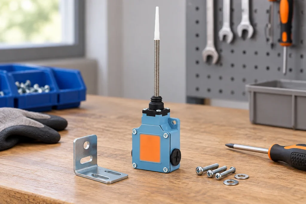
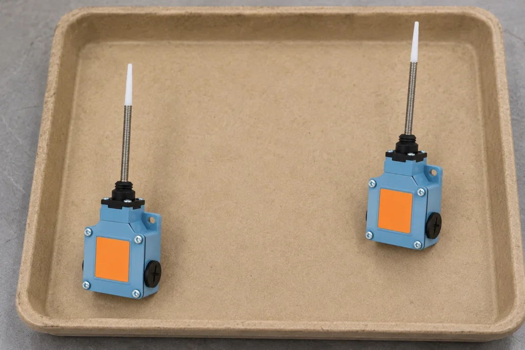
An industrial limit switch replacement must preserve the original contact function, actuator relationship, mounting geometry and electrical duty, then pass the machine's specified acceptance checks. Matching the housing or screw holes alone does not prove that the new part operates at the same machine position. Record the installation before removal and compare the original and candidate order codes against current drawings. This guide covers mechanical equipment position switches, not furnace temperature-limit devices. It explains how to protect an established setup during an approved repair; it does not guarantee unchanged timing or authorise substituting a generic switch into a safety-related function. Confirm the fault and the approved service scope Establish why a replacement is needed before ordering it. A loose bracket, worn target, cable defect or receiving-input problem can resemble a failed switch. Replacing a sound component can leave that problem unresolved and introduce a new operating-point difference. Use the position-switch troubleshooting guide to organise fault evidence before moving the installation. For the broader position-detection context, see the limit switch application guide. Read the equipment service instructions and approved parts information. Identify whether the repair requires an exact service part, an approved alternative or a formal design review. A component used for ordinary position indication may have different verification requirements from one participating in a protective function. Do not assume an alternate model is acceptable because a supplier describes it as suitable for industrial machinery. Secure the machine using its authorised isolation process, including stored mechanical, pneumatic or hydraulic energy where relevant. OSHA's hazardous-energy control standard is a United States workplace reference for that process within its scope. A limit-switch signal, stop command or controller mode is not a substitute for...

Mehr lesen
Power Socket Contact Resistance: Measurement and Heat Rise
Blog LEMA Electric

Power Socket Contact Resistance: Measurement and Heat Rise

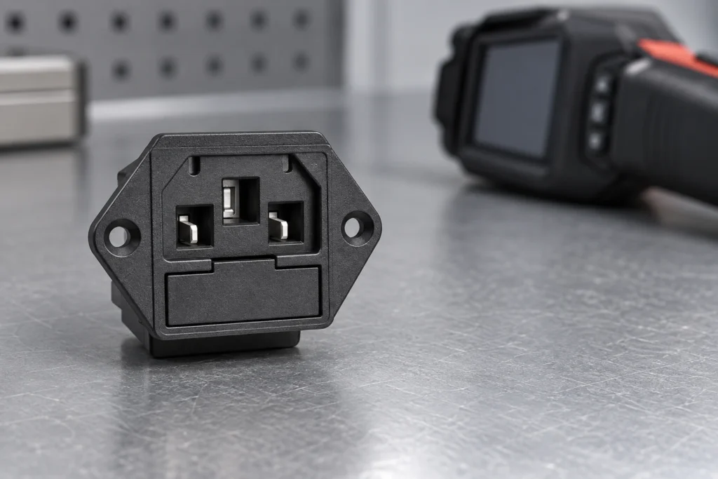
Power socket contact resistance adds electrical loss at the mating interface. Under a given current, a higher resistance produces more local power dissipation, but resistance alone does not predict the final temperature. The contact geometry, surrounding materials, ventilation and operating conditions also matter. For an equipment inlet, evaluate the complete mated connection and the actual application. Start with an isolated, repeatable resistance measurement and a qualified thermal validation plan. Do not use a continuity beep, a cool exterior surface or an unverified catalog number as proof that the connection is suitable. This guide concerns panel-mounted equipment power sockets and inlets, rather than household wall receptacles or RV shore-power connectors. It focuses on how to interpret contact measurements and plan a heat-rise investigation. Work involving installed mains equipment requires qualified personnel, suitable test equipment and the equipment's documented safety procedure. Define the connection being measured Identify the inlet, mating connector, terminals and measurement points. The resistance between two accessible points may include the mating interface, metal within the inlet, the cable termination and part of the cable. Without a clearly stated test boundary, two apparently different contact-resistance results may simply describe different paths. Record the exact inlet and cord-set identities, their condition and whether they are fully mated. Preserve the mounting arrangement and cable support in the test record. A new loose sample on a bench is not necessarily representative of a connection installed in a warm enclosure. Conversely, a measurement including a long cable cannot be described as the inlet's contact resistance alone. The University of Maryland CALCE contact-resistance measurement overview describes evaluation using actual contact geometry and controlled environmental conditions. It supports a central practical distinction: measure the connection...

Mehr lesen
Fehlerszenarien bei Mikroschaltern: Nachweise und Ursachenanalysen
Blog LEMA Electric

Fehlerszenarien bei Mikroschaltern: Nachweise und Ursachenanalysen

Micro switch failure modes include a contact that will not establish the intended state, a contact that remains closed, intermittent electrical behavior, and a mechanism that no longer operates at the required position. The useful question is what changed before the failure. Inspect the load, actuator movement, mounting, environment and connection system separately. Replacing a switch without preserving this evidence may restore operation briefly while leaving the original cause in the machine. This guide organizes a root-cause investigation for conventional snap-action micro switches; it does not diagnose a specific returned LEMA part. Begin with the machine's reported symptom and the expected contact function. A controller alarm alone cannot prove that the switch failed. A disconnected cable, changing process position or incorrect input configuration can produce a similar result. Treat the switch as one component in a documented chain from physical movement to accepted control signal. Preserve the evidence before changing the installation Record the switch order code, equipment identity and the last known successful operation. Photograph the installed actuator, terminal connection, bracket and surrounding mechanism before loosening anything. Include the operating conditions at the time of the event: a production change, maintenance visit, washdown, new load, cable rerouting or adjustment may explain why an established installation suddenly changed. Label a removed switch with the machine and position it came from. Keep associated connectors and fastening parts when they may contribute to the investigation. Avoid opening a sealed housing, washing away residue or repeatedly working the actuator before its condition has been recorded. A supplier cannot assess the original condition when cleaning or exploratory damage has already altered it. Separate observations from conclusions in the return record. “Input stayed active after...

Mehr lesen
Mikroschalter-Kontaktprellen: Mechanismus-Eingabeereignisse validieren
Blog LEMA Electric

Mikroschalter-Kontaktprellen: Mechanismus-Eingabeereignisse validieren

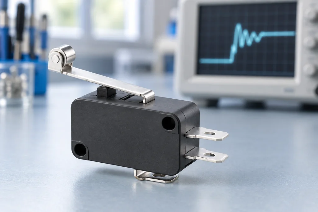
Micro switch contact bounce is a brief series of electrical transitions around a single mechanical switching event. A snap-action mechanism makes the change decisive, but it does not guarantee that a fast controller sees exactly one edge. For a roller-lever or plunger micro switch on an OEM machine, investigate both the contact signal and the motion that operates it. Then accept a stable state or a qualified event at the controller. A debounce delay alone cannot correct a cam that repeatedly crosses the operating point, an overloaded contact, or a damaged harness. This guide focuses on micro switches operated by mechanisms: rollers following cams, plungers touched by moving parts, and small levers detecting position. It addresses event validation, not a generic replacement procedure or a fixed debounce circuit. Start with the actual switch drawing, the controller input specification and a record of the machine movement. The aim is to reject unintended transitions without hiding a genuine position change. Separate one switching event from repeated mechanical actuation A useful first question is whether the actuator makes one controlled pass through the switch point. Contact bounce occurs during contact settling. Mechanical re-actuation occurs when the moving part repeatedly operates and releases the switch. Both can produce multiple edges, but they require different corrections. A loose roller bracket, oscillating linkage or cam dwelling near the release point can keep creating valid mechanical changes long after the first contact transition. The University of Washington Makeability Lab lesson on debouncing explains how moving electrical contacts can oscillate before settling. Use that principle to interpret a short transition cluster, while separately checking whether the machine motion continues to cross the switching boundary. Do not label every...

Mehr lesen
Push Button Switch Replacement: Contacts and Panel Fit
Blog LEMA Electric

Push Button Switch Replacement: Contacts and Panel Fit

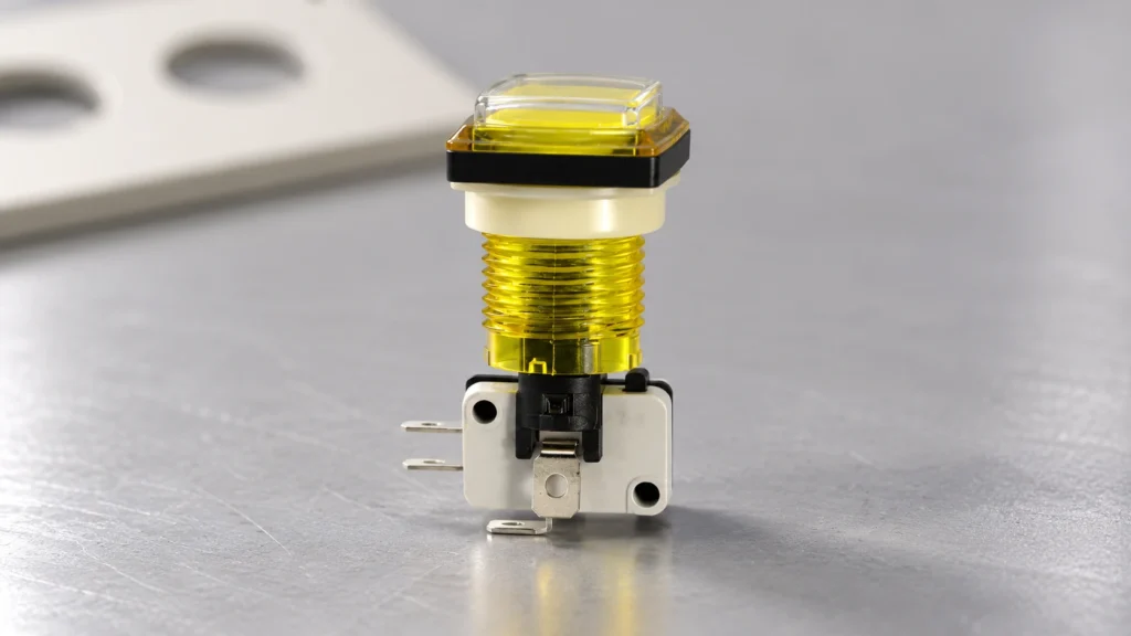
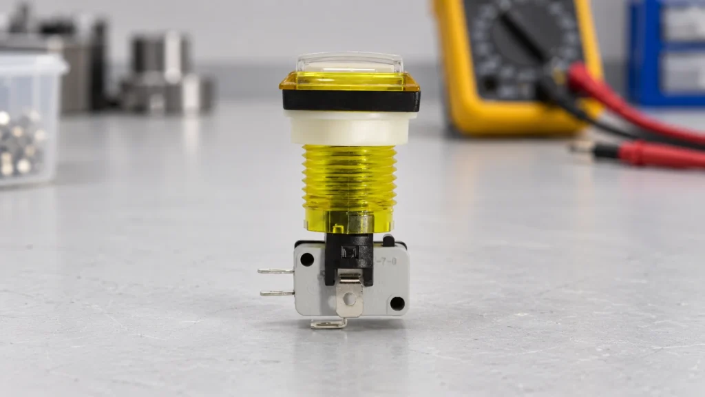
Replace the complete function, not only the visible button A push button switch replacement must preserve the original action, contact arrangement, panel fit, electrical duty and terminal system. If the button is illuminated, the indicator circuit also needs a separate comparison. A similar cap color or the same number of pins does not establish compatibility. Start with the equipment instructions and complete original order code, then compare a current drawing and contact diagram for the candidate. This guide focuses on equipment panel controls and OEM substitution checks; it does not authorize changes to emergency stops, safety interlocks or proprietary service assemblies. The LEMA push button switch range offers product families to review against an application specification. Product photographs can help identify external features, but they cannot prove a contact circuit, cutout dimension or approval. The replacement needs a documented comparison and a defined acceptance test before it enters service. The industrial push button selection guide provides the broader application framework. Use this replacement checklist to compare the original assembly and candidate against that specification, rather than choosing a new circuit function. Decide whether the actuator, contact assembly or entire unit needs replacement Confirm the fault before ordering parts. A jammed cap, damaged contact, loose terminal and failed indicator can produce different symptoms. Use the complementary push button troubleshooting guide to separate those faults. A wiring defect or incorrect control-input configuration will not be corrected by installing a new button. Some panel controls use separate actuator and contact blocks; others are supplied as an integrated assembly. Follow the manufacturer's service instructions. Do not assume contact blocks from different series fit together because their clips look similar. A mechanical attachment can appear...

Mehr lesen
Austausch von Kippschaltern: Pole, Schaltstellungen und Nennwerte
Blog LEMA Electric

Austausch von Kippschaltern: Pole, Schaltstellungen und Nennwerte

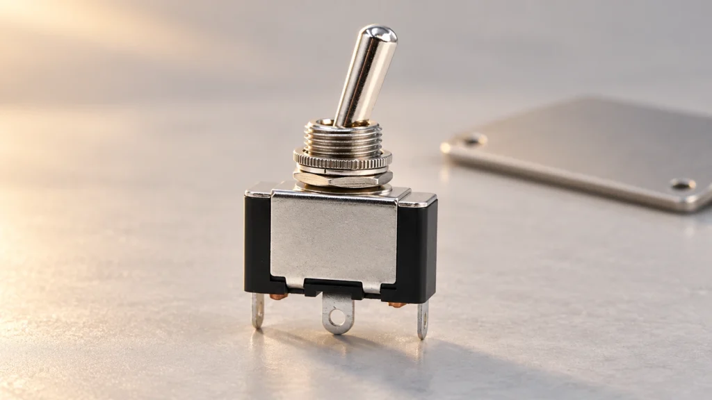
Preserve the original switching function A toggle switch replacement needs to match poles, throws, maintained or momentary action, contact ratings, panel mounting and terminal arrangement. The same number of pins or a similar metal lever does not establish interchangeability. Begin with the equipment circuit and original order code, build a contact-state table, and compare the candidate's current specification. For OEM equipment, a different part is a controlled substitution that requires functional validation. This guide focuses on panel-mounted equipment controls, including the LEMA toggle switch range, rather than household wall-switch wiring, musical-instrument modifications or vehicle-specific repairs. If the equipment manufacturer specifies an approved service part, use that instruction as the starting point. A generic selection checklist cannot override approval requirements or establish that an unlisted component is suitable. Preserve the original machine function and investigate why the old part failed before installing another switch. For the wider operating principle and selection context, see the toggle switch mechanism guide. For a termination comparison, use the solder, screw and quick-connect terminal guide. These references support the replacement comparison; the exact part drawing still controls acceptance. Document the old switch and its circuit Collect the complete switch markings, part number and any suffix. Photograph the actuator, panel mounting and terminal side after following the equipment isolation procedure. Note the orientation of the lever and any locating tab, keyed washer or anti-rotation feature. Record which position corresponds to the displayed equipment command and which circuits are connected in that position. Identify the connected load from the diagram. A toggle can carry load current directly, operate a relay coil or provide a controller input. Those roles impose different requirements. Document voltage, AC or DC, steady current...

Mehr lesen
Mikro-Schalter-Austausch: Passende Form, Passform und Funktion
Blog LEMA Electric

Mikro-Schalter-Austausch: Passende Form, Passform und Funktion

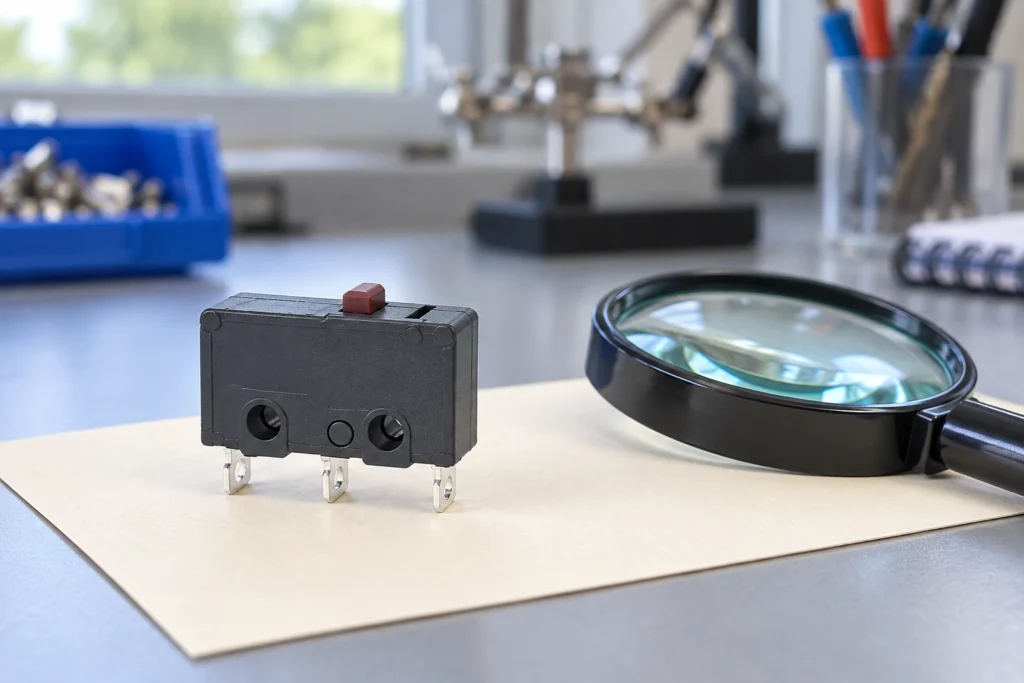
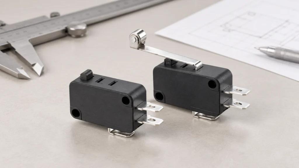
Match the replacement to the machine, not just the switch body A micro switch replacement must match the original contact function, mounting geometry, actuator movement, terminal arrangement and electrical duty. A switch that fits the screw holes can still change the operating point, reverse a control signal or fail prematurely under the connected load. Start with the equipment service instructions and the complete original part number, then compare the proposed replacement against a current drawing and rating sheet. For industrial and appliance assemblies, treat an undocumented substitution as an engineering change requiring validation. This guide explains how to build that comparison without assuming that similar-looking switches are interchangeable. The scope here is a mechanically actuated snap-action component, such as the models in the LEMA micro switch range. It does not provide an approval to replace a machine safety device, a sealed appliance assembly or a manufacturer's proprietary service part. Those cases may require an exact approved component or a complete assembly. Do not bypass an interlock to keep equipment running while a replacement is being sourced. Record the original installation before removing anything Identify the equipment, assembly revision and original switch order code. Photograph the switch from the actuator, mounting and terminal sides, with the circuit isolated. Record the markings exactly, including voltage, current, temperature codes and any separate load-specific ratings. A supplier logo or a partial family name is not enough: terminals, actuators and contact materials can vary within one product family. Record how the actuator contacts the moving mechanism. Note whether a cam touches a roller, a bracket presses a plunger, or a door deflects a lever. Include the normal rest position and the position at which the...

Mehr lesen
Fehlersuche bei Drucktaster-Schaltern: Kontakte, Kabelverlegung und Steuereingänge
Blog LEMA Electric

Fehlersuche bei Drucktaster-Schaltern: Kontakte, Kabelverlegung und Steuereingänge

Die Fehlerbehebung bei Drucktaster-Schaltern funktioniert am besten, wenn Sie vier mögliche Fehler unterscheiden: den Aktuator, die elektrischen Kontakte, die Verkabelung und den Empfangssteuerkreis. Ein normal wirkender Knopf kann dennoch eine schlechte Verbindung aufweisen; ein funktionierender Kontakt kann dennoch ein Signal senden, das die Maschine ignoriert. Beginnen Sie mit der Schaltplanzeichnung und den erwarteten Zuständen bei Ein- und Auslösestellung, isolieren Sie dann die Maschine und untersuchen Sie sie anschließend oder messen Sie den Schalter. Diese Anleitung hilft Herstellern von Industrieanlagen und Wartungsteams, den Fehler zu lokalisieren, ohne anzunehmen, dass jeder Ausfall eine neue Taste erfordert. Die Beispiele beziehen sich auf übliche Steuerungseingänge. Notstopp-, Schutz- und andere Schutzfunktionen erfordern eigene, zugelassene Verfahren und Validierung. Vermeiden Sie niemals das Umgehen von Schutzvorrichtungen, um die Produktion fortzusetzen. Notieren Sie das Symptom, bevor Sie die Kabel bewegen. Notieren Sie genau, was fehlschlägt: keine Reaktion, verzögerte Reaktion, mehrere Reaktionen nach einem Tastendruck, ein Knopf, der nachgedrückt bleibt, oder ein Anzeigefenster, das nicht mehr funktioniert. Notieren Sie außerdem, ob der Fehler nach der Reinigung, nach Vibrationen, beim Start oder nur dann auftritt, wenn die Anlage bereits in Betrieb ist. Diese Informationen helfen, eine beschädigte Komponente von Installationsstress oder einem Problem in einem anderen Teil des Schaltkreises zu unterscheiden. Identifizieren Sie den Schaltbefehlscode, die Zeichnungsrevision, die Anschlussbezeichnungen, die Steuerspannung, die angeschlossene Last und die beabsichtigte Funktion. Ein gedrückter Knopf sollte in seinem ausgewählten Zustand bleiben; ein momentaner Knopf sollte wieder zurückkehren, wenn er losgedrückt wird. Die Verwechslung zwischen den beiden führt zu einer falschen Diagnose. Vergleichen Sie das installierte Gerät mit der genehmigten Stückliste und nicht mit Farbe oder Aussehen. Nutzen Sie den industriellen Schaltknopf-Auswahlführer, um die ursprünglichen Anwendungsanforderungen zu überprüfen. Die Fehlerbehebung sollte diese Anforderungen bestätigen und nicht sie stillschweigend verändern. Energie isolieren, bevor mechanische oder Kontinuitätsprüfungen durchgeführt werden...

Mehr lesen
So testen Sie einen Fußschalter: Isolierte Kontakte und Kabelprüfung
Blog LEMA Electric

So testen Sie einen Fußschalter: Isolierte Kontakte und Kabelprüfung

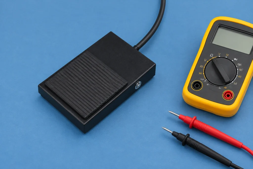
Um einen Fußschalter zu testen, zu ermitteln, welche Funktion er tatsächlich erfüllen soll, ihn sicher von der Ausrüstung zu isolieren und zu trennen und die angegebene Kontaktpaarung sowohl in der freigegebenen als auch in der betätigten Position zu überprüfen. Ein Multimeter kann einen gewöhnlichen mechanischen Schalter auf einen offenen Stromkreis oder eine unzureichende Verbindung prüfen. Es kann jedoch keine Lastbestimmung für einen Pedal, keine Sicherheitszulassung oder die Eignung für eine bestimmte Maschine feststellen. Diese Anleitung behandelt eine reproduzierbare Prüfprotokollierung für industrielle Fußschalter, einschließlich des Pedals, des Kabels und des Steckverbinders, damit Sie eine Schaltfehlererkennung von einem Problem mit dem Kabel oder der Steuerung unterscheiden können. Diese Methode sollte nicht ungeändert auf elektronische, variablere Geschwindigkeits-, medizinische oder sicherheitsgerichtete Fußschalter angewendet werden. Ihre Schaltkreise und Überprüfungsvorgaben können unterschiedlich sein. Folgen Sie der genauen Dokumentation zu Geräten und Pedalen. Identifizieren Sie das Gerät, bevor Sie eine Prüfung auswählen. Ein Fußschalter kann eine einfache Kontakteinheit sein, ein Potentiometer, ein elektronischer Sensor oder eine Mehrstufige Steuerung. Einige Pedalaggregate verfügen über mehrere unabhängige Kontakte. Andere senden ein kodiertes Signal an einen Steuerungssystem. Die Prüfung jedes einzelnen Verbindungsteils wie eine einfache Kontaktprüfung kann verlockende Ergebnisse liefern oder eine elektronische Einheit beschädigen. Lesen Sie die Bestellnummer und das Terminaldiagramm. Notieren Sie, ob die Aktion kurzzeitig oder dauerhaft erfolgt, ob der angestrebte Kontakt normal geöffnet oder normal geschlossen ist und ob der Stecker zusätzliche Schaltungen enthält. Verstehen Sie die Funktion nicht anhand der Form des Steckers, der Drahtfarben oder des Erscheinungsbilds eines ähnlichen Pedals. Die entsprechende Zeichnung sollte die jeweilige Testnummer beschreiben. Die Auswahlhilfe für industrielle Fußschalter erklärt die weiteren Spezifikationsfragen. Diese Testanleitung konzentriert sich auf die Suche nach einer bestehenden Störung, ohne diese Anforderungen zu ändern. Bereiten Sie eine isolierte, kontrollierte Prüfung vor. Folgen Sie den Energiekontrollverfahren des Standorts und überprüfen Sie die Sicherheit...

Mehr lesen
Fußschalter für Pumpensteuerung: Funktionsweise, Schnittstellen und Checkliste für OEM-Anwendungen
Blog LEMA Electric

Fußschalter für Pumpensteuerung: Funktionsweise, Schnittstellen und Checkliste für OEM-Anwendungen

Ein Fußschalter für eine Pumpe sollte normalerweise im Rahmen des Steuergeräts der Pumpe ausgewählt werden: die erforderliche Pedalbetätigung festlegen, die zugehörige Eingabeeinheit oder Schaltvorrichtung identifizieren und die vollständige elektrische Funktion überprüfen, bevor eine Last angeschlossen wird. Ein Momentenpedal kann während des Betätigens den Pumpvorgang anfordern; ein verbleibender Pedalbetätigung kann einen kontinuierlichen Betrieb anfordern. Sofern diese beiden Vorgänge nicht automatisch zu sicheren Stoppen, präziser Dosierung oder Schutz vor unerwartetem Neustart führen, ist dies nicht empfehlenswert. Diese Anleitung bietet Ausrüstungsbauern eine praktische Spezifikation und eine Überprüfungskontrollliste für elektrische Fußschalter, die bei Pumpenoperationen eingesetzt werden. Sie bezieht sich auf eine elektrische Steuerung, nicht auf einen pedalbetätigten mechanischen Pumpen oder ein pneumatisches Ventil. Ein gewöhnlicher Industrie-Pedal muss nicht als geeignet für medizinische Anwendungen, gefährliche Flüssigkeiten oder Sicherheitsfunktionen ohne die entsprechende Systembewertung angesehen werden. Beschreiben Sie die Pumpaufgabe, bevor Sie den Fußschalter auswählen. Braucht der Bediener beide Hände, um einen Behälter zu positionieren, eine Schlaufe zu halten oder eine Anordnung zu justieren? Wurde der Befehl dazu bestimmt, die Pumpe kontinuierlich zu betreiben, einen zeitgesteuerten Zyklus anzufordern oder einen Vorgang nur zu erlauben, solange der Fußpedal gedrückt wird? Dies sind verschiedene Steuerfunktionen. Ein gleiches physikalisches Pedal kann ein sehr unterschiedliches Maschinenverhalten erzeugen, abhängig vom Empfangsnetzwerk. Notieren Sie die Flüssigkeits-, Pumpen-Typen, die Position und die Folgen eines unbeabsichtigten Befehls. Berücksichtigen Sie dabei die Druck- und Bewegungsgefahr, die Risiko von Spritzern, die Nähe zu beweglichen Geräten und die Arbeitsposition des Bedieners. Ein Befehl ohne Hände kann praktisch sein, wenn gleichzeitig ein neues Risiko eines versehentlichen Bedienens eingeleitet wird. Entscheiden Sie, wie die gesamte Maschine diese Gefahr verhindert, bevor Sie die Farbe oder den Gehäusematerial der Pumpe festlegen. Die Auswahlhilfe für industrielle Fußschalter bietet den umfassenderen Rahmen für die Komponentenauswahl...

Mehr lesen
Typen von Limit-Schalterköpfen und einstellbare Positionen des Aktuators
Blog LEMA Electric

Typen von Limit-Schalterköpfen und einstellbare Positionen des Aktuators

Für die Zielbewegung, die zulässige Anfahrrichtung und den Betriebsbereich der jeweiligen Schalterfamilie sollten die entsprechenden Schaltkopftypen ausgewählt werden. Rollenhebel, Stößel, Stäbe und andere Aktuatorformen sind nicht einfach deshalb austauschbar, weil sie die Position erkennen. Einige Konstruktionen ermöglichen die Umpositionierung eines Schaltkopfes unter Verwendung eines festgelegten Verfahrens; andere nicht. Prüfen Sie die vollständige Kombination aus Schaltkopf und Gehäuse, die Ausrichtungsoptionen und die Anweisungen vor dem Wechsel eines bereits installierten Schalters. Diese Anleitung konzentriert sich auf die Auswahl und Ausrichtung der Schaltköpfe für mechanische Positionsschalter. Sie ergänzt die ausführlichen Informationen zu Aktuatoren und Montageanleitungen und dient nicht als allgemeine Anleitung zur Rotation eines Schaltkopfes. Die Bilder der LEMA LZ1-Schalter sind die tatsächliche Referenz für das Produkt; ihr äußerer Erscheinungsbild beweist nicht, dass sie auch mit anderen Serien kompatibel sind. Trennen Sie den Schaltkopf von der gesamten Schaltvorrichtung: Das Gehäuse, die Kontaktanordnung, der Schaltkopf, der Aktuator und die Montage. Ein Ersatzkopf muss mit der entsprechenden Familie und der zugelassenen Kombination übereinstimmen. Ähnliche Schraubenmuster oder Gehäuseformen beweisen nicht, dass die interne Funktionsbeziehung, die Abdichtung oder die Bewegung korrekt sind. Bestellen und die gesamte identifizierte Konstruktion prüfen. Die Codezeichen für Gehäuse und Kopf notieren, sofern sie vom Hersteller zur Verfügung gestellt werden. Wenn der Kopf nicht separat angeboten wird oder keine zugelassene Austauschinformationen vorliegen, gilt er nicht als Ersatzteil. Bitte fordern Sie stattdessen die vollständige Schaltoption an. So wird vermieden, eine physisch anbringbare Kopfform zu ersetzen, die die elektrische oder mechanische Funktion ohne eine etablierte Akzeptanzgrundlage verändert. Beschreiben Sie den Zielansatz in drei Dimensionen. Identifizieren Sie den Ort, an dem das bewegliche Ziel den Aktuator berührt und wie es sich annäht, durchläuft und verlässt. Ein Rollenhebel passt zu einem Kurvenprofil, während ein Kolben eine kontrollierte Druckrichtung annehmen kann. Ein Stab oder ein flexibler Aktuator kann Bewegungen über...

Mehr lesen