
Limit switch cable shielding can help control interference, but it should follow a diagnosis of the complete switch-to-controller circuit. A false PLC transition may come from contact bounce, unstable actuation, a loose connection, incorrect input logic or electrical noise coupled into the cable. Identify the actual cause before changing shield connections. The correct cable route and termination depend on the controller instructions, the installation’s bonding arrangement and the interference being addressed. There is no universal rule that every limit-switch shield must be connected at exactly one end.
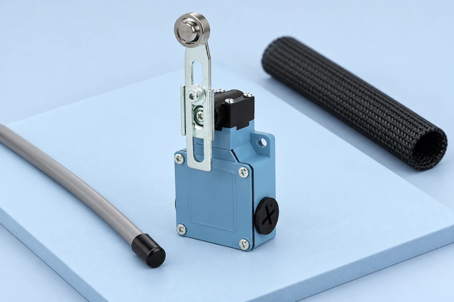
Das LEMA LZ1 mechanical limit switch is the product example here. Its enclosure and actuator do not define the shield arrangement of an external cable or prove immunity of a complete PLC installation. The photographs show the intact switch beside separate cable-planning items, with no approved wiring arrangement implied. Use the exact switch terminal record and controller manual when preparing the circuit.
Establish what the PLC is actually seeing
Write down the unwanted event precisely. Note whether it occurs during switch actuation, while the mechanism is stationary, when a motor starts or during another machine action. Distinguish the PLC’s raw input indication from a program condition or a displayed alarm. These observations help determine whether the problem belongs to the physical signal path or to the way the signal is interpreted.
Beginnen Sie mit dem limit switch PLC wiring guide to confirm the intended contact path and input arrangement. Check the actual terminal identities, supply reference and selected input channel against the drawing. A wiring error should not be hidden by adding shielding or software delays. Record the original configuration so any later change can be assessed against a known starting point.
Separate mechanical bounce from cable pickup
A mechanical contact can make several short transitions during actuation. That is different from interference arriving through or around a long cable while the actuator is stationary. Timing alone does not prove the cause, but it provides a useful starting point for a controlled investigation. Compare the signal with the physical motion and with other equipment events rather than diagnosing from a single input LED flicker.
Das contact bounce guide explains intrinsic switching transitions. If the event instead correlates with a drive, solenoid or contactor elsewhere in the installation, investigate the surrounding electrical environment as well. More than one mechanism can be present. Do not assume that replacing the switch or extending an input filter has resolved every cause merely because one symptom becomes less visible.
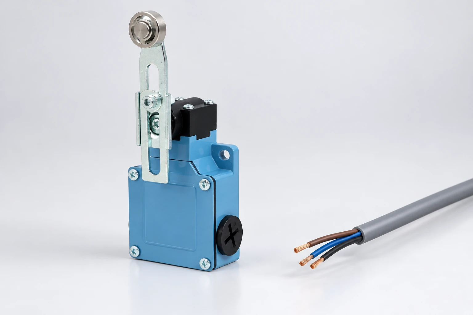
Map the entire signal and return route
A cable contains a circuit, not just a signal conductor. Identify the outgoing and return conductors, the input reference, any intermediate terminals and each shield segment. Mark where the cable enters cabinets, changes route or passes equipment with substantial switching activity. Include junction boxes and maintenance connectors that may not appear in a simplified schematic.
NI’s field-wiring and noise guidance explains coupling mechanisms and the relationship between cabling, shielding and measurement configuration. Its examples concern analog measurement systems; use them to understand the principles, not as a substitute for a particular PLC’s digital-input instructions. Keep controller-specific limits and grounding requirements tied to the actual hardware documentation.
Review routing before adding another shield connection
Compare the signal route with power cables and switching equipment. Ask whether the installation follows the separation and crossing guidance supplied for the controller, drive and associated equipment. A photograph of the cabinet can help document the route, but it should be linked to the drawing and observations. Do not invent a universal separation distance when the relevant equipment instructions have not been reviewed.
Also check mechanical cable condition. A crushed section, loose termination or strained entry can create intermittent behavior that resembles an interference problem. The limit switch troubleshooting guide helps organize those checks. Establish whether the circuit is mechanically sound before using a shielding change to compensate for an unidentified connection fault.
Use a diagnostic table to choose the next observation
| Observed behavior | Question to investigate | Zu sammelnde Beweismittel |
|---|---|---|
| Transitions during actuation | Is contact bounce or unstable motion involved? | Signal timing linked to the physical movement |
| Transitions with a stationary actuator | Is pickup, connection instability or supply disturbance present? | Repeatable correlation with equipment events |
| Intermittence during cable movement | Is an entry or connection mechanically unstable? | Isolated inspection and controlled mechanical checks |
| Change after shield modification | Which circuit or bonding assumption changed? | Exact before-and-after configuration and repeated trials |
| Quiet input after filtering | Is required response timing still satisfied? | Reviewed settings and representative functional verification |
These observations guide investigation; they are not conclusive fault identifications. For example, a transition during motor startup could result from several supply, reference or coupling problems. Collect evidence that distinguishes them. Where timing or waveform measurements are required, use suitable isolated measurement methods and qualified personnel familiar with the equipment’s electrical conditions.
Keep each trial limited and documented. Change one relevant feature, record the exact configuration and repeat the operating condition that produced the symptom. A successful quiet cycle is useful but may not represent the full machine environment. Define a representative verification sequence before declaring that a revised cable arrangement has solved an intermittent problem.
Keep protective bonding separate from a signal return
Protective bonding, signal reference and cable shielding have related but distinct purposes. Do not disconnect a protective connection as an informal experiment to remove noise. Follow the equipment’s safety procedures and use a qualified design review when the bonding arrangement is uncertain. A quieter input is not evidence that an electrically unsafe modification is acceptable.
NASA’s electrical bonding standard is a reference for the importance of deliberate bonding in its aerospace scope. It is not a certification standard for the illustrated LEMA switch or a ready-made PLC installation recipe. In a factory machine, the applicable equipment requirements and manufacturer instructions determine the actual protective and functional bonding arrangement.
Do not apply a one-end rule without its assumptions
Shield termination decisions depend on the installation and the interference frequencies of concern. Ground-potential differences and high-frequency bonding behavior can lead to different design requirements. That is why a rule repeated without context can produce conflicting advice. Ask which equipment instruction and engineering assumptions justify the proposed connection at each end.
Document the physical termination method as well as the point named on the drawing. A shield that is present in the cable but not continued or terminated as intended may not behave as the designer expects. Check junctions, connector transitions and entry arrangements against the approved method. Do not treat the shield as a spare signal conductor or assume that an enclosure screw is automatically the correct termination point.
Evaluate filtering without hiding a timing problem
A controller input filter can affect how short transitions are recognized. Review the manufacturer’s input settings and the machine’s required response before changing them. The purpose is to support a valid signal, not to conceal unexplained changes. A setting that suppresses an unwanted pulse can also delay recognition of a genuine event, so its effect belongs in the functional review.
Der akzeptierte Einstellwert und der Grund dafür sollten mit der Hardwarekonfiguration dokumentiert werden. Wenn das Signal an einer Sicherheitsfunktion beteiligt ist, verwenden Sie das entsprechende Sicherheits-Systemdesign und Validierungsprozess anstelle dieses allgemeinen Diagnoseratgebers. Ein gewöhnlicher mechanischer Schalter und eine ruhige Eingangsspur stellen nicht die Diagnosesicherheit oder Leistung eines Sicherheitskreises dar.
Geben Sie eine Kabelbaugruppe an, die gewartet werden kann
Eine Beschaffungsanfrage sollte die vom überprüften Design erforderliche Kabelkonstruktion, den Verlauf, die Anschlussanordnung und die Eingangskomponenten identifizieren. Fügen Sie die beabsichtigte Länge und den Anschlussplan bei. Bitten Sie den Lieferanten, zu unterscheiden, was er bereitstellt, und was vom Gerätebauer installiert werden muss. Ein unverbundenes Kabel neben einem Produkt ist kein Nachweis für eine genehmigte abgeschirmte Baugruppe.
Für Wartungszwecke bewahren Sie eine identifizierbare Ersatzspezifikation und Anweisungen zur Wiederherstellung der überprüften Anordnung auf. Definieren Sie, welche Prüfungen nach einem Austausch von Kabel, Kabelverschraubung oder Steuerung erforderlich sind. Ein nützliches Abschlussdokument umfasst das ursprüngliche Symptom, die gesammelten Beweise, die akzeptierte Korrektur und die Überprüfungsbedingungen. Dies verhindert, dass das gleiche intermittierende Problem nach jedem Servicebesuch von Anfang an untersucht wird.
Weiterführendes Lernen: Erdungs- und Abschirmungsprinzipien
Das folgende unabhängige Physik-Video erklärt Erdungs- und Abschirmungskonzepte. Es unterstützt das Verständnis des elektrischen Verhaltens, während das Steuerungs-Handbuch und das Installationsdesign die tatsächlichen Maschineneinstellungen regeln. Es zeigt nicht die Immunität oder genehmigte Verkabelung des gezeigten LEMA-Produkts.
Physik-Videos von Eugene Khutoryansky: Erdung und Abschirmung elektrischer Schaltungen
Sehen Sie sich das Video zur Erdung und Abschirmung elektrischer Schaltungen an.
Häufig gestellte Fragen
Muss jedes Schaltkontaktkabel der Endschalter nur an einem Ende geerdet werden?
Es gilt keine universelle Beendungsregel für jede Installation. Befolgen Sie die Anweisungen des Steuergeräts und der Ausrüstung und bewerten Sie die Erdungsverbindung sowie die Störungsbedingungen. Dokumentieren Sie die Annahmen, die der gewählten Methode zugrunde liegen.
Wird Abschirmung den mechanischen Kontaktprellen entfernen?
Abschirmung bezieht sich auf die elektrische Kopplung und nicht auf den Schaltkontaktmechanismus. Unterscheiden Sie Übergänge, die mit der Betätigung verbunden sind, von Störungen an anderer Stelle im Stromkreis, bevor Sie eine Korrektur auswählen.
Kann ich die Schutzerdung trennen, um Störgeräusche zu untersuchen?
Verwenden Sie nicht die Entfernung einer Schutzverbindung als informativen Diagnoseschritt. Befolgen Sie sichere Geräteverfahren und lassen Sie unsichere Erdungsverbindungen von einem qualifizierten Fachmann überprüfen. Ein leiseren Signal beweist nicht, dass die Modifikation sicher ist.
Etabliert eine Gehäuseklassifizierung LZ1 die Störfestigkeit des PLC?
Nein. Das Schaltgehäuse und die komplette Signalanlage beantworten unterschiedliche Fragen. Überprüfen Sie das Kabel, den Controller-Eingang, Referenzen, Wegführung und Anschlüsse anhand der tatsächlichen Gerätdokumentation und der Prüfergebnisse.