
Micro switch contact bounce is a brief series of electrical transitions around a single mechanical switching event. A snap-action mechanism makes the change decisive, but it does not guarantee that a fast controller sees exactly one edge. For a roller-lever or plunger micro switch on an OEM machine, investigate both the contact signal and the motion that operates it. Then accept a stable state or a qualified event at the controller. A debounce delay alone cannot correct a cam that repeatedly crosses the operating point, an overloaded contact, or a damaged harness.
This guide focuses on micro switches operated by mechanisms: rollers following cams, plungers touched by moving parts, and small levers detecting position. It addresses event validation, not a generic replacement procedure or a fixed debounce circuit. Start with the actual switch drawing, the controller input specification and a record of the machine movement. The aim is to reject unintended transitions without hiding a genuine position change.
Separate one switching event from repeated mechanical actuation
A useful first question is whether the actuator makes one controlled pass through the switch point. Contact bounce occurs during contact settling. Mechanical re-actuation occurs when the moving part repeatedly operates and releases the switch. Both can produce multiple edges, but they require different corrections. A loose roller bracket, oscillating linkage or cam dwelling near the release point can keep creating valid mechanical changes long after the first contact transition.
Das University of Washington Makeability Lab lesson on debouncing explains how moving electrical contacts can oscillate before settling. Use that principle to interpret a short transition cluster, while separately checking whether the machine motion continues to cross the switching boundary. Do not label every noisy trace as a defective micro switch.
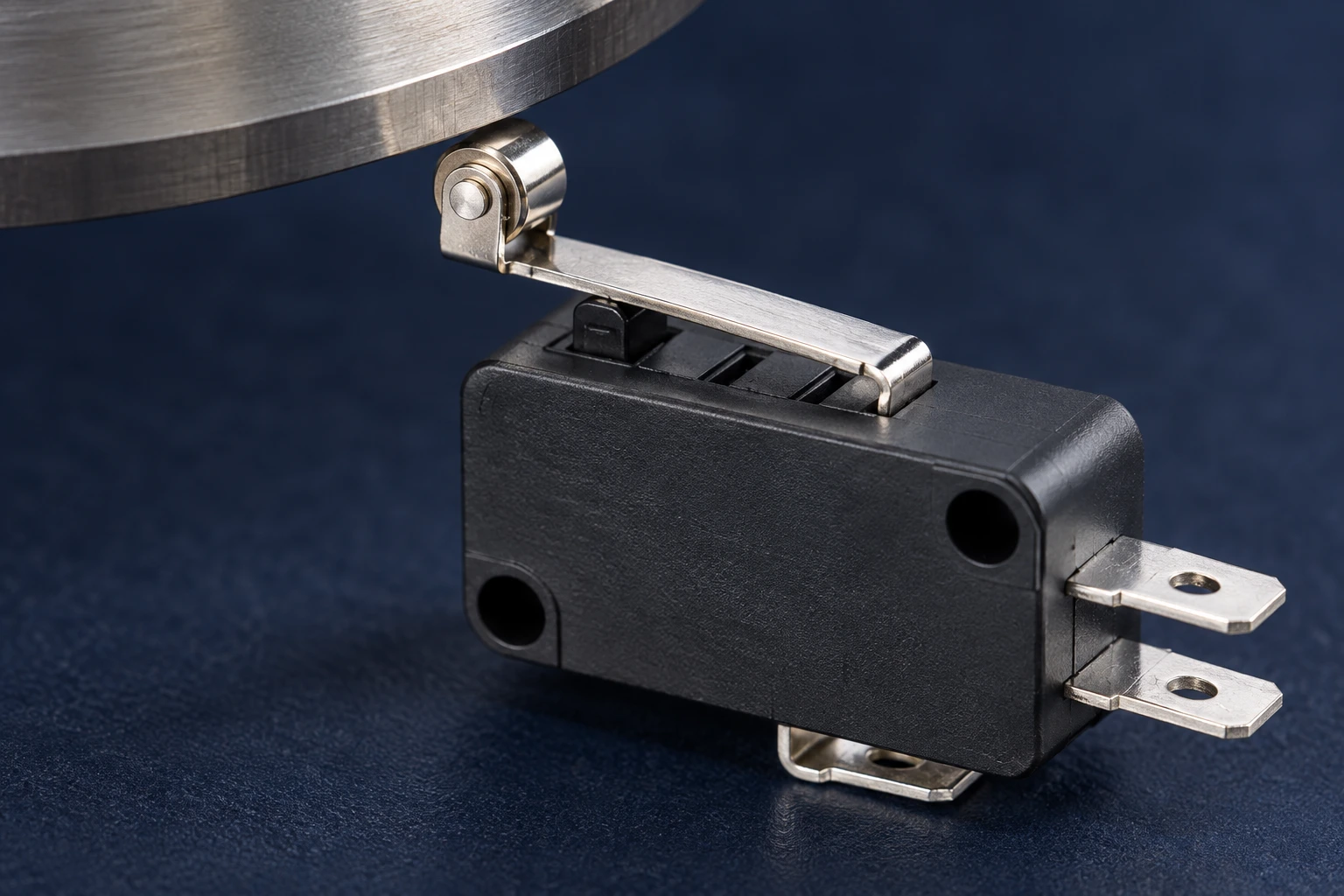
On a stopped, safely isolated mechanism, observe the roller or plunger through its intended travel. Record the direction of movement, how the actuator is contacted, and whether the bracket moves. Consult the model drawing for permitted travel. Do not use the switch body as a mechanical end stop unless the exact installation instructions explicitly allow it. For the geometry terms, see the separate micro switch travel guide; verify the linked model and permitted movement before altering a fixture.
Decide what the controller actually needs to know
A position indication, a product counter and an operator command have different acceptance criteria. A position input often needs a reliable held state. A counter needs one event per passing object. A sequence controller may need both an operation event and a release event. Writing these requirements before choosing a filter prevents a technically neat debounce scheme from changing the machine’s intended behavior.
For example, a cam that holds the switch operated for most of a revolution can tolerate a different qualification strategy from a brief passing tab. The relevant question is whether the intended pulse remains long enough to be recognized after input filtering and program execution. A filter that removes duplicates but also suppresses short legitimate pulses has not solved the problem.
| Observed behavior | First evidence to collect | Appropriate next decision |
|---|---|---|
| A short cluster of transitions at one operation | Capture the input waveform and the associated actuator pass. | Qualify a stable state or a single event using measured settling behavior. |
| Repeated operation and release while the roller dwells | Check cam position, bracket movement and travel relative to the model drawing. | Correct the mechanical movement before increasing an electronic delay. |
| Transitions with the actuator stationary | Compare the switch signal with the controller input and nearby equipment switching. | Investigate the harness, reference connection or electrical interference. |
| Missing events after a filter change | Measure the shortest intended pulse and the complete input recognition path. | Revise qualification timing without accepting duplicate counts. |
| Contact remains open or closed after movement | Perform an isolated contact check and inspect the mechanism. | Treat this as a persistent fault; debounce cannot restore the missing state. |
The table is a diagnostic decision aid, not a list of verified faults in any particular LEMA model. It intentionally gives no universal bounce time, input voltage or acceptance resistance. Those values depend on the exact switch, input circuit and application evidence.
Capture the input without changing the behavior being investigated
Use a qualified person and suitable equipment to investigate energized circuits. A bench test on an isolated, low-energy input arrangement is different from probing installed mains equipment. Do not attach an oscilloscope ground clip to an unknown reference or assume that an ordinary grounded instrument can safely measure every industrial control circuit. Follow the instrument and equipment instructions.
Record where the signal is measured: at the contact terminals, at a connector or at the controller input. These points are not interchangeable. A clean contact-level transition with a noisy controller trace suggests that the interconnection or input environment contributes to the problem. When practical and safe, compare the electrical trace with a motion record so an actual second actuator pass is not confused with contact settling.
Save several operation and release events at the mechanism’s expected speeds. Include the conditions most likely to reveal a problem, such as a slow approach, a light touch, vibration or a rapidly passing target. Do not infer a guaranteed maximum from one favorable oscilloscope screenshot. Record the input supply, interface arrangement, switch order code and test conditions so another engineer can repeat the observation.
Qualify states and events as separate requirements
For a held-state input, one practical approach is to change the accepted state only after the sampled input has remained stable for a defined qualification period. When the raw state changes again, restart qualification. The accepted state therefore follows confirmed operation and confirmed release rather than every edge. The period should come from measured behavior and the machine’s allowable response time.
For a counter, also define when the next event becomes eligible. Simply ignoring edges for a fixed interval can allow a later bounce to be counted or suppress a real second product. A clearly defined re-arm condition, usually associated with a qualified release and the process sequence, makes the event rule explicit. Test two closely spaced legitimate targets as well as one target that produces multiple transitions.
Northwestern University’s switch debouncing notes discuss why fast logic can respond to mechanical contact transitions and describe a hardware approach. Hardware can condition the electrical input before software sees it; software can qualify how the application interprets that input. Neither option is automatically sufficient for every mechanism.
A controller’s built-in input filter may already provide part of the qualification. Read its documentation before adding another delay. Account for the complete path from the physical movement to the program’s accepted state. Changes to filtering, scan behavior and edge detection can all affect the time at which a machine recognizes a position. Keep any safety-related response analysis under the equipment designer’s validated process.
Check what debounce cannot fix
Debounce does not increase contact load capacity. A micro switch used to command a controller must still match the input’s electrical requirements. A switch used to interrupt a load must match the actual load category and switching duty. Do not use a signal filter to hide contact damage caused by an unsuitable electrical duty.
Debounce also does not correct an actuator that is permanently pressed too far, a broken spring, contamination in an unprotected installation or a loose terminal. If the switch cannot reliably establish both required contact states in an isolated test, stop treating the problem as a transient input-processing issue. Preserve the failed part and the installation evidence for investigation.
The existing toggle switch bounce guide discusses general debounce choices for manually selected states. Here the distinguishing requirement is the relationship between the micro switch and the moving mechanism. The micro switch replacement guide covers form, fit and function when a damaged component needs replacing.
Release an OEM mechanism with a repeatable acceptance record
Define the acceptance record before testing the final sample. For a position input, state which movement must be detected and the latest acceptable recognition point. For a counting input, state the expected event count for a known sequence. Include operation, release and the shortest valid pulse. Re-run the sequence after changes to the cam, bracket, switch variant, cable or controller filter.
Keep raw waveform evidence separately from the accepted software event log. The two records answer different questions: what the electrical interface produced, and what the machine decided. If a duplicate event disappears only because the program now ignores a genuine release, the release test will expose it. Also test power-up and return-to-service behavior under the equipment’s normal commissioning procedure.
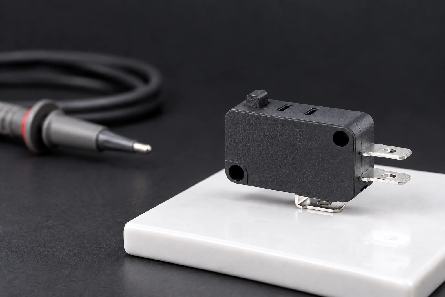
For a LEMA inquiry, provide the mechanism sketch, actuator style, contact function, terminal format, input interface and environment. The KW7 micro switch product family offers a starting point for a model-specific discussion; the illustrations here show the external plunger and roller-lever forms, not a verified electrical circuit or guaranteed bounce specification. Obtain the exact order-code drawing and test requirements before approval.
For the broader selection context, use the Auswahlleitfaden für industrielle Mikroschalter to organize the input requirements before requesting samples.
Video: understand why contacts bounce
All About Circuits provides an educational demonstration of switch bounce. Watch it to understand transient contact behavior, then relate the principle to the actual roller or plunger motion. The video does not specify the bounce time of a LEMA model or validate a machine’s input filter.
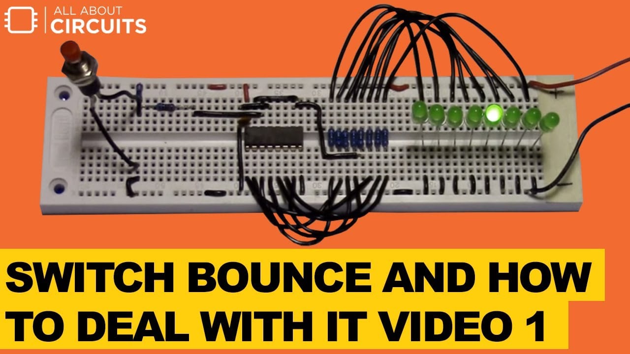
Watch the educational switch bounce video on YouTube.
Häufig gestellte Fragen
Does snap action eliminate micro switch contact bounce?
No. Snap action makes the mechanical change decisive, but a fast input can still detect transient contact transitions. Verify the actual input behavior and the mechanism movement.
Can I use one debounce time for every micro switch?
Do not assume a universal value. Select qualification from observed switching behavior, valid pulse duration and the controller’s response requirements, then validate the complete application.
Why does a roller micro switch keep changing state?
A cam or linkage may repeatedly cross the operating and release points. Check mechanical movement, mounting stability and permitted travel before treating repeated actuation as contact bounce.
Can debounce repair a stuck contact?
No. A persistently open or closed contact requires fault investigation. Input qualification cannot restore a contact state that the mechanism or electrical contact no longer produces.