
A toggle switch used for a low-level signal needs evidence for the actual electronic input, not only a high-current power rating. The input voltage and current, contact behavior, permitted signal errors, environment and operating sequence must all be considered. An ordinary continuity beeper can identify a static path but cannot establish reliable service on every dry-circuit or low-current interface. Ask for applicable minimum-load information and validate the complete selector circuit before release.
The LEMA LT2210C product is the visible toggle reference in this article. Its appearance or headline power rating does not establish a low-level switching guarantee. The disconnected instruments in the figures illustrate review boundaries, not a tested circuit, recommended pinout or model-specific dry-circuit approval.
Define what low level means in the actual circuit
Describe the signal source and receiver. Record the input voltage, current through the closed contact, thresholds, leakage paths, wiring and the intended response. A logic input, resistive sensing network and analogue measurement path can impose different requirements even when their nominal supply is similar.
Avoid treating “dry circuit” as a universal voltage or current limit. Terminology and test conditions need to be understood in the relevant specification. State the actual values and acceptance criteria for the equipment instead of relying on an undefined label.
The NIST guidance on electric current provides the unit basis. Keep ampere, milliampere and microampere values distinct when preparing the review; a unit mistake can conceal how little current an electronic input actually supplies.
Separate maximum load capacity from minimum-load suitability
A power rating addresses operation under stated load conditions. It does not automatically answer whether the contact will provide the required behavior at a much smaller signal level. Likewise, a switch that works in a low-level prototype has not thereby demonstrated suitability for its maximum power duty.
Obtain the exact contact variant and applicable documentation. Ask which minimum-load or low-level conditions the supplier supports and what test evidence applies. Do not transfer a value from another switch family or infer contact material and finish from the external housing.
The heavy-duty toggle rating guide addresses the power-load question. Keep that selection evidence separate from the low-level selector interface discussed here; neither question is answered solely by the external size of the switch.
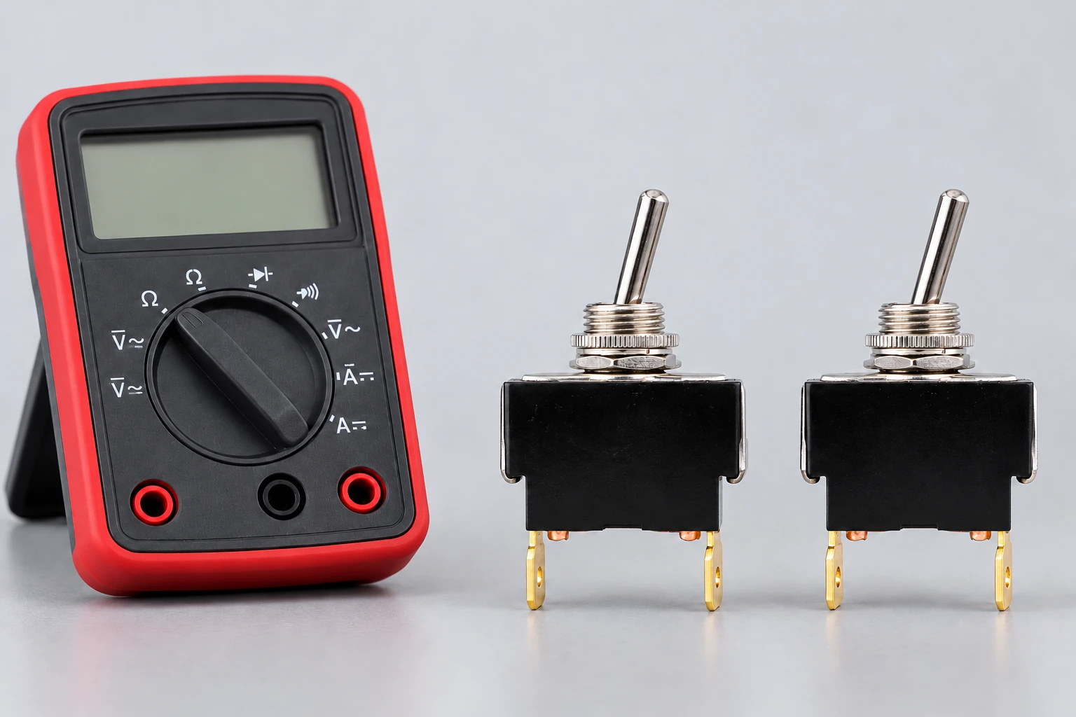
Define the closed-state electrical requirement
The receiver may require more than a simple contact-state indication. Determine how closed-path resistance, variation or intermittent behavior would affect the signal. Include the wiring and connector interfaces in that assessment rather than attributing every change to the switch contacts.
Select a measurement method suitable for the required range and circuit boundary. A two-wire resistance reading can include leads and connections. A continuity indicator may use its own threshold and test current, which may differ from the equipment input.
Do not quote a universal acceptable resistance from this guide. The application requirement, component specification and measurement method must establish the criterion. Record the location, current, instrument and environmental condition associated with the result.
Define the open-state requirement as well
Review what the input sees when the selector is open or between positions. Pull-up or pull-down arrangements, leakage, interference and the controller’s interpretation can matter. A floating input or an incorrect common connection can create a system symptom even when the mechanical switch operates normally.
Identify the permitted states during transfer and after settling. Where the circuit needs a defined break-before-make sequence or other timing behavior, obtain the evidence for the exact variant. Do not infer dynamic transfer from the lever position or a static terminal map.
The transfer-timing guide addresses that separate question. Keep its acceptance criteria alongside the low-level input requirements without treating either one as proof of the other.
Keep bounce and sustained instability distinct
Mechanical contacts can produce transitions during operation that the receiver must interpret appropriately. Define which event is meaningful to the equipment and what filtering is permitted. A maintained selector usually requires a stable final state, while an edge-driven command may also depend on how transitions are counted.
The toggle contact-bounce guide covers the transient interpretation. A software filter can reject some unwanted transitions, but it cannot approve an unsuitable contact system, repair a wiring fault or establish acceptable long-term closed-path behavior.
Record the raw signal and the processed controller state where necessary. A display that looks stable may conceal events the controller ignored, and a noisy trace may be caused by the measurement arrangement itself. Use the actual equipment requirement to interpret the observation.
Review contamination and environment without inventing a cure
Identify the exposure relevant to the installed assembly: dust, moisture, residues, cleaning chemicals or other conditions. Do not assume that adding current, spraying cleaner or cycling the switch repeatedly is an approved way to restore a low-level contact.
Preserve suspect samples before cleaning or changing the circuit. Record the original input conditions and the history of the symptom. An intervention that changes surface condition or electrical stress can alter the evidence and may create a different operating condition from the intended one.
Ask the supplier about the supported contact option and environment. A different finish or construction may require a different order code and qualification. Do not promise that an unspecified material change will solve the equipment problem.
| Circuit boundary | Record | Do not substitute |
|---|---|---|
| Closed state | Actual current path and permitted resistance behavior | Continuity-beeper approval for every input |
| Open state | Threshold reference leakage and bias arrangement | An undefined floating input assumption |
| Transition | Meaningful event and permitted filtering | Software delay as a cure for every fault |
| Contact option | Exact variant and supported low-level conditions | Maximum power-current label |
| Validation | Representative circuit environment and sequence | A higher-current test that changes the question |
Use a representative low-level validation plan
Define the candidate, input circuit, wiring, environment, operation sequence and pass criteria. Include startup, long dwell, repeated selection and the transitions that matter to the equipment. Identify whether the test is exploratory, a functional check or part of a longer qualification.
Choose instruments that can observe the relevant state and variation without changing the circuit in a way that invalidates the result. State the measurement loading and resolution. A test source that supplies much more current than the real input can answer a different question.
The HSE electrical-testing guidance explains the need for controlled test arrangements. Low signal level does not remove other hazards in the equipment or justify probing an energized enclosure without the approved procedure.
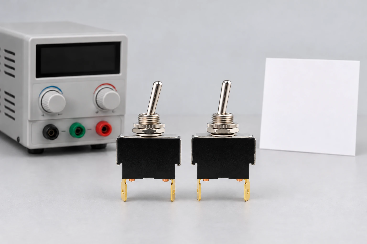
Review the complete selector assembly
The toggle is only one part of the path. Inspect terminals, mating connections, conductor support and the input reference. A mechanically loose connection or a wiring error can defeat a suitable switch. Keep the interface findings separate from internal contact behavior.
Confirm the exact poles, throws and intended terminal mapping before evaluating the signal. Do not use the external lever direction as proof of a particular terminal state. Establish the static mapping with the drawing and an appropriate isolated check.
The micro switch minimum-load article explains the related concept for another product family. It is background rather than approval to copy a micro-switch value onto a toggle switch. Each candidate and circuit need their own evidence.
Make the inquiry specific enough to answer
Send the complete toggle order code, circuit diagram, input voltage and current, thresholds, wiring length, environment and operating sequence. State the observed or permitted signal errors and the required service behavior. Include traces and measurement settings if a problem is being investigated.
Ask for the applicable low-level or minimum-load specification and its conditions. The IEC 61058-1 catalogue identifies general appliance-switch requirements; it does not provide a model-specific low-level rating for the illustrated product.
Use the LEMA inquiry page to discuss the real input interface. A supported decision connects the exact contact option to the circuit requirement, rather than relying on a large current number printed on the housing.
Further learning: interpreting a contact transition
All About Circuits: Switch Bounce and How to Deal with It Video 1. This independent educational video explains switch-contact transitions and debouncing. It supports the section on interpreting events; it does not establish minimum-load performance or approve the illustrated LT2210C circuit.
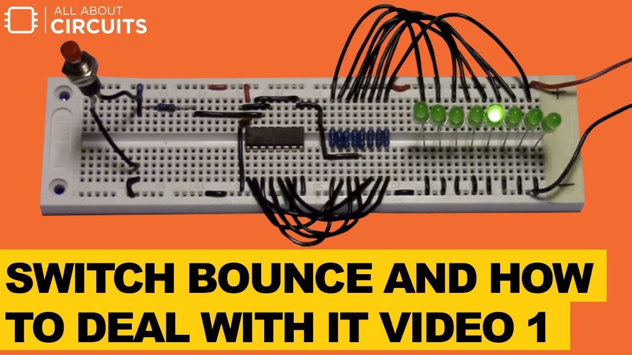
Watch Switch Bounce and How to Deal with It Video 1.
Frequently asked questions
Does a high current rating approve low-level signals?
No. A maximum power-load rating addresses stated conditions and does not automatically establish minimum-load behavior. Obtain the exact contact-option evidence and validate the real input current, thresholds, wiring and operating sequence.
What current should every dry circuit use?
There is no universal value supplied by this guide. Clarify the relevant definition and specification, then state the actual circuit requirements. Do not copy a minimum-load number from a different product family or contact variant.
Can I add current to clean the contacts?
Do not treat that as an approved universal remedy. It changes the electrical stress and may affect evidence or circuit behavior. Preserve suspect samples and obtain the supplier-supported contact option and test conditions for the actual application.
Can filtering prove low-level compatibility?
No. Filtering can change how transitions are interpreted, but it does not qualify contact materials, repair wiring or establish long-term closed-path behavior. Define both the raw electrical requirement and the permitted controller response, then verify each.