
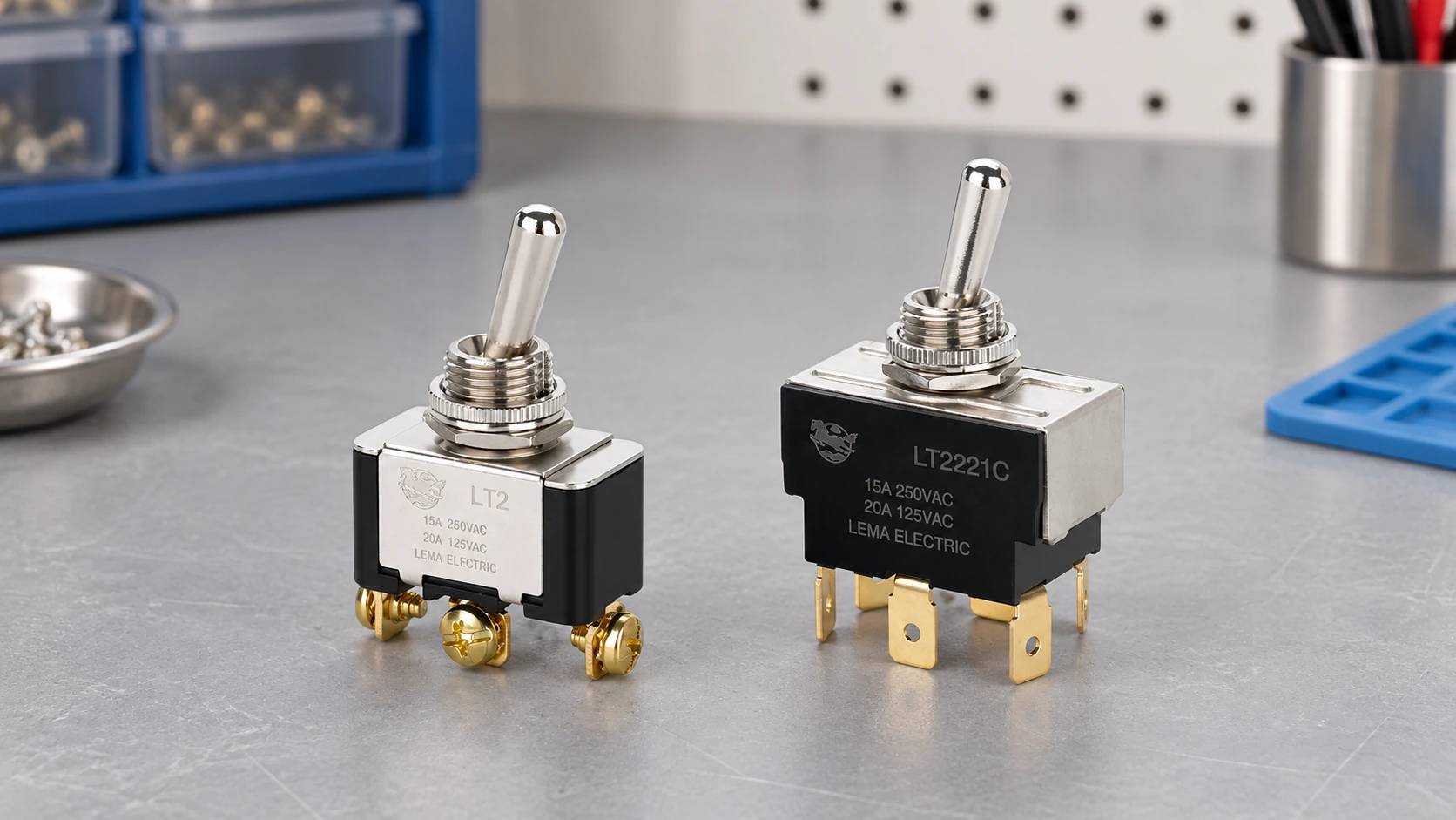
Toggle switch contact bounce is the brief sequence of unwanted make-and-break transitions that can occur as mechanical contacts change state. A person may see one deliberate movement while a fast electronic input detects several edges, which can create duplicate counts, repeated commands or a noisy state transition. Whether bounce matters depends on the receiving circuit and its response time. Confirm behavior at the actual controller input, then use an appropriate hardware or software debounce method; do not assume every toggle switch has the same bounce time.
What happens during contact bounce
A mechanical contact does not always move from open to closed in one perfectly clean edge. The moving parts have mass and elasticity; when contact surfaces meet, they can briefly separate and reconnect before settling. On opening, an edge can also include brief transitions depending on the mechanism and measurement circuit. A receiving input may therefore see a short pulse train where an operator intended one state change.
All About Circuits’ electronics textbook section on contact bounce explains how several transitions can be interpreted as multiple counts by a digital circuit. The University of Texas ECE embedded-systems chapter describes hardware and periodic-sampling approaches, including why the stable interval must be chosen for the actual switch. These sources explain the general mechanism; they do not specify the bounce time or endurance of a particular LEMA model.
Do toggle switches bounce?
Yes, a toggle switch can produce contact bounce. The external lever style does not make the internal contacts immune. A maintained toggle changes to a new mechanical position and remains there, while a momentary toggle returns after release; either type can create transitions at the electronic interface. The exact behavior depends on the contact mechanism, actuation, circuit, measurement bandwidth and sample.
Do not assume that a toggle bounces for a fixed number of milliseconds, or borrow a timing value from an unrelated push button. Texas Instruments notes that physical switches may bounce over short intervals while logic inputs respond much faster, but its SCEA094 application brief is a design example, not a universal specification for every switch. Use the chosen switch’s data where available and measure the real interface when timing is important.
Separate bounce from noise, chatter and contact failure
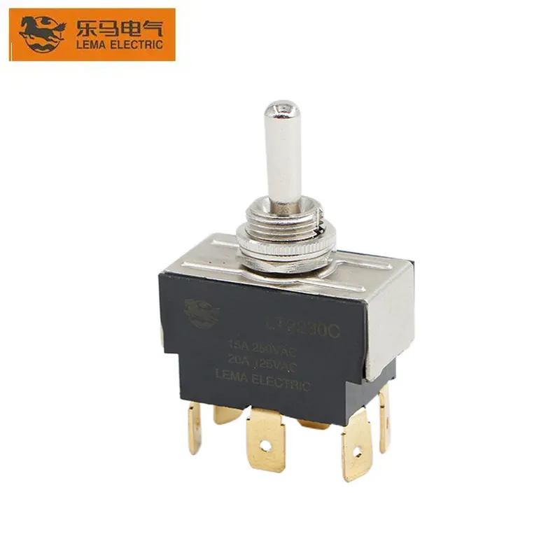
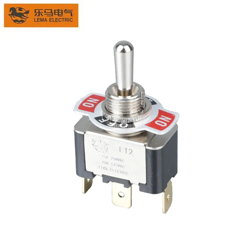
Several symptoms can look like bounce but need different investigations. Electromagnetic interference may add spikes to a long or poorly routed signal wire. A loose terminal can produce intermittent continuity. A switch mechanism that is mechanically unstable may chatter around a threshold, while a controller’s input threshold or filtering may be unsuitable. Worn or contaminated contacts can create high or erratic resistance. Debouncing can suppress short transition sequences at a logic input, but it cannot repair a loose terminal, damaged contact or unsuitable load.
Start with the event pattern and reproduce it using the same circuit, cable, input, ground reference and switching speed as the machine. Check the stable voltage levels as well as the transition. If the signal has large noise spikes, investigate wiring, shielding, grounding and input conditioning. If the contact itself is inconsistent at a safe low-voltage measurement point, inspect the switch and termination. Do not jump straight to a longer software delay; it can hide a fault or make a real input feel unresponsive.
When bounce matters
For a slow lamp or a human-readable indicator, a brief transition may be invisible. A counter, edge-triggered interrupt, PLC fast input, digital clock or control input that responds to every transition may instead register multiple events. The relevant question is not only “how long does the contact bounce?” but “what does this receiver treat as a valid edge?” Input thresholds, scan or sample rate, filtering, polarity and the application response all matter.
For a toggle used as a maintained state selector, the application may care about the final stable position rather than every intermediate edge. A controller can sample the input and accept a state only after it remains unchanged for a defined interval. For an event counter or pulse capture, the logic may need to accept the first transition and ignore subsequent transitions until the signal has settled. Design the behavior around the machine’s required response, including what should happen at startup and if the wire opens or shorts.
Choose a debounce approach that fits the input
Hardware and software methods are both common. An RC network followed by a Schmitt-trigger input can slow a transition and provide hysteresis. A latch can suppress the repeated transition in suitable switch arrangements. A dedicated debouncer can handle the input directly. In software, a state machine can require a stable reading over a selected interval or use a timer-based lockout after the first edge. Each method has limits: analog filters change edge timing, input thresholds vary, and a fixed software delay can miss intentional rapid operations.
National Instruments’ guidance on removing digital-line glitches shows common hardware filtering approaches, while TI’s application brief discusses a Schmitt-trigger-based debounce example. These are circuit design references, not ready-made values for every switch or controller. Select component values and software timing from the input’s electrical limits and observed behavior.
| Observed use case | Possible approach | Validation question |
|---|---|---|
| One slow human-operated state input | Stable-state sampling or input filtering in the controller | Does the final state settle correctly without making operation feel delayed? |
| Fast counter or interrupt input | Hardware conditioning, a timer-driven state machine or a suitable debouncer | Does one actuation produce exactly one accepted event at the fastest expected operation? |
| Long cable with spikes or ground disturbance | Investigate routing and grounding, then add suitable input protection and filtering | Are the extra transitions actually contact bounce, or external interference? |
| Unstable or worn contact | Inspect the termination, switch condition and application duty before filtering | Does the switch meet its specified load and operating conditions? |
Measure the signal at the point the controller receives it
For a low-voltage logic input, capture the signal at the controller-side input using an oscilloscope or logic analyzer appropriate for the voltage and circuit. Observe both the actuation and release edges. Record the switch model, contact arrangement, supply, pull-up or pull-down circuit, cable length, controller input type, probe point and test condition. Compare the raw waveform with the controller’s recognized state. A waveform at the switch terminals can differ from the waveform after a long cable or an input filter.
Test representative samples and repeat the operation enough times to reveal variation; one clean trace is not proof of a guaranteed bounce limit. If temperature, vibration, contact load or actuator speed varies in service, include relevant conditions in the validation plan. The maximum time selected for a debounce filter should be based on observed worst-case behavior plus a justified design margin and should still satisfy the machine’s response-time requirements.
Use proper isolation and rated probes if any part of the circuit is not extra-low voltage. Never connect a grounded bench instrument directly to a mains circuit without an appropriate, qualified measurement method. Debouncing is a signal-conditioning function; it is not electrical isolation, overcurrent protection, arc suppression or a machine-safety function.
Keep signal debounce separate from power switching
A debounce routine can make a controller read a mechanical input more reliably, but it does not increase the electrical rating of a toggle switch. If the switch directly makes or breaks a motor, solenoid or other load, load-specific rating, inrush, arcing, suppression and protective design still apply. A small RC network intended for a logic input should not be placed across a power contact without a design review. Separate the operator input from a higher-energy load using a suitable interface where the machine design calls for it.
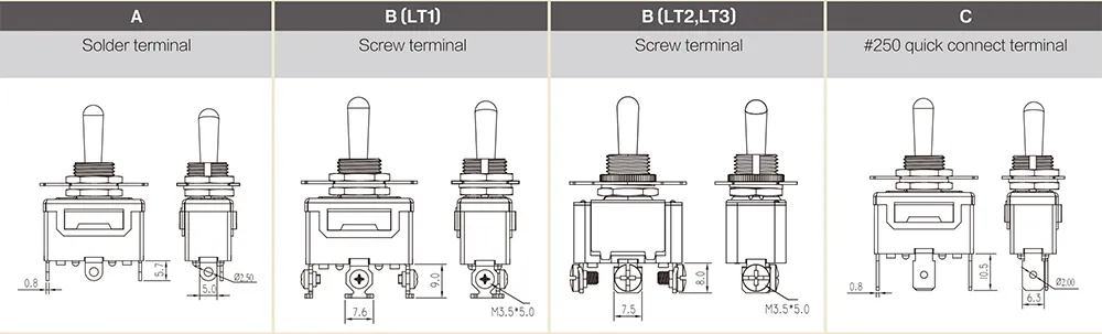
For selection, consult the exact LEMA LT2 product documentation and confirm the full model, contact form, terminals and electrical duty. The product-page image below identifies terminal options; it does not indicate a bounce specification.
Release checklist for an OEM input
- Document whether the toggle is maintained or momentary and which contact transition the controller uses.
- Confirm normal and operated contact states, terminal layout and the exact model drawing.
- Measure the waveform at the receiving input and distinguish contact bounce from external noise or wiring faults.
- Choose hardware or software filtering that meets both noise rejection and response-time requirements.
- Test both actuation and release, representative samples and the expected operating environment.
- Verify that filtering cannot mask a broken wire, short circuit or fault that the machine is required to detect.
- Keep logic debounce separate from power-contact ratings and machine safety functions.
For adjacent design topics, see the toggle-switch mechanism guide for actuator behavior and the toggle-switch terminal-types guide for connection options. The 4-pin toggle wiring guide and 6-pin toggle wiring guide cover circuit identification; follow the exact switch drawing rather than wire color or pin-count assumptions.
Watch a demonstration of switch bounce
The following All About Circuits video demonstrates switch bounce and ways to deal with it. It provides a visual explanation of the signal problem, but does not characterize a LEMA model or replace the measurement and design checks above.
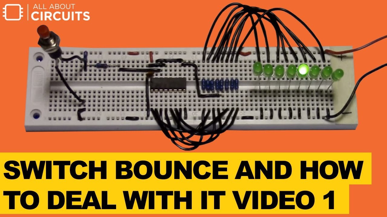
Watch Switch Bounce and How to Deal with It on YouTube.
Frequently asked questions
Does every toggle switch have the same bounce time?
No. Bounce depends on the mechanism, sample, actuation, contact and measurement circuit. Use the exact model’s documentation and validate the actual input when timing matters.
Can software debounce fix electrical noise on a long cable?
It may suppress brief extra transitions, but it does not correct poor routing, grounding, shielding, loose connections or an unsuitable input. Diagnose the signal source before choosing a filter.
Is a 10 ms debounce delay always enough?
No universal interval applies to every switch and system. Select a value from measured or specified behavior and confirm it still meets the application’s response-time requirement.
Does debounce make a toggle switch safe for switching a motor?
No. Debounce conditions a logic signal. It does not change the switch’s load rating, protect contacts or establish that the machine’s safety functions are adequate.