
Limit switch welding spatter protection starts with controlling where hot particles can reach the installed switch and whether accumulated material can obstruct its motion. An ingress rating alone does not establish resistance to molten metal, repeated radiant heat or deposits around a roller and pivot. For equipment buyers, the practical requirement is a documented arrangement that preserves the intended actuation while allowing safe inspection and maintenance. Select the exact switch, placement and shielding together; then verify the assembly against the actual process rather than assuming that a robust housing makes every welding-cell location acceptable.
Identify the exposure before choosing a shield
Describe the welding process, workpiece positions, fixture movement and all operating modes. A switch outside the direct deposition path may still collect particles reflected from another surface. A maintenance position can create an exposure that is absent during automatic production. Include loading, unloading, setup and recovery operations in the review. The objective is to understand where deposits can arrive, not to establish a universal safe distance from a welding arc.
Observe the process through an authorized assessment conducted with the machine’s protective measures in place. Record the affected surfaces and deposit locations without approaching hazardous moving or energized equipment. The responsible team should distinguish solid spatter from grinding debris, dust, paint, liquid coolant and general dirt. These contaminants may require different controls, and a measure effective for one should not be treated as evidence for another.
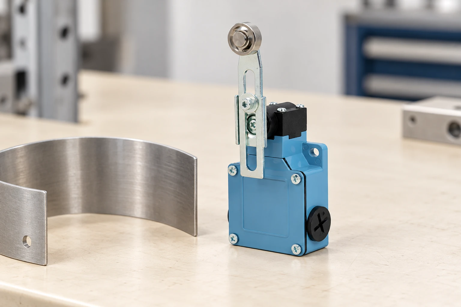
The LZ1 series limit switch provides a product reference for a roller-lever mechanism and an enclosed body. Its published enclosure information does not establish welding-spatter suitability, a cell-specific thermal limit or a safety function. Request evidence for the exact variant and proposed arrangement. If that evidence is unavailable, review another location or sensing strategy with the machine designer before approving an installation.
Examine the complete path from target to contact
A limit switch can look intact while deposits change the mechanical sequence. Material on the target can move the effective actuation point. Deposits near a roller can alter contact with the target. A restricted pivot or return path can prevent the mechanism from releasing as intended. These are assembly questions, so an inspection that checks only the enclosure surface is incomplete.
Start with the normal target approach, operating point, required movement and release position. Compare the actual arrangement with the approved drawing and switch instructions. Look for places where a deposit could reduce clearance, bridge a moving interface or redirect the target force. Preserve the intended approach to the actuator; do not move the switch until it merely produces a signal somewhere along the machine stroke.
The limit switch cam design guide explains approach, dwell and exit considerations. Use that background to define what must remain true after a protective change. A shield that avoids visible damage but interferes with the target path has not solved the problem. Record the necessary movement envelope so shield design and later maintenance can be assessed against the same reference.
Separate enclosure protection from hot-particle resistance
An enclosure ingress classification addresses specified ingress tests. It should not be expanded into a claim about hot metal adhesion, heat exposure, deposit removal or retained actuator performance. Likewise, a metal housing does not establish that every external part, cable, seal and marking can tolerate the local environment. Qualification must consider what is exposed and what failure would mean for the equipment.
Review the cable entry and nearby harness as carefully as the switch body. Hot particles may damage a cable or connector even where the main enclosure remains serviceable. The existing cable gland selection guide covers cable fit and entry questions. Add the welding-area exposure and protection requirements to that review; do not assume that an appropriate gland size proves thermal protection.
For the wider workplace context, NIOSH arc-welding electrical-safety guidance explains electrical hazards associated with welding work. It is authoritative background for planning work around welding operations. It does not prescribe a shield design for LZ1 switches or certify a proposed machine modification. The machine owner must determine applicable requirements and involve competent personnel in the design and validation.
Compare placement and shield options as an assembly
Relocation may reduce direct exposure, but it can change the target geometry, sensing point, cable routing and access for maintenance. A shield can reduce particle arrival while introducing a pocket where material accumulates. A replaceable sacrificial surface may simplify maintenance, provided its attachment and condition are controlled. Evaluate each option against the mechanical task and maintenance method, not only its appearance in a drawing.
Consider whether the proposed structure obstructs ventilation or traps heat near the component. Verify that it does not create an unintended contact point with the target, actuator or cable. Include the space required for fasteners, tool access and removal. A shield should not require workers to reach into an unsafe position merely to see whether the switch can still move.
Avoid assigning a generic sheet thickness, clearance or material to every installation. Those choices depend on the process, exposure, machine geometry and applicable requirements. Use engineering analysis and representative evaluation to establish the design. When comparing quotations, ask suppliers to identify their assumptions and evidence rather than accepting an unexplained description such as welding-proof cover.
Use a focused design-review checklist
| Review item | Evidence to collect | Acceptance question |
|---|---|---|
| Particle arrival | Actual process and deposit observations | Does the layout reduce exposure at vulnerable interfaces? |
| Moving mechanism | Target envelope and roller-return checks | Is operation and release preserved? |
| Protective structure | Released drawing and representative evaluation | Does the shield avoid interference and trapped deposits? |
| Cable and entry | Exact routing, materials and local protection | Is the full exposed path addressed? |
| Maintenance | Authorized access and removal procedure | Can deterioration be detected and handled safely? |
This checklist identifies the evidence to collect. It does not replace a machine risk assessment or a validated maintenance procedure. Give each requirement an owner and reference it to the released drawing or report. An unresolved row should remain visible during procurement so cost or lead-time decisions do not silently remove an essential protection feature.
Verify actuation after protective changes
Establish an isolated baseline for the installed mechanism before modifying its protection. Record the switch identity, mounting, actuator orientation, target path and observed contact sequence. After the authorized change, verify that the same functional requirements are met through the intended operating range. Include release behavior, because a switch that operates correctly once can still fail to return when an obstruction develops.
The mounting position and repeatability guide provides background for identifying position-related errors. For the welding application, use the actual mechanical setup and appropriate measurement method. A test with the target removed can help isolate a mechanism problem, but it cannot validate the final target-to-switch relationship. Keep each observation tied to the configuration actually tested.
Where the signal contributes to a protective function, changes require the appropriate machine-safety review. A general-purpose switch, a successful continuity check and an added shield do not together establish a safety-rated function. The responsible designer must evaluate the complete architecture and stopping behavior. Do not bypass a protective device to make a modified arrangement appear functional during production.
Define inspection and removal methods before deposits build up
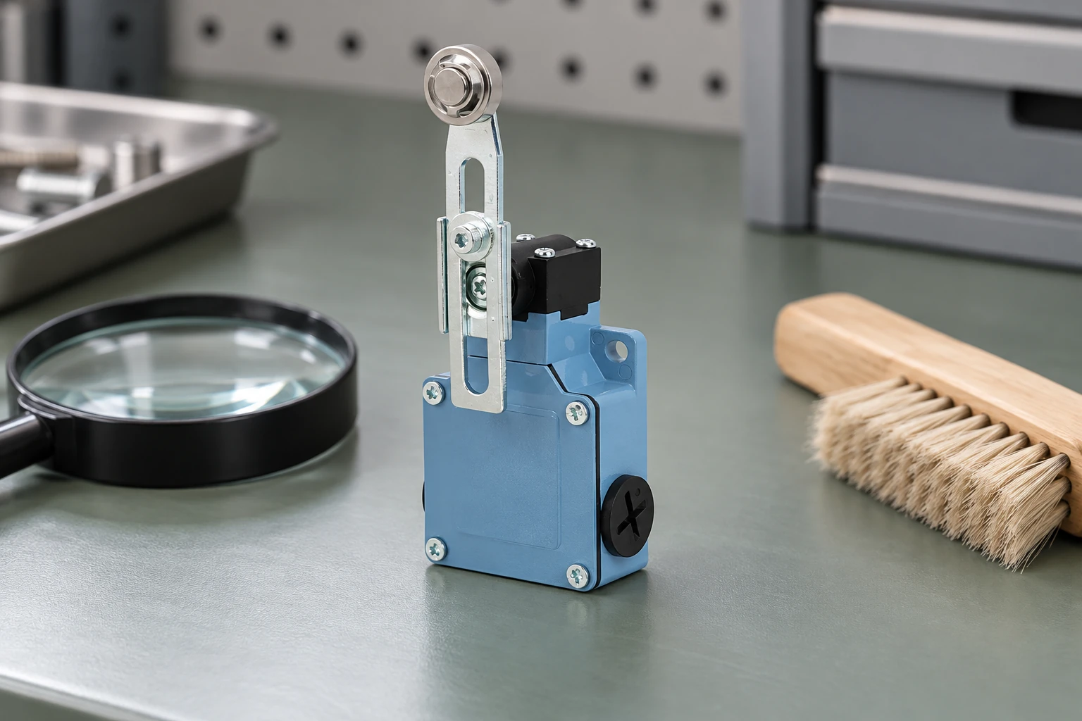
An inspection plan should state what can be observed safely, what requires isolation and which findings stop further use pending assessment. Relevant findings may include deposits near moving interfaces, damaged cables, changed target surfaces, loose protection parts and altered operating or release behavior. Set the inspection frequency from the actual exposure and operating experience; this guide does not assign an unsupported universal interval.
Cleaning is also a controlled task. Scraping or grinding deposits from a switch can damage the actuator, enclosure, seals or marking, and can move debris into sensitive areas. Do not apply an anti-spatter chemical to the assembly without compatibility evidence and an approved process. A chemical intended for a workpiece or welding nozzle is not automatically suitable for electrical controls, cable jackets or switch mechanisms.
OSHA’s hazardous-energy control requirements provide the relevant U.S. framework for covered servicing activities. The equipment-specific procedure must identify and control applicable energy sources. A stopped automatic cycle or a disabled input is not a substitute for the required isolation process. Maintenance personnel should follow the authorized procedure before reaching the switch or removing protection components.
Learn the process without transferring unsupported claims
The following NPTEL educational lecture introduces welding processes and their physical background. It can help purchasing and maintenance teams understand why process identification matters when discussing local exposure. It is not a switch qualification test, a shield-design specification or evidence of suitability for any Lemaele product. Use the lecture alongside the machine-specific process information and approved engineering records.
NPTEL-NOC IITM: #1 Introduction to Welding Processes

Watch #1 Introduction to Welding Processes.
Make replacement and procurement requirements explicit
When replacing a damaged switch, preserve the approved part identity, contact function, actuator arrangement and mounting relationship. Investigate why exposure reached the component before treating a fresh replacement as a permanent solution. Compare deposits, cable condition and operating-point observations with earlier inspection records. Repeated damage at the same location indicates that the protective arrangement or maintenance strategy needs review.
An RFQ should include the exact switch drawing, process description, exposure boundary, shield responsibility, cable protection and acceptance checks. Ask which documentation covers the delivered configuration and which claims remain unverified. Keep the agreed limits in the production record so a later supplier substitution does not remove a feature that the machine depends on.
Release the arrangement only when the mechanical task, environmental assumptions, inspection access and change responsibilities are understood. The useful outcome is a maintainable installation with supported boundaries. A generic claim of spatter resistance without an identified configuration leaves the most important questions unanswered: where particles can collect, whether the mechanism can return, and how the equipment owner will detect deterioration.
For the wider component selection review, use the industrial limit switch selection checklist. Add the application-specific evidence above to the normal mechanical and electrical requirements.
Frequently asked questions
Does IP66 prove resistance to welding spatter?
No. Specified ingress tests do not establish molten-particle resistance, thermal durability, deposit-removal compatibility or retained actuator motion.
Can anti-spatter spray be applied to any limit switch?
No. The exact assembly needs chemical-compatibility evidence and an approved process. A workpiece or nozzle product is not automatically suitable for electrical controls.
What is the universal safe distance from welding?
No universal distance is assigned. Process, particle paths, reflections, machine motion and local temperatures require application-specific evaluation.
Does an added shield make LZ1 a safety-rated welding-cell switch?
No. Shielding does not establish a safety function, a welding approval or suitability of the complete control architecture.