
Push button cap molding flash inspection should distinguish excess material from an ordinary parting witness, then evaluate the affected edge against the approved appearance and functional requirements. A visible line is not automatically a reject, and a neat photograph cannot prove that the cap moves freely in its installed arrangement. Identify the ordered button, record the location and extent of the suspected flash, and obtain a supplier disposition before trimming it. This guide gives buyers a practical way to collect edge photographs, compare retained samples and ask the right questions without guessing the cap resin, mold construction or allowable flash dimensions.
Identify the cap and the inspection question
Start with the ordered button variant, cap color, illumination option and drawing revision. Give each inspected sample a unique identity. The edge being assessed may belong to the cap, its surrounding collar or another molded part, and those locations have different functions. Label the feature on an overview photograph before requesting a close examination so the supplier can recognize the exact surface.
The Lemaele PBS series push button is the product reference for this guide. The family includes different colors and options, so the photograph of one assembly is not a universal appearance master. The public product reference does not identify a cap resin grade, molding process setting or flash tolerance. Ask the supplier for the applicable controlled requirement rather than importing a generic limit from an unrelated molded component.
Separate a witness line from excess material
A parting witness can show where tooling surfaces meet, while flash involves material extending beyond the intended molded shape. Do not classify a feature solely from a shadow in one image. Change the lighting and viewing direction, keep the sample orientation recorded, and compare the questioned location with the approved geometry or retained appearance sample. Where identification remains uncertain, ask the supplier to mark the feature.
The NPTEL lesson on injection molding lists flash among common molding defects. This is manufacturing background, not evidence that a particular PBS sample is defective. It does not establish how the sample was molded or authorize a buyer to change the process. The inspection decision should still rest on the ordered component and its agreed requirements.
| Evidence item | What to verify | Decision supported |
|---|---|---|
| Feature identity | Marked overview and supplier confirmation | Distinguish witness from excess material |
| Operator-contact edge | Location, appearance and qualified review | Address handling concerns |
| Moving clearance | Approved assembly and controlled observation | Assess possible interference |
| Dimensional condition | Defined characteristic and suitable report | Compare with the agreed requirement |
| Shipment scope | Samples examined, affected quantity and lot | Obtain a bounded disposition |
Map the edge according to its function
Separate operator-contact edges, moving clearances, visible cosmetic surfaces and seating or retention interfaces. An excess feature in a moving clearance deserves a different review from a permitted witness on a hidden surface. Record the affected zone and the concern it creates: interference, loose material, uncomfortable contact, appearance variation or an unresolved dimensional question. Do not treat every zone with a single unexplained visual rule.
The table below is a proposed purchasing checklist, not a PBS acceptance specification. It describes the evidence to collect before a responsible reviewer decides. Any numerical limit must come from an approved drawing, appearance standard or agreed inspection instruction. If no such requirement exists, establish it with the supplier and equipment designer before turning a subjective observation into a lot rejection.
Photograph the condition reproducibly
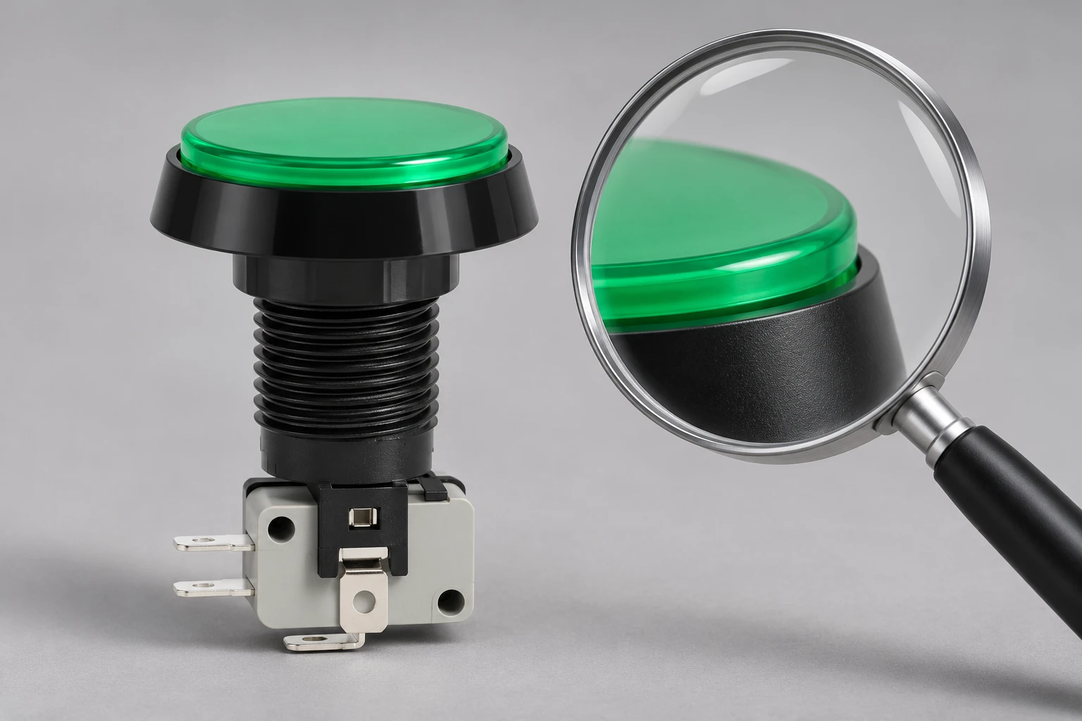
Take a full assembly overview and closer views that retain enough surrounding detail to locate the edge. Use stable lighting and focus; capture the same location from another direction if glare hides its contour. Keep original image files with the sample record. A magnified image is useful for finding and discussing a condition, but it can exaggerate appearance compared with the agreed normal viewing distance.
If a scale is needed, arrange it in a way appropriate to the measurement and avoid claiming a dimension from a perspective photograph. Record the actual instrument result separately when a dimension is required. Do not digitally remove the questioned feature or present a generated illustration as a production inspection photograph. The illustrations in this article explain the review context and are not evidence of a defect on supplied products.
Measure only a defined characteristic
Before measuring, state whether the requirement controls projection height, edge thickness, length along a boundary or another specific characteristic. Agree on the reference surface and direction. Without that definition, two inspectors may produce different numbers from the same sample while both believe they checked flash. Select an instrument that can access the feature without bending the cap or flattening the excess material.
Where the result is used for acceptance, document the instrument, method and relevant uncertainty. The NIST discussion of dimensional accuracy and traceability provides background on the distinction between measurement error and uncertainty. Its research context is not a button-cap tolerance. Ask the quality team to establish a suitable method and decision rule for the actual molded feature.
Investigate fit separately from appearance
A cosmetic review cannot establish whether the complete button operates as intended. If interference is suspected, assess the approved assembly under a controlled procedure with equipment safely isolated as required by the responsible team. Identify the panel, mounting arrangement and sample used. Observe the relevant movement and clearance without assuming that a visible edge feature is the only possible cause of a sticking complaint.
Keep that functional record separate from the appearance photographs. Panel coating, mounting conditions and component configuration can affect the investigation, so describe them rather than blaming molding from the first image. The guide to sticking after panel recoating addresses a different trigger. Comparing these records can prevent a panel-related problem from being mislabeled as a cap defect.

Preserve samples before requesting a disposition
Retain questioned samples in their observed condition, with packaging and shipment information where useful. Label any sample that has already been operated, disassembled or modified. Keep loose particles with a clear account of where they were found rather than assuming their origin. If a sharp edge or possible interference creates a concern, hold the affected sample for qualified review instead of continuing an improvised test.
Do not scrape, sand, heat or cut the cap as an informal receiving repair. A modification can change its appearance, leave debris or conceal the evidence needed for the supplier’s investigation. Any rework should have a written authorization that identifies the method, scope and required reinspection. Ask whether replacement is the appropriate disposition when a controlled repair cannot be justified.
Send a complete supplier evidence package
Provide the order code, drawing revision, lot or shipment identity, sample quantity examined and quantity showing the condition. Add the location map, original photographs and any defined measurements or functional observations. Separate observation from interpretation: “raised material along this edge” communicates more reliably than “bad molding” when the production cause has not been established.
Ask whether the feature is intended, whether it meets the applicable requirement, and what disposition covers the shipment. Request a response that names the samples reviewed. The custom push button RFQ checklist helps organize future purchase requirements, while the cap sink mark inspection guide covers depressions rather than excess edge material. Keep those different conditions identifiable in the quality record.
Carry the accepted requirement into repeat orders
When the issue is resolved, retain the approved appearance reference, inspection method and supplier response together. Record whether acceptance is limited to a particular shipment or establishes a future requirement. If a cap, tool or configuration changes, ask whether the earlier reference still applies. A family name and a color description alone may not identify the exact version evaluated.
Decide how incoming samples will be compared and who reviews borderline conditions. The goal is not to magnify every molding witness until it looks unacceptable; it is to establish a repeatable relationship between actual geometry, intended function and agreed appearance. A clear location-based rule reduces disputes, protects the equipment’s operation and makes future button purchases easier to verify without introducing unsupported material or process claims.
Example: an edge looks different under magnification
Suppose a receiving inspector finds a narrow raised-looking line around one cap in a magnified photograph. First identify the sample and location, then repeat the observation under the agreed appearance conditions. Compare it with the approved reference and obtain the supplier’s feature identification. If the concern is clearance, request the separate controlled functional assessment rather than assuming that a larger photograph demonstrates interference. Record both observations even if the visible line proves acceptable. This preserves useful evidence without treating magnification itself as a rejection criterion or making an unsupported judgment about the production mold.
Further learning
This NPTEL-NOC IITM lecture introduces injection moulding as background for understanding molded features. It does not demonstrate a PBS inspection or authorize changes to a supplier’s molding process.
Frequently asked questions
Is every visible cap seam flash?
No. A witness line and material extending beyond the intended geometry are different conditions. Confirm the feature against approved requirements.
Can a buyer trim the edge before inspection?
Preserve the original condition for review. Rework needs an approved method and defined reinspection, not an informal receiving repair.
What flash height is acceptable on PBS caps?
No universal limit is established here. Obtain the location-specific requirement for the ordered configuration from the approved drawing or agreed inspection instruction.
Does an acceptable appearance prove free movement?
No. Appearance and operation are separate checks. Evaluate suspected interference using the approved complete assembly and a controlled procedure.