
Preserve the original switching function
A toggle switch replacement needs to match poles, throws, maintained or momentary action, contact ratings, panel mounting and terminal arrangement. The same number of pins or a similar metal lever does not establish interchangeability. Begin with the equipment circuit and original order code, build a contact-state table, and compare the candidate’s current specification. For OEM equipment, a different part is a controlled substitution that requires functional validation. This guide focuses on panel-mounted equipment controls, including the Bereich der LEMA-Schaltflächen, rather than household wall-switch wiring, musical-instrument modifications or vehicle-specific repairs.
If the equipment manufacturer specifies an approved service part, use that instruction as the starting point. A generic selection checklist cannot override approval requirements or establish that an unlisted component is suitable. Preserve the original machine function and investigate why the old part failed before installing another switch.
For the wider operating principle and selection context, see the toggle switch mechanism guide. For a termination comparison, use the solder, screw and quick-connect terminal guide. These references support the replacement comparison; the exact part drawing still controls acceptance.
Document the old switch and its circuit
Collect the complete switch markings, part number and any suffix. Photograph the actuator, panel mounting and terminal side after following the equipment isolation procedure. Note the orientation of the lever and any locating tab, keyed washer or anti-rotation feature. Record which position corresponds to the displayed equipment command and which circuits are connected in that position.
Identify the connected load from the diagram. A toggle can carry load current directly, operate a relay coil or provide a controller input. Those roles impose different requirements. Document voltage, AC or DC, steady current and relevant starting or switching conditions. If the equipment drawing is unavailable, do not use terminal count as a substitute for understanding the circuit.
Label wires by their circuit and terminal designations before disconnecting them. Do not rely on wire color or a remembered pin arrangement. Record mating connector dimensions and the conductor termination method. Keep the original part as evidence, especially if damage makes the ratings hard to read. A purchasing description such as “three-pin on/off switch” omits too much information for a reliable substitution.
Compare poles and throws with a state table
A pole is an electrically independent switched circuit. A throw is a selectable contact path for a pole. These descriptions help identify the contact arrangement, but they do not tell you the complete behavior at every lever position. Refer to the exact contact diagram for the original and replacement, especially for multi-pole or center-position models.
Build a table listing every lever position and the terminal pairs expected to be connected. Include the center position when present. Compare the released position separately for spring-return devices. Two switches described as three-position can have different maintained and momentary combinations, and a center position is not always electrically off.
For a broader explanation, use the SPDT toggle switch wiring guide. The replacement decision is more specific: it must preserve the original circuit state in every intended position. Do not bridge terminals or add a jumper to compensate for a different contact diagram without an approved circuit redesign.
| Requirement | Comparison method | Substitution concern |
|---|---|---|
| Poles and throws | Compare the exact contact diagrams | A circuit is missing, joined or routed differently |
| Aktion | Record maintained and spring-return positions | A temporary command becomes a maintained command |
| Lever position | Compare mechanical position with the equipment label | Displayed direction disagrees with the electrical state |
| Load rating | Match voltage, AC/DC and connected load duty | Only the largest current marking matches |
| Schalttafeleinbau | Compare cutout, thickness, bushing and clearance | Mounting requires forcing or leaves insufficient thread |
| Terminals | Confirm geometry and approved connection method | Mating connector is loose or wiring is strained |
This is a qualitative comparison matrix. Exact dimensions, ratings and tolerances must come from the component drawings and equipment documentation; the table supplies no universal acceptance limits.
Keep momentary and maintained actions distinct
A maintained lever remains in its selected position after the operator releases it. A momentary position returns under spring action. Changing between them can alter how long a command stays active. This matters when the switch controls movement, pump operation or a machine mode. A replacement that looks correct may change the process behavior if its return action differs.
Write down action separately for each side of the center position. Do not assume both directions return simply because one does. Confirm the supplier’s action notation rather than interpreting punctuation from a marketplace title. The momentary toggle switch guide provides complementary background on spring-return operation.
Consider power restoration and controller logic as part of functional validation. A maintained switch can retain a command while power is absent, but actual restart behavior belongs to the complete machine control design. A spring-return switch also does not by itself guarantee a safe response. Preserve the equipment’s required restart and fault behavior rather than making an assumption based on the lever mechanism.
Match electrical duty without extrapolating ratings
Check the rated voltage and whether each rating applies to AC or DC. Do not transfer an AC current marking to a DC circuit. Identify whether the connected load is resistive, inductive or another specified duty. Relay coils and motors may impose different switching requirements from a resistive load, even where the measured steady current seems modest.
For controller inputs, confirm the permitted signal voltage, current and contact material. A high-current switch is not automatically suitable for a very low-current input. Also preserve any specified insulation or separation requirements. These are component selection questions for the exact order code; a photograph cannot answer them.
If the original contacts welded or the body overheated, review the circuit and connection condition. Inrush, an inappropriate load rating, a loose terminal or an inadequate termination may be involved. Do not fit another visually identical switch and declare the cause corrected. Where the design uses a relay interface, retain that function. The RealPars video later in this article explains the separation between a command contact and a relay-controlled circuit.
Check the panel cutout, bushing and clearances
Compare the threaded bushing diameter, locating features, allowable panel thickness and available thread engagement. Use the specified mounting nut, washer arrangement and assembly torque. A nut that can be tightened does not prove that the switch is correctly retained or sealed. Excessive force can damage threads, deform a panel or stress the housing.
Check the space behind the panel for the terminal assembly and connected conductors. Allow for the specified connector insertion and cable routing without pressing conductors against adjacent parts. Confirm lever clearance across every position, including any boot or guard. Panel labels must remain readable and must match the installed orientation.
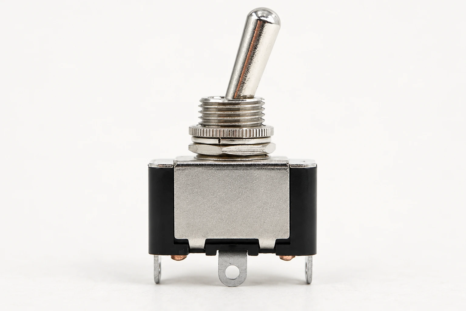
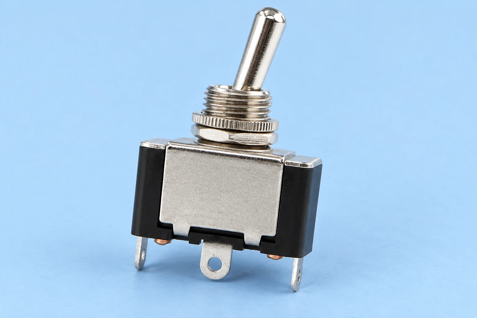
The images here are illustrations based on the real LEMA LT2120A reference, showing a metal lever, threaded bushing and body features. They do not establish a particular terminal circuit, environmental rating or compatibility with another manufacturer’s switch. Request the selected model’s current drawing before accepting it as a replacement.
Inspect environmental and connection requirements
Check local temperature, dust, moisture, cleaning chemicals and vibration. Confirm what part of the installation any protection rating covers. An actuator boot may protect one boundary while the rear terminals remain exposed. Retain the original sealing method or use a documented replacement arrangement; do not assume that a rubber cover makes an assembly waterproof.
Match solder lugs, blade terminals or screw terminals to the intended connection method. Inspect the mating connector and strain relief, and replace damaged connection parts under the equipment instructions. Do not bend blades to accommodate an incorrect connector spacing. The assembly must support conductors so routine vibration or operator use does not load the terminals.
For a production substitution, compare approved assembly processes as well as the purchased part. A different terminal style may require revised tooling, inspection criteria and work instructions. That is a process change, even if the electrical diagram remains the same.
Validate the installed function under controlled conditions
Maintenance requires the equipment’s authorized isolation and test procedure. The OSHA hazardous energy guidance addresses unexpected energization and stored energy during service. A toggle’s off position is a control state and must not be assumed to provide the isolation required for maintenance.
On an isolated contact circuit, check the documented terminal connections in each lever position and confirm the return action. This establishes contact behavior at the test conditions, not load endurance or insulation performance. Then follow the equipment commissioning procedure to verify the actual controller signal, equipment response and restart behavior. Do not bypass protective functions to simplify this test.
Das HSE machinery maintenance guidance supports planned work by competent people with suitable instructions. If a substitution affects a protective function, hold the change until the required engineering assessment and verification are complete.
RealPars explains how a relay system separates command contacts from the switched circuit in the educational video below. It helps identify what role the toggle plays, but does not prescribe a replacement or authorize a circuit modification.
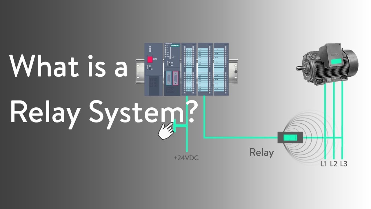
Watch the RealPars relay explanation on YouTube.
Prepare a replacement inquiry and retain the record
Send the original order code, circuit-state table, panel drawing, terminal photographs, connected load and environmental conditions through LEMA’s contact page. Specify annual quantity and any approval or traceability requirements. Ask for confirmation of each requirement rather than a broad claim that a part is “equivalent.”
Retain the accepted comparison, drawing revisions, test results and installed part number. For repeat production, update the bill of materials, assembly instructions and inspection record. If a critical characteristic cannot be confirmed, keep the original approved specification and hold the substitution.
Häufig gestellte Fragen
Can a three-pin toggle replace any other three-pin toggle?
No. Terminal count does not establish contact arrangement, action, physical terminal positions, ratings or panel fit. Compare the exact contact diagrams and installation drawings.
Can I use an AC-rated toggle in a DC circuit?
Only when the exact component has a suitable DC rating for the actual load. Do not infer DC capability from an AC voltage and current marking.
Is a center-position toggle always off in the middle?
No. The center electrical state depends on the particular contact arrangement. Confirm the manufacturer’s diagram and the required equipment state.
Does matching the panel hole prove compatibility?
No. Also check panel thickness, bushing engagement, locating features, rear clearance, terminals, circuit function, action and environmental requirements.