
Micro switch lever length should be chosen from the mechanism’s motion, contact point, required operating force and permitted travel. A longer lever can change mechanical advantage, but it also changes displacement and the moving envelope. Measure from the relevant pivot or reference defined in the switch drawing, not merely the exposed metal strip. Select a complete actuator variant and verify operation and release in the real mechanism rather than bending a stock lever until it seems to work.
This guide focuses on choosing lever geometry for repeatable OEM position detection. It complements the broader actuator-types and force-selection guides. LEMA KW7 roller-lever micro switches are the product reference; the illustrations are not dimensioned drawings or permission to modify the actuator.
Define what the mechanism needs to detect
Start with the target event: a part reaches a position, a cam rotates through a point, a door closes or an item passes a sensing station. Record both the required operating state and the release state. Decide whether the controller needs a held condition, a pulse or a change of state. Lever selection must support that function across the expected movement.
Identify the available motion at the intended switch location. Include approach direction, displacement, speed and how accurately the target is guided. A lever that reaches a distant target may solve packaging but introduce sensitivity to lateral motion. Where the target location is uncertain, compare a different mounting position before assuming that a longer lever is the best correction.
Read the actuator-specific drawing
Obtain the full switch order code and drawing for the actual lever or roller option. Identify the pivot, permitted contact region, operating position, release behavior and maximum allowed travel. A body-family drawing without actuator details may be insufficient. Ask the supplier which force and travel measurements apply to the selected lever.
Do not interchange bare plunger data and lever-contact data without understanding how they are defined. The operating force at the end of a lever can differ from the force at the internal mechanism. Likewise, travel at a remote contact point can be different from plunger travel. Record the measurement point and direction next to every force or displacement value in the design file.
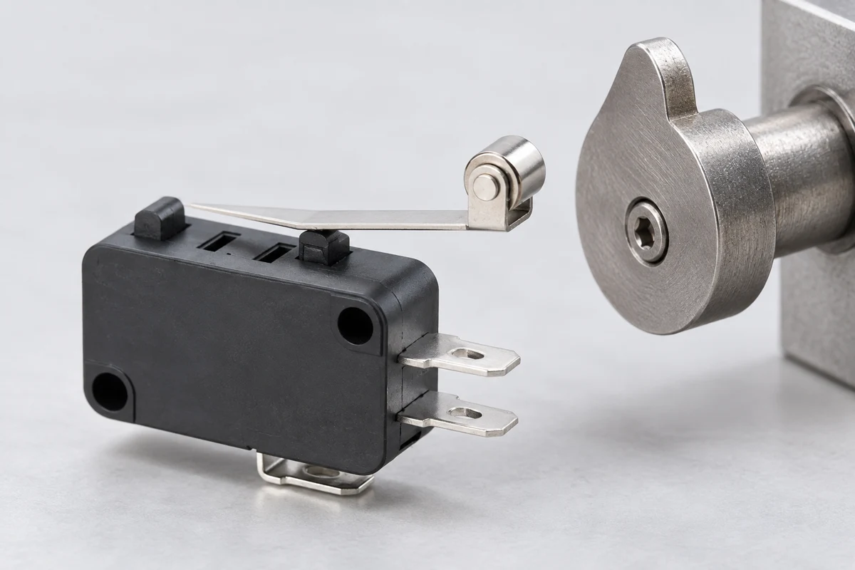
Use lever-arm reasoning with clear limits
For an ideal rigid lever under quasi-static perpendicular loading, torque equals force multiplied by the perpendicular lever arm. The OpenStax torque reference explains this relationship. If the required torque were unchanged, increasing the effective lever arm would reduce the required force. That is an explanatory model, not a switch rating or a prediction that ignores its spring and contact geometry.
An illustrative calculation is a torque of 0.006 newton metres applied at a perpendicular arm of 0.012 metres, giving 0.5 newtons. At 0.024 metres the same ideal torque corresponds to 0.25 newtons. These are hypothetical values for units and interpretation, not LEMA specifications. Real levers can flex and the angle changes during motion; obtain the actual operating data and validate the mechanism.
Balance reduced force against added displacement
A longer contact radius moves through a larger arc for the same rotation angle. In the ideal small-angle relation, displacement is approximately radius multiplied by angle in radians. For a hypothetical angle of 0.02 radians, a 0.012-metre radius gives about 0.24 millimetres, while 0.024 metres gives about 0.48 millimetres. The approximation is only for small rotations and is not the switch’s operating-travel specification.
This explains why lowering target force may demand additional target movement. Check whether the mechanism has that movement available before reaching its stop. Compare the actual supplier operating and release positions with the tolerance range of the target. Do not choose leverage using force alone and then discover that the machine cannot move far enough to operate reliably.
| Mechanism question | Lever-selection implication | Verifizierung |
|---|---|---|
| Limited available force | Compare actual contact-point force | Model data and assembled measurement |
| Limited available movement | Longer radius can require more travel | Operating and release positions |
| Changing approach direction | Effective lever arm can vary | Target profile and permitted contact region |
| Tight neighboring clearance | Include full lever motion | Released and operated envelope |
| Uncertain repeatability | Check mount and target before resizing | Position and release review |
Place the contact point where the drawing permits
Record where the target touches the lever and whether that point can shift during operation. A broad or poorly guided cam can change the effective lever arm and contact direction. A target that slides toward the pivot can increase the force required or alter the switching position. Use geometry that controls the intended contact region.
For a roller option, verify the permitted direction of rolling contact and the approach profile. The roller is not permission to apply arbitrary side loads. Check that the target does not catch the edge, strike the housing or trap the lever after operation. If the permitted approach is unclear, ask for a model-specific installation diagram rather than relying on a generic micro switch image.
Treat the lever as a moving envelope
Include the lever or roller at released, operated and maximum permitted positions in the layout. A lever can clear neighboring parts while released yet contact a guard or harness during operation. Add the relevant tolerance and adjustment range. Check the full mechanism, including covers that are fitted late in assembly.
Do not use the switch as an uncontrolled mechanical stop. Provide the intended stop or travel limitation in the mechanism design. Verify that the target can leave the lever and that the actuator returns freely. A longer lever may also be easier to snag during assembly or service, so include handling and access in the packaging decision.
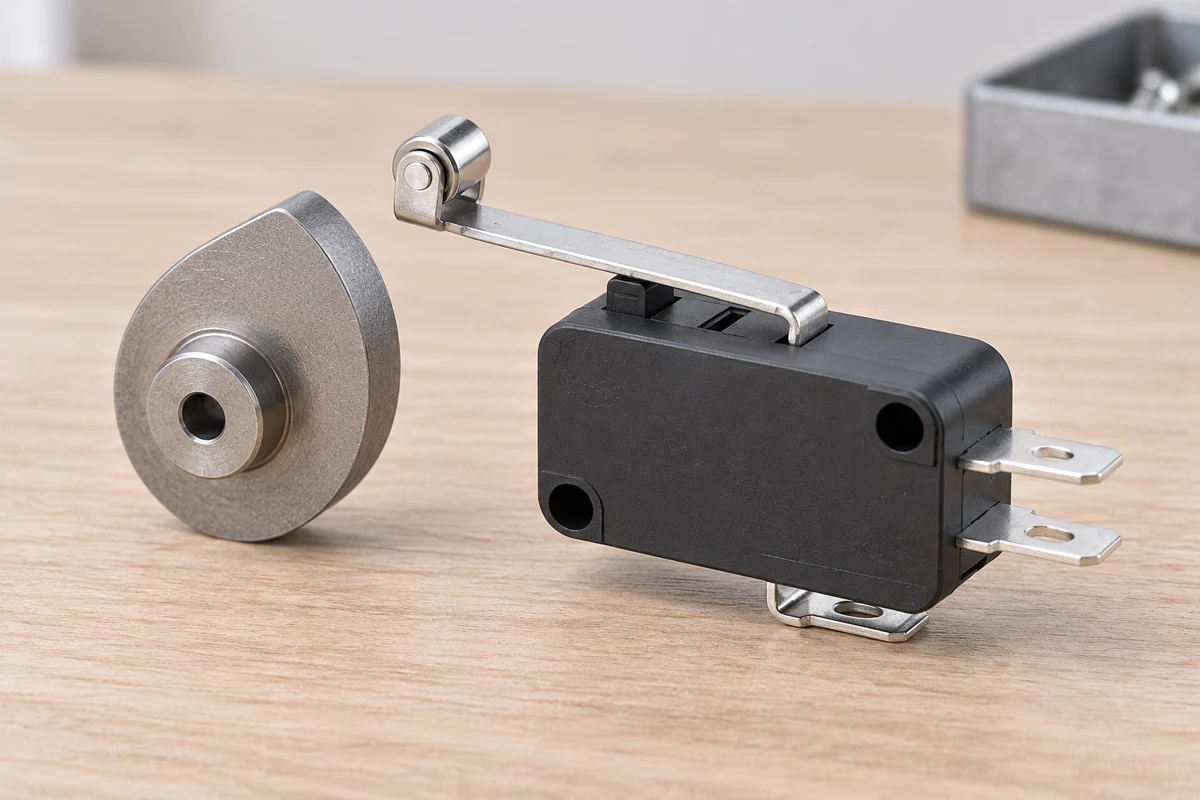
Check bracket stiffness and alignment
A lever cannot compensate for a mounting bracket that moves unpredictably. Observe the switch body and bracket while the target approaches. Flexing support can shift the operating point even if the lever motion appears smooth. Compare mounting-hole position, fastener arrangement and local stiffness with the intended repeatability requirement.
Define how adjustments are made and locked. Avoid undocumented lever bending as a production setting method. If the supplier supports a particular adjustment, record its limits and procedure. Otherwise, select the correct actuator variant or revise the mount. Preserve an approved assembly sample that shows the intended contact location and released clearance so operators do not reproduce a visually plausible but different arrangement.
Consider speed, impact and repeated crossing
A static force calculation does not describe a target striking the lever at speed. Approach profile, acceleration, impact and mechanism vibration can affect actuation. Use an appropriate cam or contact surface to avoid abrupt collisions, and verify the switch maker’s applicable limits. Do not assume that a longer lever automatically absorbs an impact safely.
Check whether the mechanism crosses the operating and release boundary repeatedly near a dwell position. Multiple controller events can come from actual re-actuation rather than internal contact bounce. Observe the target motion alongside the electrical state. A debounce timer may hide the symptom while leaving unstable mechanical geometry unchanged. Refer to the separate contact-bounce guide when diagnosing signal behavior.
Run a repeatability and release review
Build the selected lever variant into a representative mechanism and record the target position at operation and release using a suitable method. Compare results with the equipment requirement, not a universal tolerance guessed for all switches. Include the relevant mounting, target and temperature conditions defined by the design authority.
Inspect the lever after the intended validation sequence for deformation or contact damage. Verify that wires and nearby parts do not restrict it. If the switch performs inconsistently, separate the effects of the target, bracket, lever geometry and internal switch before changing several items at once. Keep the rejected sample and observations so a later substitute does not repeat the same problem.
Give LEMA a mechanism-based lever inquiry
Send the target-motion sketch, approach direction, intended contact point, available space, force and travel constraints, circuit duty and environment. Identify the candidate switch family and request complete actuator-specific data. If your requirement uses a measurement at the roller center or lever tip, state that explicitly.
At sample approval, preserve the order code, actuator drawing, bracket drawing, assembly setting and acceptance results. Use those records when evaluating replacements. The objective is controlled switching and release over the specified mechanism range. Lever length is one design variable in that system, not an isolated purchasing number that guarantees sensitivity or service life.
Further learning
This lesson explains force and lever arms. The numerical example above is hypothetical; obtain the selected micro switch actuator data and verify the mechanism before design release.

Verwandte LEMA-Ressourcen
- How to Choose a Micro Switch Lever Length product reference
- Industrial micro switch selection
- Operating force at the actuator
- Pretravel, overtravel and differential travel
Technical references
- OpenStax torque and lever arms: Explains force and lever-arm relationships; switch operating force still comes from its model drawing.
- NASA wiring workmanship standard: A reference for controlled cable and harness workmanship; it does not certify the illustrated LEMA part.
Häufig gestellte Fragen
Does a longer lever always make a micro switch more sensitive?
No. It changes the force and displacement relationship, but real behavior depends on contact location, angle, lever stiffness and the switch mechanism. Compare actuator-specific data and validate the actual installation.
Can I calculate operating force from the body rating?
Not reliably without knowing how that rating is defined and the actuator geometry. Simple torque calculations explain trends but do not replace supplier force and travel data for the selected lever.
Can a lever be bent to match the target?
Only if the exact maker instructions permit a controlled modification. Otherwise bending changes geometry and behavior without a validated limit. Select an appropriate actuator option or revise the mounting arrangement.
How should lever length appear in an RFQ?
Specify the full actuator drawing, pivot or reference, contact point and required approach. Include target motion, operating force and travel constraints. A single overall length without those references is insufficient for a reliable comparison.