
Limit switch roller outside diameter measurement should identify the actual rolling surface, the axial measuring position and the approved dimensional requirement before a tool touches the part. A reading across the hub, a chamfer or an angled section is not automatically the roller diameter required by the drawing. This guide uses the real Lemaele LZ2108 roller switch as a purchasing reference and explains how to request reproducible dimensional evidence. It does not assign an unseen roller size, tolerance or material. Work on an isolated, stationary sample; dimensional inspection is separate from machine commissioning and safety-function validation.
Identify the roller configuration before measuring
Obtain the complete switch order code and actuator configuration. A family can include different heads, lever arrangements and target interfaces, so a dimension from a nearby model may not apply. Record whether the sample is new, previously installed or returned from service. A worn service specimen and an incoming production sample answer different questions.
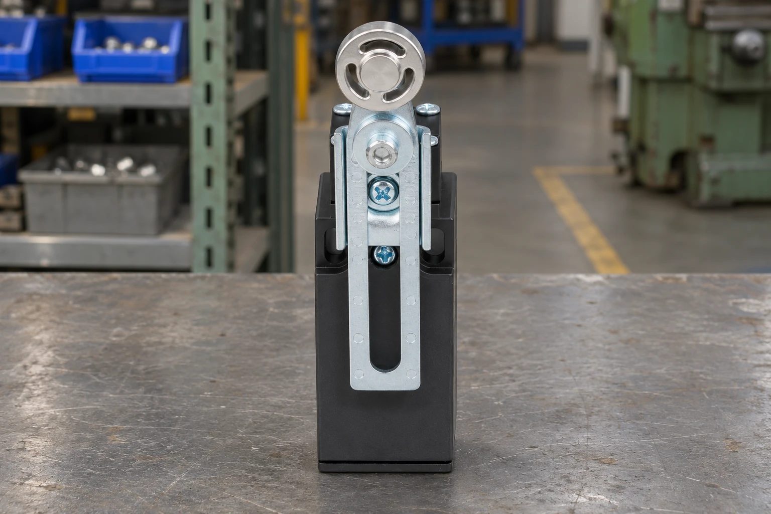
Das LZ2108 adjustable roller limit switch page provides the product reference for this discussion. Its photograph shows the roller arrangement, but a photograph does not establish a nominal diameter or a permissible deviation. Ask Lemaele for the controlled actuator drawing and dimensional requirement for the actual ordered version. Do not transfer a value from another limit-switch series.
Define the outside surface and the section
Identify the surface intended to contact the machine target. Keep that rolling surface separate from the center hub, retaining hardware, side faces and edge transitions. Specify the axial position or width region for the reading. If the roller is profiled rather than cylindrical, ask which section and definition the drawing requires instead of silently treating the entire width as one diameter.
Use an annotated photograph to show the section and a stable orientation reference. The measurement report should make it possible for another operator to return to that position. Note whether the instrument spans a chamfer, contacts an edge or reaches only part of the roller width. Those details can explain disagreement between two apparently precise readings.
| Evidence item | Was zu überprüfen ist | Decision supported |
|---|---|---|
| Konfiguration | Exact switch and actuator identity | Prevents borrowing a dimension from another head |
| Surface | Rolling band and axial section | Separates the outside surface from hub and edges |
| Zugang | Tool contacts and possible interference | Determines whether an assembled check is feasible |
| Methode | Alignment, support and force control | Improves reproducibility |
| Results | Positions, units and individual readings | Keeps variation visible |
| Disposition | Drawing limit, uncertainty and approval authority | Supports a controlled purchasing decision |
Prepare a stationary sample without altering the surface
Follow the equipment owner’s isolation and handling procedure before removing or inspecting an installed component. Do not measure a moving roller, work near an energized mechanism or use the switch as a fixture to restrain machine motion. For incoming inspection, a separate unpowered sample on a clean workbench usually makes the dimensional question easier to control.
Photograph the received condition before any permitted cleaning. Note visible particles, adherent material or a localized mark. Use only the supplier-approved handling and cleaning method; scraping the surface may remove evidence or change the feature. Refer a contaminated roller to the procedure described in roller debris and jamming inspection when contamination is the primary concern. Do not combine contamination removal with an undocumented dimensional rework.
Choose an instrument for the actual access
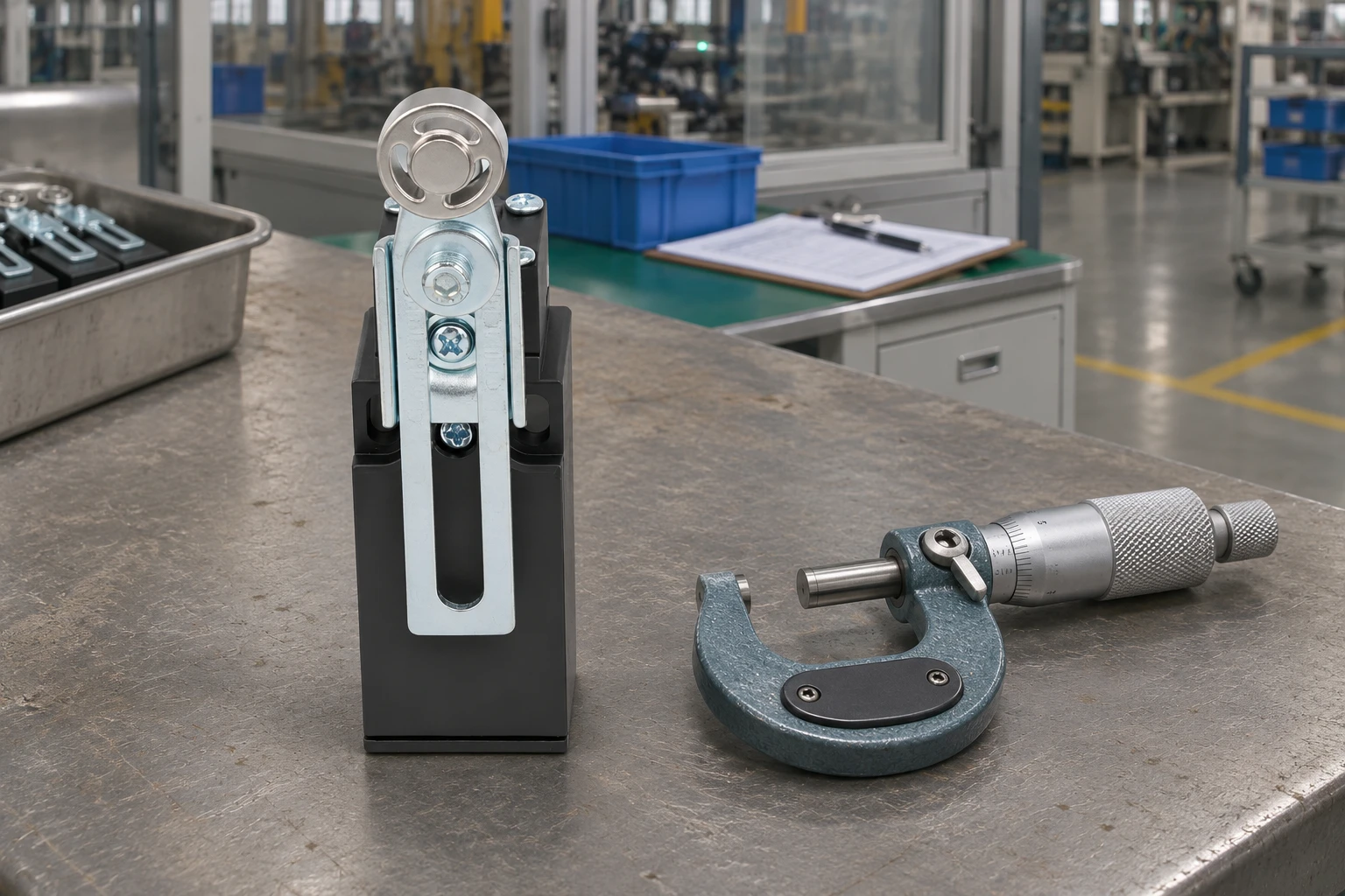
A caliper may reach an assembled roller where a conventional outside micrometer cannot. That does not make every caliper result adequate for every tolerance. Consider jaw contact, alignment, instrument condition, resolution and measurement uncertainty. If the lever or retaining hardware prevents correct positioning, stop and request a suitable fixture or method rather than taking an oblique reading.
The National Physical Laboratory Callipers and Micrometers guide discusses instrument selection, contact force, handling and uncertainty. These are relevant general measurement controls, not a roller-specific acceptance procedure. Ask the responsible metrologist to demonstrate how the chosen tool contacts the specified outside surface without touching the hub or side hardware. Avoid assuming that a smaller display increment guarantees a better result.
Control alignment and contact force
Keep the measuring direction aligned with the intended diameter section. A tool tilted across the width may contact different axial positions on opposite sides. A reading over an edge transition may represent a smaller section. Support the sample so the operator does not need to pull against the lever or squeeze the assembly to keep it steady.
Use the instrument according to its approved operating method and avoid excessive contact force. Unknown surface material or local compliance is a reason to assess the method, not a reason to guess a safe force. Record unusual sensitivity to handling or positioning. Repeat placement according to the measurement plan, releasing and repositioning the tool where required, rather than merely rereading an unchanged display.
Separate diameter variation from runout and play
Diameter, roundness, runout and bearing play are related to different quantities. Opposed contact readings at several orientations can document size variation under a defined method; they do not automatically establish a full roundness profile. Runout requires a defined rotation reference and measurement arrangement. A loose assembly may complicate that reference without changing the roller’s actual outside size.
Das NIST Dimensional Metrology Group describes measurement work spanning dimensional characteristics and reference standards. It is background for selecting competent measurement support, not a claim that LZ2108 rollers have been evaluated by NIST. If the complaint is wobble, lateral movement or an inconsistent target contact, identify that question explicitly before ordering only a diameter check.
Record positions and individual readings
Create a measurement map naming axial position and angular orientation where these are part of the plan. Record the instrument identity, units, sample condition, operator, date and drawing revision. Keep each reading associated with its location. If a mark is used to identify orientation, place it only where the approved procedure allows and keep it away from the measured rolling surface. A photograph with a fixed external reference may be preferable when marking is not permitted. State how the sample was repositioned so the report does not imply that repeated readings came from an unchanged section when they did not. If the agreed procedure calls for multiple specimens, preserve the individual sample identities rather than presenting a single unidentified range.
Do not average away a result that may matter to a local minimum or maximum requirement. Equally, do not call an isolated reading a failed lot without the approved acceptance arrangement. The quality function should determine how the dimensional requirement, measurement uncertainty and sampling plan support a release decision. No universal sample count, roller tolerance or acceptance band is supplied here because those must come from the controlled purchase documents.
Connect the result to the mounting and target question
A verified roller diameter does not by itself establish switch operating position, repeatability or the safe travel available in the machine. Lever setting, housing location, target path and permitted overtravel remain separate application details. Use the roller limit-switch application guide to organize the broader application discussion after the dimensional requirement has been clarified.
For a suspected installation change, document the mounting reference as well. The mounting-datum measurement guide explains why comparable position measurements need a common reference. Avoid adjusting the lever merely to compensate for an unconfirmed roller discrepancy. Any authorized setup change should follow the machine and switch instructions and be recorded separately from the original dimensional observation.
Request an actionable supplier review
Send the order configuration, drawing requirement, sample identity, section map and individual readings. Include photographs showing the tool contact and any access limitation. Explain whether the objective is incoming conformity, investigation of wear or compatibility with an existing target. A request with those details is more useful than a close-up and a message that the roller looks too small.
If the supplier report and buyer result disagree, compare the measured sections, instrument contact and sample condition first. Agree a common method or independent laboratory review before changing the acceptance limit. Keep the original report, clarification and final disposition together. When no controlled dimension exists, resolve the design requirement before declaring conformity; a measurement can characterize an object without establishing whether it meets an unstated contractual limit.
Weiterbildung
This IIT KANPUR-NPTEL laboratory demonstration introduces dimensional instruments and handling concepts relevant to an outside-size check. It is not an LZ2108 inspection procedure or evidence that the pictured switch was measured.

Häufig gestellte Fragen
Can I measure the roller from a product photograph?
No. Perspective, image scaling and the absence of a verified reference prevent a reliable dimensional acceptance result. Use the controlled drawing and an appropriate measurement of the actual sample.
Does one outside-diameter reading prove roundness?
No. A single opposed-contact measurement describes one size under one setup. Roundness and runout require their own defined methods and reference arrangements.
Can a correct roller diameter prove correct switch operation?
No. Housing position, lever setting, target geometry and permitted travel also affect the application. Complete the separate installation and functional checks required by the equipment instructions.
What should I send when disputing a roller measurement?
Provide the exact configuration, drawing revision, sample condition, axial and angular measurement map, instrument details, individual results and photographs showing where the contacts were placed.