
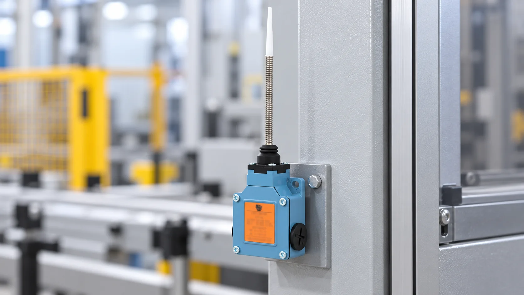
A heavy-duty limit switch should be selected by the loads and environment it must survive—not by the adjective on a catalog page. Start with the machine motion and the required switching point, then match an actuator, mounting position, enclosure protection, contact duty and service plan to that application. Ask for model-specific ratings and test evidence; “heavy duty” is not a universal certification or a substitute for an equipment risk assessment. LEMA’s LZ1 Series page, for example, lists an aluminum-alloy limit switch with an IP66 enclosure rating and separate AC-15 and DC-13 contact ratings. Those claims apply to the stated series information and must still be checked against the exact order code and machine design.
Define what “heavy duty” must withstand
Write down the stresses before comparing part numbers. A press, conveyor, hydraulic cylinder, outdoor mechanism and washdown machine can all be described as demanding, but they do not impose the same stresses. One may need a robust actuator and repeatable switching position; another may need a sealed enclosure, a corrosion-resistant mounting arrangement or a long cable-flex life. Treat each requirement separately instead of assuming that one rating covers every condition.
Build a short use profile: expected operating cycles, target approach speed, likely impact or side load, vibration, dust, liquid, cleaning chemistry, ambient temperature, cable movement and access for maintenance. Identify the consequence of a missed or false transition. If the switch is part of a safety-related control function, specify the required safety architecture and validated components separately; a general-purpose limit switch by itself does not establish a safety function.
Machine safeguarding is a system issue. OSHA describes guarding in terms of protecting operators from hazards such as points of operation, ingoing nip points and rotating parts, and calls for the safeguard to fit the hazard. Use the applicable machinery standard, risk assessment and control-system design for the equipment; do not treat a position switch as a stand-alone guard.
Match the actuator to the target motion
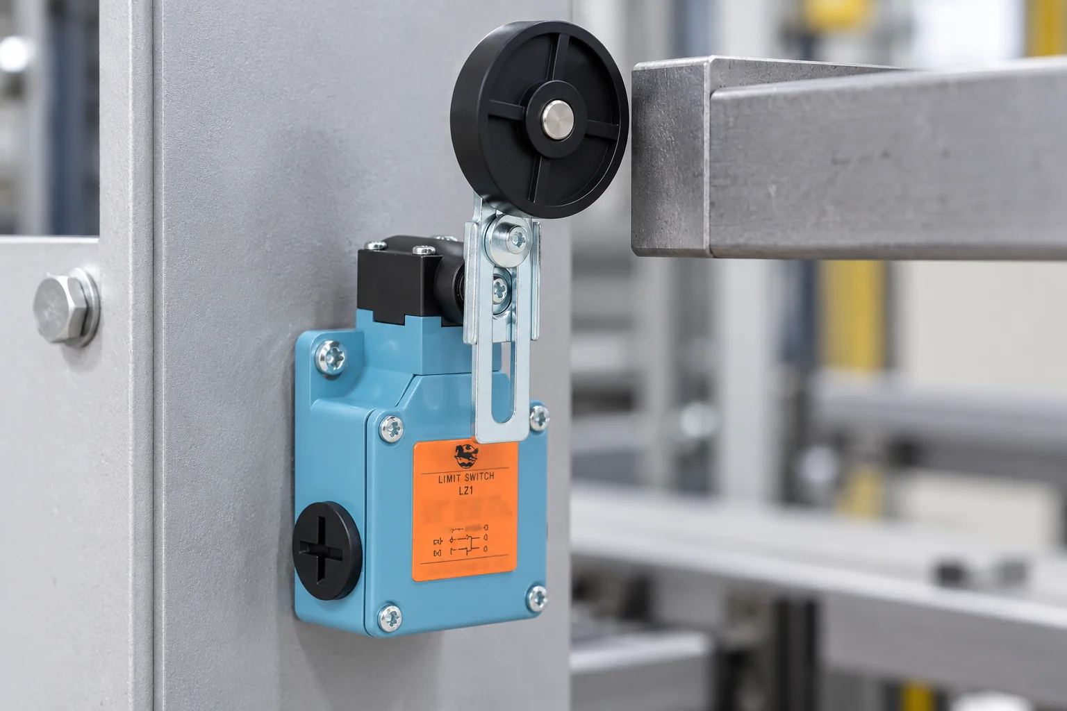
The actuator determines how the machine target reaches the switch. A plunger suits a direct, aligned press. A roller lever can accept a moving cam or passing surface, while a spring rod can respond to movement from more than one direction. These descriptions are starting points, not interchangeability rules: lever length, roller geometry, direction of approach, operating travel and permitted overtravel vary by model.
| Actuator style | Typical motion to evaluate | What to verify before release |
|---|---|---|
| Top plunger | Direct, approximately axial contact from a cam or stop | Alignment, force direction, operating travel, overtravel and hard-stop position |
| Rollenhebel | Cam or surface that moves across a roller | Approach direction, lever adjustment, roller path, side loading and clearance |
| Spring rod or whip | Target may contact from more than one direction | Deflection envelope, return path, snag risk and whether the machine can bend or fatigue the rod |
| Other lever or specialty head | Application-specific mechanical contact | Exact head variant, motion sequence, mounting orientation and manufacturer limits |
Do not set the operating point by forcing the actuator to the end of its travel. Establish a repeatable target position with a suitable margin, and ensure the machine stop—not the switch mechanism—takes any structural impact. For a practical mounting and repeatability workflow, see LEMA’s limit switch mounting position and repeatability guide.
Check the enclosure against the real environment
An IP code describes a defined degree of protection provided by an enclosure under the standard’s test framework. It does not automatically prove resistance to every oil, coolant, cleaning chemical, salt exposure, UV condition, temperature cycle or installation error. The IEC 60529 page identifies the IP Code as a classification of degrees of protection provided by enclosures. Use that code for what it states, then separately verify other environmental conditions and the completed installation.
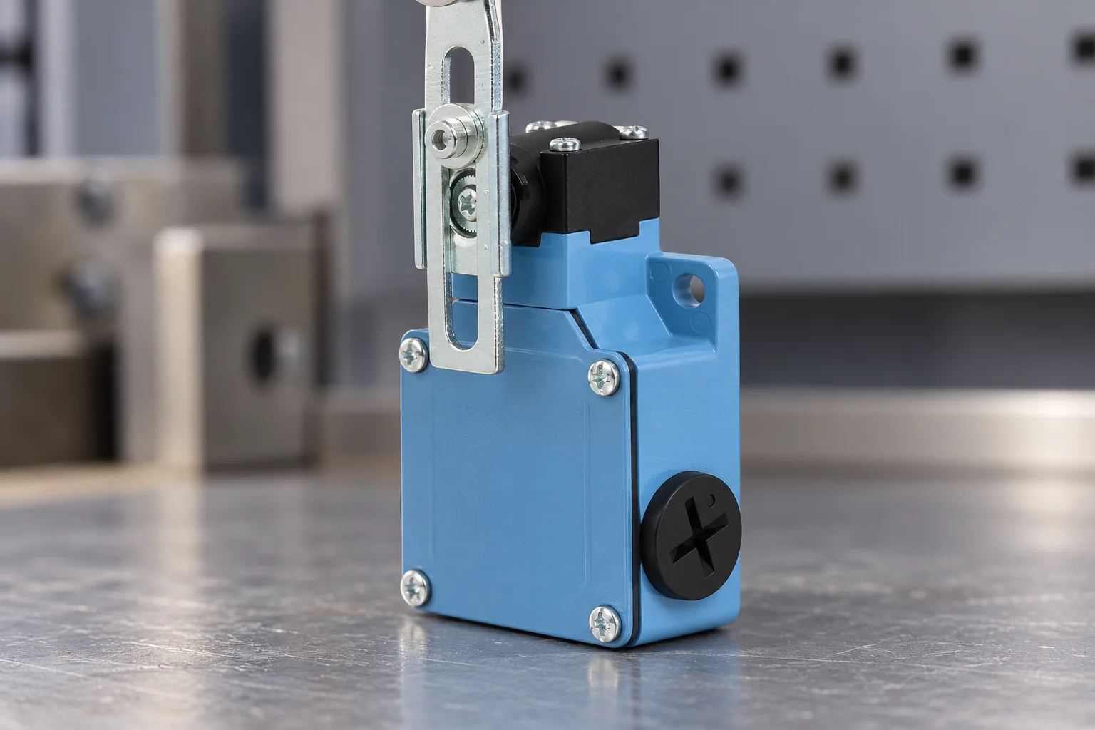
LEMA’s LZ1 page lists IP66 for the series information. That is useful when screening candidates, but it is not a blanket statement that every actuator arrangement, cable entry, connector, mounting orientation or system interface will retain the same protection after installation. Check the model drawing and sealing details, use the specified cable entry and gland, and avoid routing or clamping that pulls on the enclosure.
For vibration, shock and temperature, request the exact test conditions and the applicable model documentation. A general marketing phrase does not show the frequency range, displacement, mounting method, exposure time or acceptance criteria. When the machine runs near a limit, validate the installed assembly over the motion profile and environmental range that matter to the equipment.
Verify electrical duty, not just nominal current
Confirm what the contacts will switch. A PLC input, an interposing relay coil and a motor load create different electrical duties. AC and DC ratings are not interchangeable, and a resistive-load value does not automatically cover an inductive load. Document the control voltage, load category, steady and inrush current, switching frequency, expected electrical life and protective components with the equipment designer.
The LZ1 product page lists AC-15 at 250 V/6 A and DC-13 at 220 V/0.3 A, plus an initial contact-resistance value. Treat those as the page’s published LZ1-series data—not a universal rating for all limit switches. Confirm the exact model and current manufacturer datasheet before design approval. If a contact drives a coil or other inductive load, confirm whether suppression is required and how it affects release time and the control behavior.
When a limit switch reports a machine position to a PLC, verify the expected normally-open or normally-closed state, the input type, common wiring and fault response. A wrong contact choice may produce the opposite state from the intended one after a cable fault or loss of supply. The limit switch to PLC input guide covers dry-contact checks; the equipment schematic remains authoritative.
Plan the mounting and commissioning check
Use the target geometry, bracket stiffness and machine tolerances to establish the switching point. Check that the target approaches the actuator in its permitted direction, clears nearby components, and cannot trap, shear or bend the head. Tighten mounting hardware to the equipment specification, secure the cable independently, and keep the actuator free from side load not allowed by its datasheet.
During commissioning, verify the switch state at the device and again at the controller. Slowly move the target through the operating point, record the trip and release positions, repeat the movement and inspect for missed transitions. Then test the complete operating sequence at normal speed and at the relevant machine conditions. A static continuity check alone does not establish repeatability under motion. For cylinder-position applications, compare the switch’s actual trip location to the full stroke and the controller’s response; LEMA’s hydraulic cylinder limit-switch article discusses position feedback as a system-level design question.
Record the model code, actuator head, contact form, wiring state, switching position, controller input, test results and replacement interval. If a switch is frequently struck, becomes loose, changes position or shows inconsistent PLC transitions, investigate target alignment, bracket movement, vibration and wiring before replacing it with a more heavily rated model.
Decide whether a mechanical limit switch is still the right sensor
A mechanical limit switch can provide a physical contact transition at a defined point and may suit applications where the target can safely actuate the mechanism. A proximity sensor avoids mechanical contact but requires a compatible target, sensing distance, supply and input interface. Neither is universally better. Compare target material, contamination, response, installation space, failure behavior, maintenance and control-system requirements. See Mechanische Grenzschalter versus Näherungssensoren for the broader trade-offs.
For press, shear or other hazardous machinery, do not substitute a standard switch for a safety-rated sensing or interlocking device unless the machine safety design specifically permits it. OSHA’s 29 CFR 1910.212 addresses machine guarding; applicable requirements depend on the machine, jurisdiction and risk assessment.
Send these details in an RFQ
- Machine function, target motion, approach direction and required trip point.
- Actuator style, mounting envelope, permitted travel and overtravel limits.
- Dust, water, oil, cleaning chemicals, temperature, vibration and shock conditions.
- Contact form, control voltage, load category, current, switching frequency and required service life.
- Controller input type, wiring state, cable length, connector and fault-state behavior.
- Exact model datasheet, environmental test evidence, applicable approvals and sample-validation criteria.
Provide a drawing or photo of the target and bracket when requesting a sample. Ask the supplier to confirm the complete order code and actuator variant in writing. This makes it possible to compare a proposed limit switch against the actual motion, electrical duty and environment without assuming that two switches described as “heavy duty” are equivalent.
Watch a limit-switch working-principles overview
RealPars provides a general introduction to limit-switch operation, contact states and actuator types. Use it as background only; it does not identify the LZ1 model or replace its datasheet and your machine safety documentation.
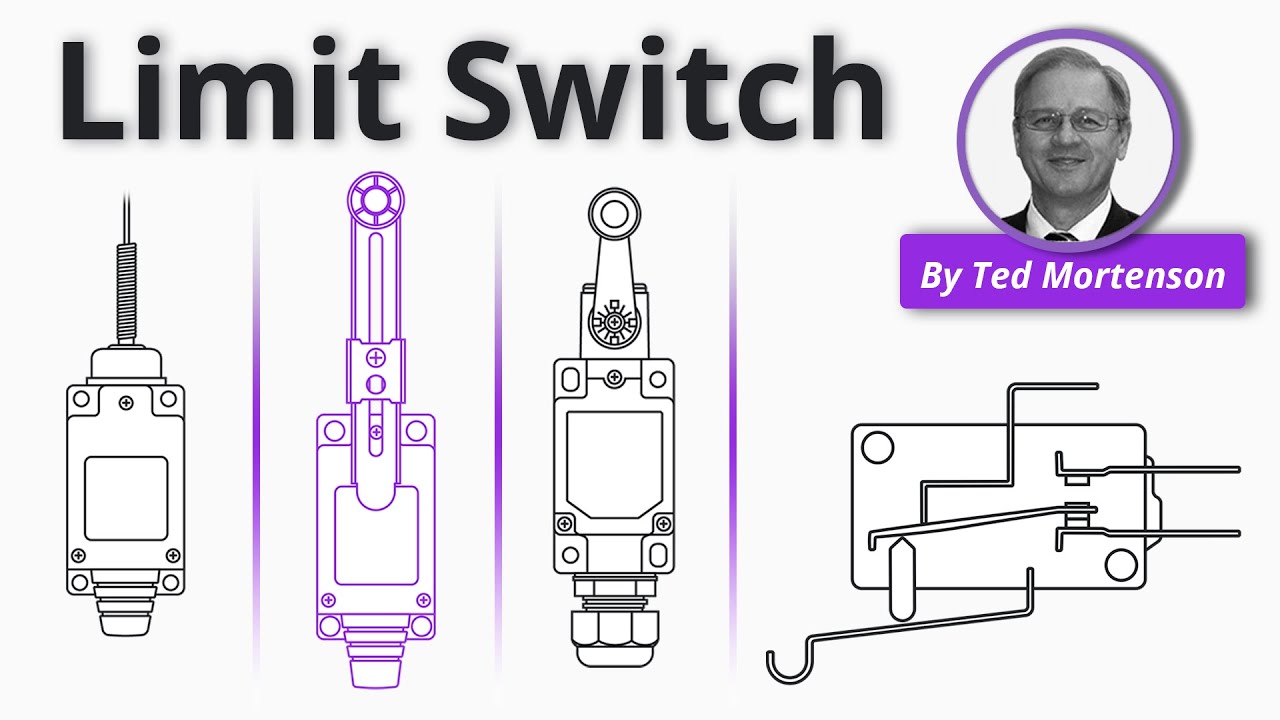
Watch the RealPars limit-switch working-principles video.
Häufig gestellte Fragen
What makes a limit switch heavy duty?
There is no single universal “heavy-duty” definition. Compare the exact actuator, enclosure protection, environmental tests, contact ratings, mechanical life and mounting limits against the machine requirements.
Does an IP66 marking mean the switch is suitable for every harsh environment?
No. An IP code covers specified enclosure ingress tests. Confirm chemical, oil, salt, temperature, UV, vibration and installed cable-entry requirements separately for the actual model and application.
Can a limit switch directly control a motor?
Do not assume so from a current value alone. Check the switch’s load category and the motor’s starting and inductive duty. A control relay or contactor may be required by the circuit design.
Can a general-purpose limit switch serve as a machine guard interlock?
Only when the machine’s risk assessment, applicable standards and validated safety-control design permit that exact component and architecture. A general position switch alone does not establish a safety function.