
Micro switch mounting screw torque must be set for the exact switch, supporting surface and fastener stack. Screw diameter alone cannot establish a safe setting. A housing can be secure yet distorted enough to change actuator behavior. Review the intended mounting features, load path and installed function before approving the assembly.
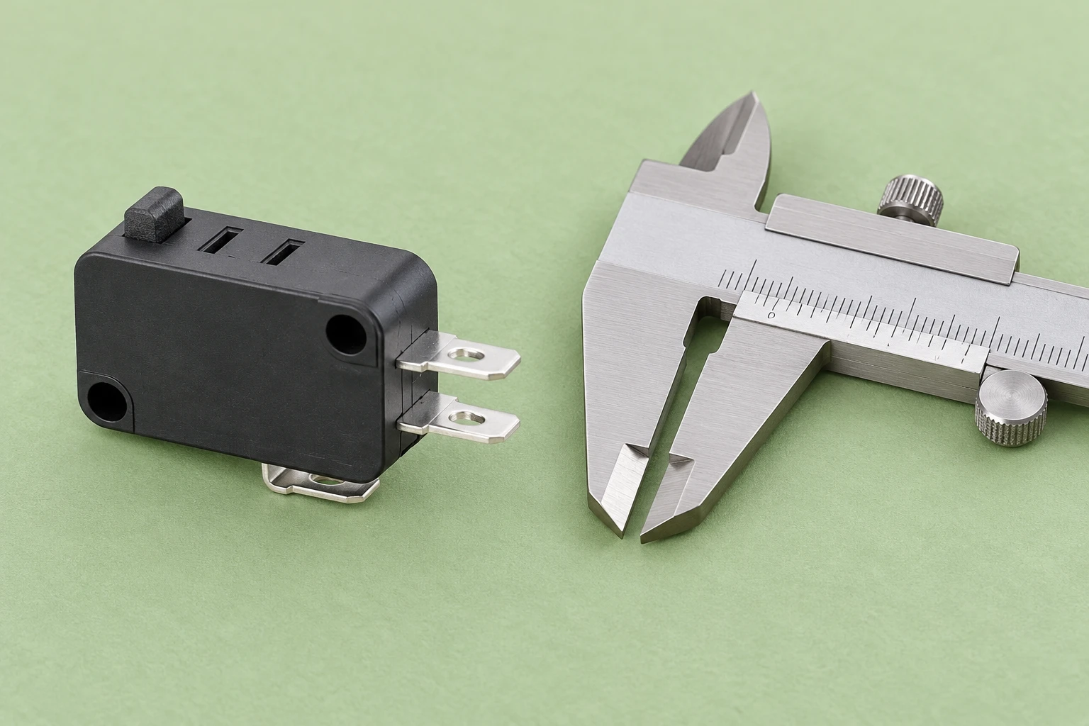
Das Mikroschalter der Serie KW7 is the LEMA product reference illustrated here. Its photograph identifies the external product, not an unlisted rating, accessory compatibility or test result. Obtain the current specification for the full order code before approving an assembly.
Why There Is No Universal Mounting Torque
A mounting torque cannot be selected from screw size alone. Applied torque is divided among thread friction, friction beneath the screw head or washer, and the work that creates clamp load. Changes in finish, lubrication, thread condition, or bearing surface can alter that distribution. Similar torque readings can therefore produce different loads on the switch housing.
The joint configuration matters just as much. A screw threaded into a metal bracket behaves differently from one forming threads in plastic. A through-bolt with a nut introduces another set of friction interfaces. A shoulder screw may control compression through its geometry, while an ordinary screw may continue compressing the housing as it advances.
Housing construction also changes the response. Wall thickness, mounting bosses, internal ribs, molding details, and material condition influence how the enclosure carries clamping force. A setting developed for one mounting arrangement should not be transferred to another merely because the switches look similar. Where supplier mounting instructions exist, use them as design inputs and verify their applicability to the actual assembly.
Define the Joint on the Assembly Drawing
The assembly drawing should describe the complete joint rather than leaving critical choices to the workstation. Identify the fastener, mating thread, washer or other bearing component, mounting orientation, and supporting surfaces. State whether the switch rests directly on a bracket, against a spacer, or within a locating feature. Make clear which features locate the switch and which provide retention.
Specify the intended contact conditions. A broad housing face may appear suitable for support while containing raised lettering, molding features, or a cover seam that prevents stable seating. Conversely, a mounting boss may be designed to carry load while adjacent housing surfaces should remain free. The drawing should prevent the assembler from treating every visible flat surface as a clamping surface.
Include clearance requirements where the fastener passes through the housing and where its end approaches other parts. A screw that bottoms in a blind hole can reach the programmed torque without securing the switch. An overly long screw can contact the enclosure, wiring, or mechanism. Neither condition is resolved by changing the torque setting.
Understand Material Behavior Under Sustained Clamping
Plastic housings can deform immediately during tightening and continue changing under sustained load. Temperature, moisture exposure, and time can influence stiffness and dimensional stability. A joint that feels firm during assembly may later lose retention, while a highly constrained housing may retain deformation that affects actuator movement.
Metal mounting surfaces need attention as well. Burrs, paint buildup, bent brackets, weld distortion, or debris can concentrate force beneath the housing. Tightening may pull the switch against those irregularities rather than create uniform support. Correct the interface instead of using additional torque to flatten the switch against it.
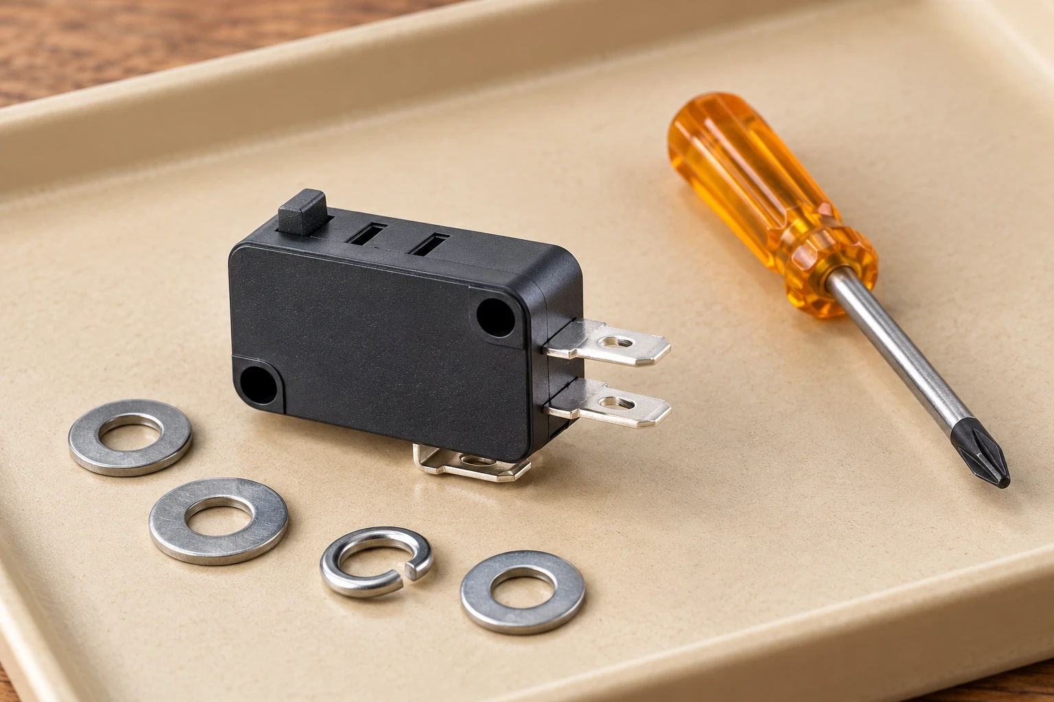
Washers and spacers should have a defined purpose. A washer can redistribute bearing pressure, but it may also bridge a recess, contact a cover edge, or interfere with a nearby actuator. A spacer can establish a stable load path, provided its ends seat correctly and its length suits the joint. Added hardware is not automatically protective.
Trace the Clamping Load Path
Follow the force from the screw head through every contacting component to the engaged thread. Ask where the load enters the housing, which features carry it, and where it leaves. The preferred path uses intended mounting features and stable support rather than unsupported walls, cover joints, terminals, or the actuator mechanism.
Consider the reaction to tightening torque as well as the axial clamp force. As the screw turns, friction beneath its head can drag the switch sideways or rotate it against a locator. If that motion is resisted by the actuator or electrical terminals, those features become unintended assembly tools. Locate and restrain the housing through appropriate structural surfaces.
Where the design requires compression control, consider a suitable shoulder, sleeve, or hard stop. Its function is to establish a predictable mechanical stack rather than depend entirely on operator judgment. However, the stop must not prevent retention or leave the housing loose. Validate the complete stack, including component variation and actual seating conditions.
| Joint condition | Likely concern | Practical assembly response |
|---|---|---|
| Housing rocks before tightening | Clamp load may bend the enclosure against uneven support | Inspect the seating surface and remove the cause of instability |
| Screw reaches torque without seating | Thread resistance or bottoming may imitate a completed joint | Check engagement, hole condition, and screw length |
| Switch moves during tightening | Final actuator position may depend on friction and operator restraint | Improve housing location and control the tightening sequence |
| Actuator response changes after mounting | Housing distortion or external interference may affect movement | Compare installed behavior with the unmounted baseline |
| Retention changes after environmental exposure | Material movement or joint relaxation may alter clamping | Reassess support, compression control, and retained function |
Design the Fixture Around Seating and Access
An assembly fixture should establish location without squeezing the housing into an artificial shape. Support the intended mounting surfaces and leave the actuator free unless a deliberate positioning step requires otherwise. Any fixture contact near a cover joint, terminal, or flexible wall should be reviewed for unintended loading.
Provide access that keeps the driver aligned with the screw. An angled driver can create side force, poor bit engagement, and inconsistent seating. The fixture should also prevent a loose switch from twisting as the screw first engages. Do not rely on the operator holding a small housing against driver reaction.
Check what happens when the assembly leaves the fixture. A rigid nest can temporarily conceal a distorted bracket or an unstable joint. Confirm that the switch retains its position and operates normally after fixture restraints are released. The final product, not the assembly fixture, must provide the required support.
Develop the Tightening Process Through Validation
Start with representative switches, fasteners, brackets, and production tooling. Include meaningful variation in the components and interfaces rather than testing only carefully selected parts. Document the starting condition, seating behavior, tightening method, and resulting function. Treat torque as a process variable whose suitability must be demonstrated, not as proof of a good joint by itself.
For mounting arrangements with multiple screws, evaluate how the tightening sequence affects seating. Bringing one screw fully down before the others can tilt or bend the housing. A controlled seating sequence may allow the switch to settle against its supports before final tightening. The chosen method should be repeatable without requiring the operator to judge housing flex by feel.
Observe the relationship between tool response and physical joint completion. Where suitable equipment is available, tightening traces can help distinguish seating from thread drag or an obstruction. They do not replace inspection or functional testing. A normal-looking tool result can still accompany a misplaced washer or a housing trapped on debris.
Validation should include retained position, housing condition, actuator operation, and electrical behavior after assembly and relevant conditioning. Select acceptance criteria from the product’s functional needs and applicable component information. Establish a controlled process only after the joint demonstrates both reliable retention and freedom from mounting-induced interference.
Preserve Actuator Clearance and Alignment
The actuator needs clearance throughout its intended movement, including return travel. Check nearby brackets, screw heads, washers, covers, and wiring. An interference that is absent in the rest position may appear during operation or as the surrounding mechanism moves. Inspect the actual motion path rather than relying only on a static gap.
Align the operating member so that it loads the actuator as intended. Side loading can change friction, bend a lever, or force a plunger against its guide. Mounting adjustment should not be used to compensate for an incompatible approach direction. If the mechanism requires lateral accommodation, address that in the operating interface.
Avoid using the switch as a mechanical stop unless the design explicitly provides for that duty. The surrounding mechanism should control its own travel without forcing excessive movement into the actuator. Also consider the return condition: the mechanism must release the actuator sufficiently for dependable reset rather than leave it partially loaded.
Validate the installed function and control changes
Compare the isolated contact state and actuator return before and after mounting, using the same defined motion and measurement method. Record the final position after the fixture releases the assembly. If operation changes, inspect seating, hardware and interference rather than choosing a different torque merely to make the symptom disappear. A contact check is evidence for that specific function, not proof of insulation, endurance or machine safety. Preserve the sample and mounting record when investigation is needed.
A production change to the bracket finish, washer, screw, housing variant or driver can change the joint. Identify the accepted configuration and decide what comparison is needed before release. The approved setting belongs to the validated assembly, with its installation instructions and acceptance criteria. Ask the supplier for the current mounting drawing and limitations for the complete code.
Technical references and the scope of this review
NASA Fastener Design Manual: NASA explains the influence of fastener and joint conditions on fastening behavior. Its general guidance does not assign a torque to a micro switch housing.
IEC 60068-2-21 termination and mounting robustness: The IEC catalogue identifies a test-method scope for terminations and integral mounting devices exposed to assembly or handling stress. Apply a relevant specification; the catalogue is not a product test report.
For the wider component decision, see Auswahl eines industriellen Mikroschalters für OEM-Schalttafeln. Complementary checks are covered in Mikroschalter: Vorweg, Nachweg und Differenzweg erklärt und Mikroschalter-Betätigungskraft: Wie man Kraft und Weg aufeinander abstimmt. These pages address separate questions and do not replace the acceptance evidence defined here.
Further learning
This independent lesson explains stress and strain, providing physical background for mechanical loading. It does not assign a test force or fastening setting to the illustrated switch.
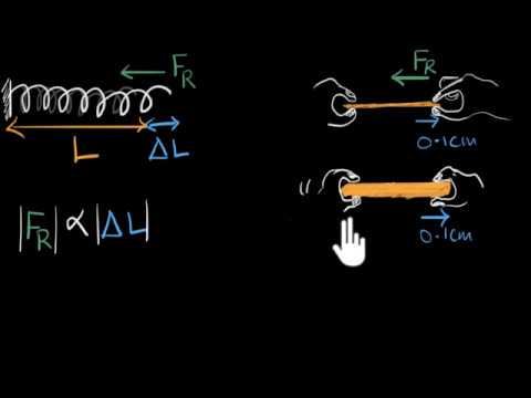
Watch Stress & strain | Class 11 (India) | Physics | Khan Academy — Khan Academy India – English
Häufig gestellte Fragen
Can screw size alone determine mounting torque?
No. The component, support, fastener stack and installation method must be considered together using the applicable instructions and validation.
Can I increase torque to stop the housing moving?
Resolve the seating and retention design first. Extra torque can distort a housing or conceal a joint problem.
Should the actuator be used to locate the switch during tightening?
Use the approved structural locating features. Loading the actuator can create an unintended assembly force.
What should be checked after mounting?
Check the specified position, actuator movement, return and electrical behavior, with a documented baseline and acceptance method.