
A foot switch for a pump should normally be selected as part of the pump’s control system: define the required pedal action, identify the receiving input or switching device, and verify the complete electrical duty before connecting a load. A momentary pedal can request pumping while held; a maintained pedal can request a continuing state. Neither action automatically provides safe stopping, accurate dosing or protection against unexpected restart. This guide gives equipment builders a practical specification and validation checklist for electrical foot controls used around pumping operations.
It concerns an electrical command device, not a pedal-operated mechanical pump or a pneumatic valve. An ordinary industrial pedal must not be assumed suitable for medical treatment, hazardous fluids or a safety function without the applicable system assessment.
Describe the pumping task before choosing the pedal
Start with the operator’s task. Does the operator need both hands to position a container, hold a hose or align a fixture? Is the command intended to run the pump continuously, request a timed cycle or permit a process only while the pedal is held? These are different control functions. The same physical pedal can produce very different machine behavior depending on the receiving circuit.
Record the fluid, pump type, location and consequences of an unintended command. Include the pressure and motion hazards, splash exposure, nearby moving equipment and the operator’s working position. A hands-free command can be convenient while introducing a new risk of accidental operation. Decide how the overall machine prevents that event before specifying a pedal’s color or enclosure material.
El industrial foot switch selection guide provides the broader component-selection framework. The pump-specific questions below should become part of the equipment specification and acceptance record.
Choose momentary or maintained action deliberately
A momentary pedal returns to its resting state when released. It can be used to request a hold-to-run command when the control design requires that behavior. However, pump motion or fluid flow may continue briefly after the request ends, depending on the pump and process. Test the actual stopping behavior; do not equate a released electrical contact with zero flow or zero pressure.
A maintained action retains a selected contact state until the next specified operation. It can suit a deliberate start-and-stop request, but the controller must interpret that request correctly. Consider what should happen when power returns while the pedal remains in its operated state. The correct restart behavior belongs in the machine requirements, not in a guess about how an ordinary switch will behave.
For batch dispensing, a pedal may request one cycle rather than directly determine its length. The controller should manage the approved sequence. Do not promise dose accuracy from a contact switch alone. Flow, timing and delivered quantity require process-specific verification. Review momentary and maintained pedal actions before finalizing the command sequence.
Separate the command circuit from pump power
Identify whether the pedal feeds a controller input, a relay or contactor coil, or a load directly. The rating requirements differ. A current marking for one duty does not automatically authorize switching a pump motor, and an AC rating cannot simply be carried over to a DC load. Verify the exact voltage, load type, operating frequency and switching conditions against the selected model documentation.
A relay or motor-control interface can separate a low-power command from the load circuit. It still needs appropriate ratings, protective arrangements and system design. A relay by itself does not make an installation safe. The pump’s starter, drive or controller may also require a specific input signal or operating mode.
El foot switch contact duty guide helps distinguish the specification questions. Ask for evidence applicable to the exact order code and intended duty rather than relying on a broad family description or a larger current number.
Use a relay-system lesson to understand the interface
The RealPars educational video explains the separation between a switching command and a relay-controlled load. That concept is useful when deciding how a pedal should communicate with a pump controller. The example is background instruction, not a wiring prescription for a particular pump or approval of a specific LEMA model.
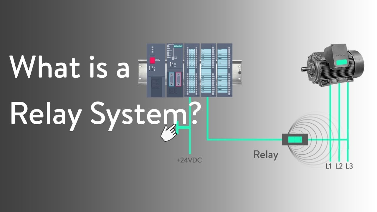
RealPars relay-system teaching source · Watch the lesson on YouTube.
Match the physical pedal to the workstation
Evaluate the pedal where the operator will actually use it. The base should remain stable through normal pressing and release. The operator should be able to reach it without an awkward stance or interference from a container, hose or machine frame. Check representative footwear, especially where work boots or protective overshoes change access.
A guard can reduce certain accidental contacts with the pedal, but its geometry must still permit intended operation. It is not proof that the assembled machine has a safety-rated control. Check the access space, the consequences of a dropped object and whether the pedal can be trapped in an operated position. Avoid mounting arrangements that restrict travel or prevent return.
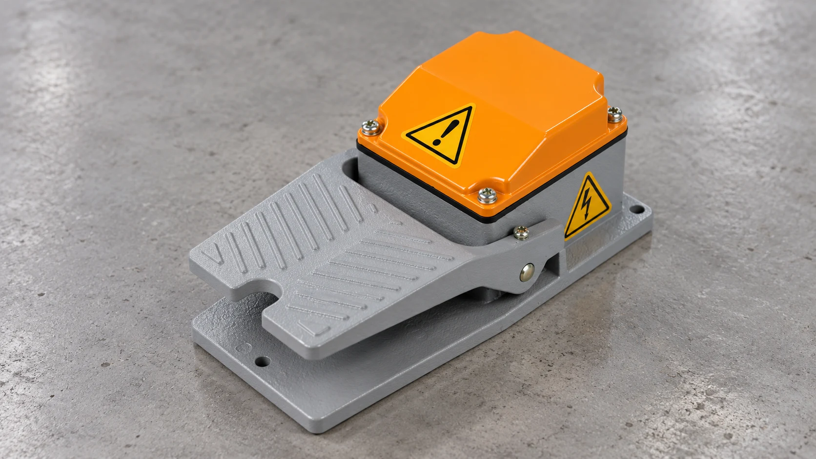
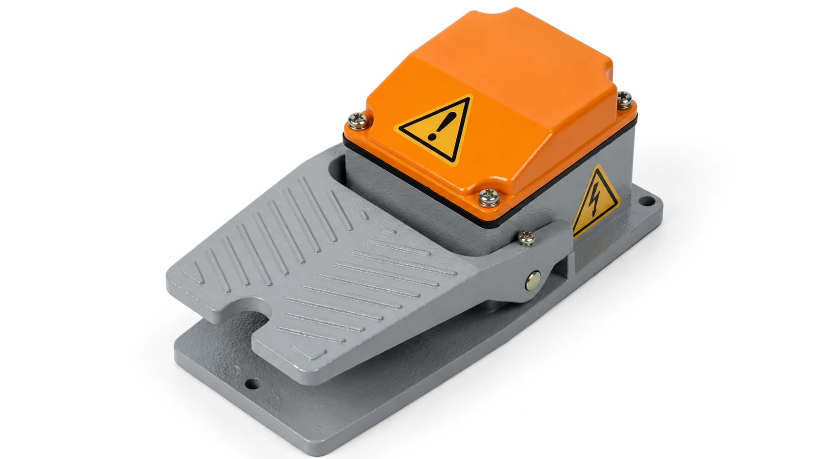
El LEMA LF family provides real pedal configurations for evaluation. The guarded example illustrated here shows external form only. Pump compatibility, circuit ratings, enclosure performance and action must be confirmed for the chosen order code.
Check fluid exposure and cable routing separately
Describe what can reach the pedal: occasional drips, washdown spray, cleaning chemicals, dust, condensation or an outdoor environment. Ask for the protection information applicable to the full assembly, including its cable entry and connector. Do not infer chemical resistance, washdown suitability or outdoor service from a metal housing or the word “industrial.”
Position the pedal to avoid unnecessary splash and trip hazards while preserving the operator’s control of the task. Route the cable so moving machinery, cart wheels and hose handling cannot crush or pull it. Check the available bend space near the pedal and connector. A robust enclosure cannot protect a cable that is repeatedly pinched by the workstation.
If a connector is required, specify the mating part, pin assignments, retention method and relevant exposure conditions. Preserve the distinction between a contact pair and any additional circuits. The foot switch connector guide can support the harness discussion without assuming that visually similar plugs are interchangeable.
Build a specification that the supplier can verify
| Specification item | Information to provide | Evidencia a solicitar | Validation at the machine |
|---|---|---|---|
| Pedal action | Momentary, maintained or cycle-request sequence | Exact action and contact diagram | Pressed, released and repeated-command behavior |
| Interfaz eléctrica | Controller input, coil or direct load and actual duty | Model-specific ratings and connection requirements | Signal compatibility and response under the intended operating conditions |
| Physical installation | Mounting location, access and footwear | Dimension drawing and fastening guidance | Stability, complete travel and intended operator access |
| Medio ambiente | Fluid, cleaning method, dust and temperature conditions | Applicable enclosure and material information | Installed cable-entry and connector protection |
| Restart behavior | Required response after interruption or mode change | Control-system design requirements | No unintended pumping during the specified recovery sequence |
| Mantenimiento | Inspection access and approved replacement requirements | Service instructions and traceable order code | Repeatable inspection and return-to-service process |
This is a qualitative procurement checklist. It contains no invented load limits or enclosure claims. Populate it with the documentation for the actual pedal and pump system.
Validate the complete pumping sequence
Commission the assembly through a controlled test plan. Check the intended command from the operator’s position, the response of the receiving circuit and the resulting pump behavior. Include release, repeated pressing and the specified operating-mode transitions. Define acceptance criteria before testing so the result is more precise than “the pump ran.”
Where the risk assessment requires them, verify the independent protective functions and recovery behavior. Consider interruption of power, disconnected control wiring and a command that remains present. These are machine-design questions; they cannot be resolved solely by changing the pedal to a different mechanical action.
During servicing, a released pedal is not an energy isolator. OSHA’s hazardous-energy guidance explains the need to control unexpected startup and stored energy. The installation’s procedure must address pressure and other relevant energy as well as electrical power.
Prepare maintenance and replacement information
Keep the order code, drawing, harness pinout, control sequence and acceptance results with the equipment record. Inspect for damaged tread, enclosure movement, obstruction, cable wear and connection damage at an interval justified by the use conditions. A generic calendar interval cannot account for every pumping workstation.
When a pedal fails, record the symptom and operating conditions before choosing a replacement. A similar housing can conceal a different contact action or connection. Preserve the approved function and revalidate the affected machine behavior after repair. Do not bypass the control or a protective function to continue a pumping operation.
For an inquiry to LEMA, send the completed checklist, installation photographs and the actual electrical interface requirements. This makes it possible to evaluate a candidate component without guessing at pump compatibility or claiming a certification that has not been established.
Preguntas frecuentes
Can any foot switch directly power a pump?
No. Confirm the exact load duty and switch rating. Many applications use the pedal as a command to a controller or properly selected switching interface.
Does a momentary pedal guarantee immediate flow stopping?
No. It changes a command state. Actual flow and pressure response depend on the pump, process and control system.
Is a guarded pedal automatically a safety device?
No. A physical guard is not evidence that the complete pedal or machine meets a safety-function requirement.
What should I send when requesting a pump-control pedal?
Send the desired action, contact function, interface duty, environment, mounting constraints, connector information and required restart behavior.